
- inCAD Library Home
- > No.000016 Continuity inspection fixture
No.000016 Continuity inspection fixture
12
12
Spring held surface inspection fixture
Related Category


T Shaped Handle
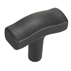
| Product name | T-Shaped Handles |
|---|---|
| Part number | TSPF50-3 |
| Features | T-shaped resin handle |
* Orange colored cells in the table below indicate the part numbers used in this example.
Selection criteria
Suitable for work operations.
Available sizes
■T-Shaped Handles
| Material / Surface treatment | |
|---|---|
| Handle | Threads |
| Glass fiber reinforced nylon | EN 1.0038 Equiv. (Inserts) / Trivalent chromate |
| (Matte black) | |
■Sizes and Dimensions
| Thread type | Overall width | Mounting thread DIA. (Coarse) | Thread length | Mounting height | |||
|---|---|---|---|---|---|---|---|
| 10 | 15 | 20 | 25 | ||||
| Male threads | 50 | M4 | ○ | ○ | ○ | - | 43 |
| M5 | ○ | ○ | ○ | - | |||
| M6 | ○ | ○ | ○ | - | |||
| 80 | M6 | - | ○ | ○ | ○ | ||
| M8 | - | ○ | ○ | ○ | |||
| M10 | - | ○ | ○ | ○ | |||
| Female threads | 50 | M3 ・ M4 ・ M5 | 20 | ||||
| 80 | M5 ・ M6 ・ M8 | 25 | |||||

Extension Spring
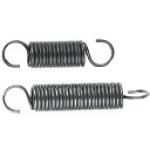
| Product name | Extra Light Load/Light Load/Light to Medium Load/Medium Load |
|---|---|
| Part number | AUY8-50 |
* Orange colored cells in the table below indicate the part numbers used in this example.
Selection criteria
Simplest means of position return function.
Available sizes
■Extension Springs - Standard Lengths
| Load type | Material | O.D. range | Free length range | Hook on both ends | ||
|---|---|---|---|---|---|---|
| Spring Steel (ASTM A228) | EN 1.4301 Equiv. | S shaped | 90 deg. S shaped | |||
| Extra light load | ○ | ○ | Ø2 - 12 | 10 - 100 | ○ | - |
| Light load | ○ | △ | Ø2 - 20 | 10 - 175 | ○ | △ |
| Light Med. load | ○ | △ | Ø2 - 20 | 10 - 175 | ○ | △ |
| Med. load | ○ | △ | Ø2 - 24 | 10 - 200 | ○ | △ |
| Med.Heavy load | ○ | - | Ø2 - 12 | 10 - 100 | ○ | - |
| Heavy load | ○ | △ | Ø3 - 24 | 10 - 200 | ○ | △ |
Performance info.
■Load info. of extension spring
| Load type | Reference load (N) | |
|---|---|---|
| Min. | Max. | |
| Extra light load | 0.69 | 19.6 |
| Light load | 1.86 | 78.45 |
| Light Med. load | 2.45 | 98.07 |
| Med. load | 3.53 | 225.55 |
| Med.Heavy load | 6.47 | 83.36 |
| Heavy load | 8.8 | 430.51 |
Technical calculations
■Load calculations of extension spring
P = Pi + (k x F)
- P: Load (N)
- Pi: Initial tension (N)
- k: Spring constant (N/mm)
- F: Deflection (mm)

Contact Probe

| Product name | Contact Probes/NP90SF/NP90 Series |
|---|---|
| Part number | NP90HD-C |
* Orange colored cells in the table below indicate the part numbers used in this example.
Selection criteria
Essential for fixture function
Available sizes
■Contact Probes - NP90SF, NP90 Series
| Part name | Material | Surface treatment |
|---|---|---|
| Plunger | EN CW101C Equiv. | Nickel base rhodium plated |
| Barrel | Brass | Nickel base gold plated |
| Spring | Carbon Steel | Gold plated |
| Ball | JIS-SUJ (Bearing Steel) | Gold plated |
■Tip shape

| Tip shape | Min. mounting pitch | Full stroke | Initial spring pressure | |
|---|---|---|---|---|
| A | 4.5 | 6.4 | 10gf, 40gf, 146gf | |
| B | 3.5 | |||
| C | ||||
| D | 4.5 | |||
| E | 3.5 | |||
| G | ||||
| AS | ||||
Performance info.
■Contact probe (Min. mounting pitch 3.5mm) load info.
| Spring pressure | Allowable current | Resistance | Replacement frequency guideline | |
|---|---|---|---|---|
| Initial | 2/3 stroke | |||
| 10gf | 50gf | 1.5A | 80mΩ | 300,000 cycles |
| 40gf | 150gf | |||
| 146gf | 250gf | |||


-
 TERMS AND CONDITIONS FOR USE OF CAD DATA
-
Your access to the CAD data that MISUMI Corporation (hereinafter referred to as the Company) posts on this site (including 3D CAD data, intermediate 3D CAD data and 2D CAD data; hereinafter referred to as the Data) are of products manufactured and/or sold by the Company (hereinafter referred to as the Products) assumes that you have read and accepted these terms and conditions which govern your use of the Data. If you do not agree to these terms and conditions, you must stop using this website and the Data. You must not use the Data for any unlawful purpose or in any manner inconsistent with these terms and conditions.
- 1. CAD Data
- The Data is prepared for assisting the Company's users in the CAD design process by providing dimensions and other Product information. In order to provide the best speed and stability working within this site, the Product drawings were simplified to reduce the size of the Data. For instance, some of the Products are shown without the oil groove shape, screws or spring shape. Also, please be aware that the tolerance, surface roughness and/or chamfer of the Data may vary from the actual Products.
- 2. Disclaimer on Data
- While the Company has carefully prepared the Data, accuracy of the Data is not guaranteed and is subject to the variances as described above. The Company may also modify, add or delete the Data at any time without prior notice. The Company assumes no liability for any direct, indirect, consequential or special damages that you may claim resulted from your use of the Data or any changes to or deletions of the Data regardless of the reason. The Company provides no warranty as to the quality, accuracy, functionality, safety or reliability of the combination of Products and parts. Example applications and combinations of the Products are provided for illustrative purposes only.
- 3. Copyright
-
Copyrights to the content and the Data belong to the Company or the manufacturers of the Products. The said copyright is protected by the Copyright Act and international treaties. The use (including duplication, modification, uploading, posting, transmission, distribution, licensing, sales and publishing) of the Data except for the purpose to use the Data described above without prior approval of the Company is not allowed. The Data cannot be used for any purposes (including sales promotion) except for designing your machine. If you violate this provision or the laws or regulations, the Company may prohibit you from the use of the Data, the Company’s site and/or take legal action. So long as you comply with these terms and conditions, the Company grants to you a non-exclusive, non-transferable, revocable license to access and use the Data for the sole purpose of assisting you in designing machines that incorporate products.
- 4. Disclaimer of Warranty
- ANY AND ALL CONTENT APPEARING ON THIS WEB SITE IS PROVIDED FOR INFORMATIONAL PURPOSES ONLY. THIS WEB SITE, ITS CONTENT AND ITS LINKS ARE PROVIDED ON AN "AS IS" AND "AS AVAILABLE" BASIS AND ARE USED ONLY AT YOUR SOLE RISK, TO THE FULLEST EXTENT PERMISSIBLE BY LAW. THE COMPANY DISCLAIMS ALL WARRANTIES, EXPRESS OR IMPLIED, OF ANY KIND, REGARDING THIS WEB SITE (INCLUDING ITS CONTENT, HARDWARE, SOFTWARE AND LINKS), INCLUDING AS TO FITNESS FOR A PARTICULAR PURPOSE, MERCHANTABILITY, TITLE, NON INFRINGEMENT, RESULTS, ACCURACY, COMPLETENESS, ACCESSIBILITY, COMPATIBILITY, SECURITY AND FREEDOM FROM COMPUTER VIRUS. THE COMPANY WILL NOT BE LIABLE FOR ANY DAMAGES OR LOSSES, INCLUDING DIRECT, INDIRECT, CONSEQUENTIAL, SPECIAL, INCIDENTAL OR PUNITIVE DAMAGES AND/OR LOST PROFITS, IN CONNECTION WITH USE OF THE INTERNET, THIS WEB SITE, ITS CONTENT OR ITS LINKS
Further, the Company will not be liable to you for any failure or delay by the Company to provide access to the Data or any of its obligations under these terms and conditions where such failure or delay is the direct or indirect result of any circumstances beyond the Company's reasonable control (and the Company's obligations will be suspended for the duration of such circumstances). - 5. Policy of Third Parties
- You may be required to separately agree to third party's policies if you use third party software to create or browse the Data or use a third party’s CAD data. In this case, the Company does not assume any responsibility for defects of such CAD data or the software of the third party or violation of their rights. Understand them before use.
CAD Data Download (Unit Assembly)
CAD Data Download: File Format
Cautions on the CAD data
-
Assembly data shows the assembly drawings in the concept design phase. The sole purpose of the data is to explain the structure and functionality of the assembly and is not considered nor to be used as a final design.
You will need to edit the Data so that it meets your specific design conditions. -
The CAD data unit assembly consists of sub-assemblies.
Each sub-assembly unit can be used as it is or can be edited. - The Data for fabricated parts is based on easy-to-edit dimensions and shapes in sketches and histories.
- The Data including the third-part components are made by the Company.
* The part in the frame is a sub-assembly unit.
-
Your access to the CAD data that MISUMI Corporation (hereinafter referred to as the Company) posts on this site (including 3D CAD data, intermediate 3D CAD data and 2D CAD data; hereinafter referred to as the Data) are of products manufactured and/or sold by the Company (hereinafter referred to as the Products) assumes that you have read and accepted these terms and conditions which govern your use of the Data. If you do not agree to these terms and conditions, you must stop using this website and the Data. You must not use the Data for any unlawful purpose or in any manner inconsistent with these terms and conditions.
-

- * Unit assembly CAD data consists of some sub-assemblies.
Each sub-assembly unit can be used as it is or can be edited.
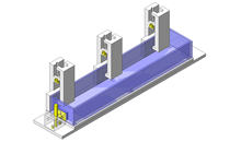
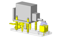
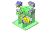
Application Overview
Purpose
- A device used to inspect surface continuity using a contact probe.
Points for use
- Manually held by toggle clamp operations.
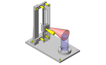
- Contact probe is lowered manually.
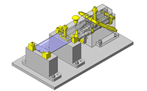
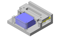
Target workpiece
- Molded plastic products
Dims.: W122 x D60 x H20
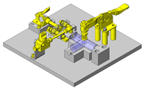
Design Specifications
Operating Conditions or Design Requirements
- The toggle clamp operation angle is 90°.
- External dims.: W230 x D100 x H219
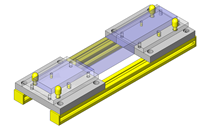
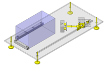
Selection Criteria for Main Components
- Toggle clamp
- Maintained type with a horizontal handle is mounted on a 90° incline to save space.
- Extension spring
- Spring with a low constant force is selected to ease the operation effort.
- Linear guide
- Since the moment load is small, select a guide comparable to the fixture size.
Design Evaluation
Verification of main components
- Spring constant extension force is low to make operation easier.
- Extension spring load
- Formula: Reaction force kx + Initial tension
- Assumed operation load: F = 10.335N
- Initial tension: 2.35N
- Assumed deflection during operation: x = 39.5mm (When set 0mm, when stroked 39.5mm)
- Moving part weight: 1.1N
- k = (F - Initial tension + moving part weight) / x = (10.335 - 2.35 + 1.1) / 39.5 = 0.23
- Spring constant: k = 0.23N/mm is selected.
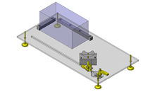
Other Design Consideration
- Linear guide stabilizes linear motion.
- Select an extension spring with a constant large enough that the probe does not fall down by its own weight.
Explore Similar Application Examples
Page
-
/
-


Payment Method


On-Demand Manufacturing
Certificates


Copyright © MISUMI Corporation All Rights Reserved.