
- inCAD Library Home
- > No.000160 Cylinder stroke with rack and gear mechanism
No.000160 Cylinder stroke with rack and gear mechanism
44
44
Stroke speed is increased by adding gear and rack to cylinder push.
Related Category


Height Adjusting Blocks for Miniature Linear Guides
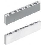
| Product name | Height Adjusting Blocks for Miniature Linear Guides |
|---|---|
| Part number | GETE13-145-49 |
| Features | Miniature Slide Guides Standard Rail Type-Compatible Height Adjusting Block |
* Orange colored cells in the table below indicate the part numbers used in this example.
Selection criteria
Has screw holes for mounting the linear guide
Available sizes
■Height Adjusting Blocks for Miniature Linear Guides (Selectable sizes)
| Type | Material | Surface Treatment | |
|---|---|---|---|
| Datum Side | Free Side | EN 1.1191 Equiv. | Electroless Nickel Plating |
| EN AW-5052 Equiv. | Clear Anodize | ||
■Sizes and Dimensions
| Type | Slide Guide Height | Overall Length | Height (1 mm Increments) |
|---|---|---|---|
| Datum Side Free Side | 8 | 40 | 10-60 |
| 55 | |||
| 70 | |||
| 85 | |||
| 100 | |||
| 115 | |||
| 130 | |||
| 10 | 55 | ||
| 75 | |||
| 95 | |||
| 115 | |||
| 135 | |||
| 155 | |||
| 175 | |||
| 195 | |||
| 215 | |||
| 235 | |||
| 255 | |||
| 275 | |||
| 13 | 70 | ||
| 95 | |||
| 120 | |||
| 145 | |||
| 170 | |||
| 195 | |||
| 220 | |||
| 245 | |||
| 270 | |||
| 295 | |||
| 320 | |||
| 345 | |||
| 370 | |||
| 395 | |||
| 16 | 110 | ||
| 150 | |||
| 190 | |||
| 230 | |||
| 270 | |||
| 310 | |||
| 350 | |||
| 390 | |||
| 430 | |||
| 470 | |||
| 20 | 160 | ||
| 220 | |||
| 280 | |||
| 340 | |||
| 400 | |||
| 460 |

Gear Racks
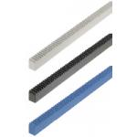
| Product name | Gear Racks/Pressure Angle 20Deg./Configurable L Dimension |
|---|---|
| Part number | RGEAL1.0HT-60-A10-B40 |
| Features | Gear Racks - Pressure Angle 20Deg., Configurable L Dimension |
* Orange colored cells in the table below indicate the part numbers used in this example.
Selection criteria
Economical
Available sizes
■Rack Gear, Configurable Length Type (One End Machined)
| Material | Surface Treatment |
|---|---|
| EN 1.1191 Equiv. | Black Oxide |
| Free-Cutting Brass Bar | - |
| EN 1.4301 Equiv. | - |
| MC Nylon | - |
| Material | Module | Tooth Width | Overall Length 1 mm Increments |
|---|---|---|---|
| EN 1.1191 Equiv. | 1.0 | 10 | 20-400 |
| 1.5 | 15 | ||
| 2.0 | 20 | ||
| 2.5 | 25 | ||
| 3.0 | 30 | ||
| Free-Cutting Brass Bar | 0.5 | 3 | 20-280 |
| 0.8 | 4 | ||
| EN 1.4301 Equiv. | 0.5 | 3 | 20-280 |
| 0.8 | 4 | ||
| 1.0 | 10 | 20-480 | |
| 1.5 | 15 | ||
| 2.0 | 20 | ||
| 2.5 | 25 | ||
| 3.0 | 30 | ||
| MC Nylon | 0.5 | 3 | 20-280 |
| 0.8 | 4 | ||
| 1.0 | 10 | 20-480 |
Accuracy Info
■Rack Gear (Accuracy Information)
Accuracy: Accumulated Pitch Error (µm)
| Module | Overall Length | ||||
|---|---|---|---|---|---|
| 100 or less | 101-300 | 301-500 | 501-1000 | 1001-1980 | |
| 0.5-1.5 | 54 (76) | 65 (92) | 72 (101) | 100 (117) | 99 (139) |
| 2.0-3.0 | 62 (86) | 73 (102) | 80 (112) | 91 (128) | 105 (148) |

Spur Gears
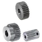
| Product name | Spur Gears/Pressure Angle 20Deg./Module 1.0 |
|---|---|
| Part number | GEAKS1.0-45-10-A-10N |
* Orange colored cells in the table below indicate the part numbers used in this example.
Selection criteria
Economical
Available sizes
■Spur Gears (Ground)
| Material | Surface Treatment | Accessory |
|---|---|---|
| EN 1.1191 Equiv. | - | Set Screw (EN 1.7220 Equiv. Black Oxide) |
| Black Oxide | ||
| Electroless Nickel Plating | ||
| EN 1.4301 Equiv. | - | Set Screw (EN 1.4301 Equiv. ) |
■Sizes and Dimensions
| Type | Gear Shape | Module | Number of Teeth | Tooth Width | Shaft Bore DIA.(1 mm increment) | |
|---|---|---|---|---|---|---|
| Round Hole Round Hole + Tap | Keyway Keyway + Tap | |||||
| Standard | Cylinder | 1.0 | 12 | 10 12 | 6-8 | - |
| 13 | 6-10 | |||||
| Cylinder No disc hub | 14 | |||||
| 15 | ||||||
| 16 | 6-12 | |||||
| 17 | ||||||
| 18 | ||||||
| No disc hub With Disc Hub | 19 | 6-10 | 8N | |||
| 20 | 6-10 | |||||
| 21 | 6-12 | 8N ・ 10N | ||||
| 22 | ||||||
| 23 | ||||||
| 24 | ||||||
| 25 | ||||||
| 26 | 6-15 | 8N-12N | ||||
| 27 | ||||||
| 28 | 8-17 | 10N-12N | ||||
| 29 | 6-17 | 8N-15N | ||||
| 30 | 8-17 | 10N-15N | ||||
| 32 | 10 | 8-18 | ||||
| 34 | ||||||
| 35 | 8-20 | 10N-17N | ||||
| 36 | ||||||
| 38 | ||||||
| 40 | ||||||
| 42 | ||||||
| 44 | ||||||
| 45 | ||||||
| 46 | ||||||
| 48 | 8-30 | 10N-27N | ||||
| 50 | 8-32 | 10N-38N | ||||
| 52 | ||||||
| 54 | ||||||
| 55 | ||||||
| 56 | ||||||
| 58 | ||||||
| 60 | 10-35 | 12N-31N | ||||
| 62 | ||||||
| 64 | ||||||
| 65 | ||||||
| 66 | ||||||
| 68 | ||||||
| 70 | 10-39 | 12N-35N | ||||
| 72 | ||||||
| 75 | ||||||
| 80 | 10-42 | 12N-38N | ||||
| 84 | 15N-38N | |||||
| 85 | ||||||
| 90 | ||||||
| 95 | ||||||
| 96 | ||||||
| 100 | 17-42 | 17N-38N | ||||
| 110 | 17-49 | 17N-45N | ||||
| 120 | ||||||
| Gear specifications | Shaft Bore Specs. | |||
|---|---|---|---|---|
| Straight Bore | Straight Bore +Tap | Keyway | Keyway +Tap | |
| No hub | ○ | ○ | ||
| With Hub | ○ | ○ | ○ | |
Accuracy Info
■Accuracy of Spur Gear
Gear accuracy: Previous JIS B 1702 4 Class (New JIS B 1702-1 - 8 class equivalent)
Shaft Bore Dia. Tolerance: H7


-

-
 TERMS AND CONDITIONS FOR USE OF CAD DATA
-
Your access to the CAD data that MISUMI Corporation (hereinafter referred to as the Company) posts on this site (including 3D CAD data, intermediate 3D CAD data and 2D CAD data; hereinafter referred to as the Data) are of products manufactured and/or sold by the Company (hereinafter referred to as the Products) assumes that you have read and accepted these terms and conditions which govern your use of the Data. If you do not agree to these terms and conditions, you must stop using this website and the Data. You must not use the Data for any unlawful purpose or in any manner inconsistent with these terms and conditions.
- 1. CAD Data
- The Data is prepared for assisting the Company's users in the CAD design process by providing dimensions and other Product information. In order to provide the best speed and stability working within this site, the Product drawings were simplified to reduce the size of the Data. For instance, some of the Products are shown without the oil groove shape, screws or spring shape. Also, please be aware that the tolerance, surface roughness and/or chamfer of the Data may vary from the actual Products.
- 2. Disclaimer on Data
- While the Company has carefully prepared the Data, accuracy of the Data is not guaranteed and is subject to the variances as described above. The Company may also modify, add or delete the Data at any time without prior notice. The Company assumes no liability for any direct, indirect, consequential or special damages that you may claim resulted from your use of the Data or any changes to or deletions of the Data regardless of the reason. The Company provides no warranty as to the quality, accuracy, functionality, safety or reliability of the combination of Products and parts. Example applications and combinations of the Products are provided for illustrative purposes only.
- 3. Copyright
-
Copyrights to the content and the Data belong to the Company or the manufacturers of the Products. The said copyright is protected by the Copyright Act and international treaties. The use (including duplication, modification, uploading, posting, transmission, distribution, licensing, sales and publishing) of the Data except for the purpose to use the Data described above without prior approval of the Company is not allowed. The Data cannot be used for any purposes (including sales promotion) except for designing your machine. If you violate this provision or the laws or regulations, the Company may prohibit you from the use of the Data, the Company’s site and/or take legal action. So long as you comply with these terms and conditions, the Company grants to you a non-exclusive, non-transferable, revocable license to access and use the Data for the sole purpose of assisting you in designing machines that incorporate products.
- 4. Disclaimer of Warranty
- ANY AND ALL CONTENT APPEARING ON THIS WEB SITE IS PROVIDED FOR INFORMATIONAL PURPOSES ONLY. THIS WEB SITE, ITS CONTENT AND ITS LINKS ARE PROVIDED ON AN "AS IS" AND "AS AVAILABLE" BASIS AND ARE USED ONLY AT YOUR SOLE RISK, TO THE FULLEST EXTENT PERMISSIBLE BY LAW. THE COMPANY DISCLAIMS ALL WARRANTIES, EXPRESS OR IMPLIED, OF ANY KIND, REGARDING THIS WEB SITE (INCLUDING ITS CONTENT, HARDWARE, SOFTWARE AND LINKS), INCLUDING AS TO FITNESS FOR A PARTICULAR PURPOSE, MERCHANTABILITY, TITLE, NON INFRINGEMENT, RESULTS, ACCURACY, COMPLETENESS, ACCESSIBILITY, COMPATIBILITY, SECURITY AND FREEDOM FROM COMPUTER VIRUS. THE COMPANY WILL NOT BE LIABLE FOR ANY DAMAGES OR LOSSES, INCLUDING DIRECT, INDIRECT, CONSEQUENTIAL, SPECIAL, INCIDENTAL OR PUNITIVE DAMAGES AND/OR LOST PROFITS, IN CONNECTION WITH USE OF THE INTERNET, THIS WEB SITE, ITS CONTENT OR ITS LINKS
Further, the Company will not be liable to you for any failure or delay by the Company to provide access to the Data or any of its obligations under these terms and conditions where such failure or delay is the direct or indirect result of any circumstances beyond the Company's reasonable control (and the Company's obligations will be suspended for the duration of such circumstances). - 5. Policy of Third Parties
- You may be required to separately agree to third party's policies if you use third party software to create or browse the Data or use a third party’s CAD data. In this case, the Company does not assume any responsibility for defects of such CAD data or the software of the third party or violation of their rights. Understand them before use.
CAD Data Download (Unit Assembly)
CAD Data Download: File Format
Cautions on the CAD data
-
Assembly data shows the assembly drawings in the concept design phase. The sole purpose of the data is to explain the structure and functionality of the assembly and is not considered nor to be used as a final design.
You will need to edit the Data so that it meets your specific design conditions. -
The CAD data unit assembly consists of sub-assemblies.
Each sub-assembly unit can be used as it is or can be edited. - The Data for fabricated parts is based on easy-to-edit dimensions and shapes in sketches and histories.
- The Data including the third-part components are made by the Company.
* The part in the frame is a sub-assembly unit.
-
Your access to the CAD data that MISUMI Corporation (hereinafter referred to as the Company) posts on this site (including 3D CAD data, intermediate 3D CAD data and 2D CAD data; hereinafter referred to as the Data) are of products manufactured and/or sold by the Company (hereinafter referred to as the Products) assumes that you have read and accepted these terms and conditions which govern your use of the Data. If you do not agree to these terms and conditions, you must stop using this website and the Data. You must not use the Data for any unlawful purpose or in any manner inconsistent with these terms and conditions.
-

- * Unit assembly CAD data consists of some sub-assemblies.
Each sub-assembly unit can be used as it is or can be edited.
Application Overview
Purpose
- Operation
- There is a rack and gear set beneath the workpiece platform that allows it to advance faster as the cylinder pushes the gear forward.
Target workpiece
- Shape: block
- Material: tungsten
- Workpiece size: 50 x 55 x 90mm
Design Specifications
Operating Conditions or Design Requirements
- Cylinder advance stroke: 20mm
- Movable rack stroke: 50mm
- Outer dimensions: L244 x W160 x H102mm
Required Performance
- Load: 47N
Selection Criteria for Main Components
- Select wear resistant materials for the racks and pinion.
Design Evaluation
Verification of main components
- Confirmation of cylinder output
- Conditional Value
- When plant air pressure is 0.5MPa and cylinder inner diameter is 20mm,
Cylinder thrust (pushing side): 157N
Cylinder thrust (pulling side): 132N
Workpiece mass M₁ = 4.8kg, work table mass M₂ = 11.5N
Linear guide friction coefficientμ = 0.005, gravitational acceleration g = 9.8m/s²
Cylinder stroke: st₁ = 20mm
Rack stroke: st₂ = 50mm - Work conservation law
- If we assume that the workload on the cylinder side and that on the rack side are the same,
Fc x st₁ = F₁ x st₂
Fc = F₁ x st₂/st₁
Here, load applied by workpiece: F₁ is
F₁ = (M₁ + M₂) x μ = (48 + 11.5) x 0.005 = 0.30N
- Therefore, required cylinder thrust Fc is/li>
-
- Conclusion
Other Design Consideration
- Select appropriate gear ratio to produce the desire additional speed.
Explore Similar Application Examples
Page
-
/
-


Payment Method


On-Demand Manufacturing
Certificates


Copyright © MISUMI Corporation All Rights Reserved.