
- inCAD Library Home
- > No.000181 Measures for the thrust load of a small-size motor shaft
No.000181 Measures for the thrust load of a small-size motor shaft
25
25
Reducing the thrust load without using a coupling
Related Category


Thrust Needle Roller Bearings
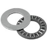
| Product name | Thrust Needle Roller Bearings |
|---|---|
| Part number | BA0619 |
* Orange colored cells in the table below indicate the part numbers used in this example.
Selection criteria
Suitable item to support thrust load
Available sizes
■Thrust Needle Roller Bearings
Material: JIS-SUJ (Bearing Steel)
| (Name No.) | Thrust Needle Roller with Retainer | Thrust Washer x 2 | ||||||||||
|---|---|---|---|---|---|---|---|---|---|---|---|---|
| Hole Dia. | O.D. | Overall Thickness | Hole Dia. | O.D. | Plate Thickness | |||||||
| Tolerance | Tolerance | Tolerance | Tolerance | Tolerance | Tolerance | |||||||
| BA0414 | Ø4 | +0.14 / +0.02 | Ø14 | -0.095 / -0.365 | 2 | 0 / -0.01 | Ø4 | +0.2 / +0.02 | Ø14 | -0.032 / -0.302 | 1 | +0.05 / -0.05 |
| BA0515 | Ø5 | Ø15 | Ø5 | Ø15 | ||||||||
| BA0619 | Ø6 | Ø19 | -0.110 / -0.440 | Ø6 | Ø19 | -0.040 / -0.370 | ||||||
| BA0821 | Ø8 | +0.175 / +0.025 | Ø21 | Ø8 | +0.245 / +0.025 | Ø21 | ||||||
| BA1024 | Ø10 | Ø24 | Ø10 | Ø24 | ||||||||
| BA1226 | Ø12 | +0.212 / +0.032 | Ø26 | Ø12 | +0.302 / +0.032 | Ø26 | ||||||
| BA1528 | Ø15 | Ø28 | Ø15 | Ø28 | ||||||||
| BA1730 | Ø17 | Ø30 | Ø17 | Ø30 | ||||||||
| BA2035 | Ø20 | +0.25/ +0.004 | Ø35 | -0.120 / -0.510 | Ø20 | +0.37 / +0.04 | Ø35 | -0.050 / -0.440 | ||||
| BA2542 | Ø25 | Ø42 | -0.130 / -0.520 | Ø25 | Ø42 | |||||||
| BA3047 | Ø30 | Ø47 | Ø30 | Ø47 | ||||||||
Performance info.
■Load Information of Thrust Needle Roller Bearings
| (Name No.) | Hole Dia. | O.D. | Allowable Rotation Speed (rpm) (Reference) | Mass (g) (Reference) | Basic Dynamic Load Rating Ca kN | Basic Static Load Rating Coa kN |
|---|---|---|---|---|---|---|
| BA0414 | Ø4 | Ø14 | 5200 | 2.7 | 4.4 | 8 |
| BA0515 | Ø5 | Ø15 | 5200 | 2.8 | 4.75 | 9.2 |
| BA0619 | Ø6 | Ø19 | 4700 | 5 | 6.8 | 15.5 |
| BA0821 | Ø8 | Ø21 | 4500 | 6 | 7.8 | 19.4 |
| BA1024 | Ø10 | Ø24 | 4200 | 9 | 9.2 | 25.5 |
| BA1226 | Ø12 | Ø26 | 3700 | 9.9 | 29 | |
| BA1528 | Ø15 | Ø28 | 3200 | 10 | 11.3 | 36 |
| BA1730 | Ø17 | Ø30 | 3000 | 12 | 11.9 | 39.5 |
| BA2035 | Ø20 | Ø35 | 2500 | 15 | 13.1 | 46.5 |
| BA2542 | Ø25 | Ø42 | 2100 | 21 | 14.7 | 58 |
| BA3047 | Ø30 | Ø47 | 1800 | 24 | 16.3 | 70 |

Bearing Lock Nuts
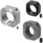
| Product name | Bearing Lock Nuts/Square Type/Coarse Thread |
|---|---|
| Part number | BNGS6 |
* Orange colored cells in the table below indicate the part numbers used in this example.
Selection criteria
Compact nut designed exclusively for tightening the bearings
Available sizes
■Bearing Lock Nuts - Square
| Screw Pitch Type | Material | Hardness | Surface Treatment | Accessory | |
|---|---|---|---|---|---|
| Coarse ・ Fine | EN 1.0038 Equiv. | - | Black Oxide | Set Piece (Copper Alloy) | Set Screw (EN 1.7220 Equiv.) |
| EN 1.1191 Equiv. Thermal Refined | 22 ~ 28HRC | ||||
| EN 1.4301 Equiv. | - | - | Set Screw (EN 1.4301 Equiv. ) | ||
■Sizes and Dimensions
| Thread Dia. x Pitch | Retainer O.D. | External Size | Overall thickness | Set Screw Dia. | |
|---|---|---|---|---|---|
| Coarse Thread | Fine Thread | ||||
| M3 x 0.5 | M3 x 0.35 | Ø4 | □10 | 5.5 | M3 |
| M4 x 0.7 | M4 x 0.5 | Ø5 | |||
| M5 x 0.8 | M5 x 0.5 | Ø9 | □11 | ||
| M6 x 1.0 | M6 x 0.75 | Ø10 | □12 | ||
| M8 x 1.25 | M8 x 1.0 | Ø13 | □14 | 6.5 | |
| M10 x 1.5 | M10 x 1.0 | Ø16 | □17 | 8 | M4 |
| M12 x 1.75 | M12 x 1.0 | Ø17 | □19 | ||
| - | M15 x 1.0 | Ø21 | □22 | 10 | |
| M16 x 2.0 | - | ||||
| - | M17 x 1.0 | ||||
| M20 x 2.5 | M20 x 1.0 | Ø26 | □30 | 13 | |
| M24 x 3.0 | - | Ø33 | □35 | 15 | M5 |
| - | M25 x 1.5 | ||||
| M30 x 3.5 | M30 x 1.5 | Ø39 | □40 | 20 | M6 |
| - | M35 x 1.5 | Ø43 | □45 | ||
| M40 x 1.5 | Ø48 | □49 | 25 | ||
| M50 x 1.5 | Ø61 | □63 | |||

Gussets
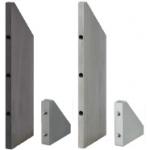
| Product name | Gussets/Tapped Holes/Standard Holes Position/Standard Perpendicularity Type |
|---|---|
| Part number | RBBW30-30-6 |
* Orange colored cells in the table below indicate the part numbers used in this example.
Selection criteria
Best suited for using as an economical reinforcing rib
Available sizes
■Rib - Tapped Hole Fixed Dimensions
| Precision Type | Material | Surface Treatment |
|---|---|---|
| Standard Grade (perpendicularity: 0.05 / 100) ・ Precision Grade (perpendicularity: 0.02 / 100) | EN 1.0038 Equiv. | - |
| Black Oxide | ||
| Electroless Nickel Plating | ||
| EN AW-5052 Equiv. | - | |
| Clear Anodize | ||
| Black Anodize | ||
| EN 1.4301 Equiv. | - |
■Sizes and Dimensions
| Precision Type | Short side | Long side | Thickness / Tapped Hole Dia. | Tapped Hole Depth | ||||||||||||
|---|---|---|---|---|---|---|---|---|---|---|---|---|---|---|---|---|
| 30 | 40 | 50 | 60 | 80 | 100 | EN 1.0038 Equiv. / EN 1.4301 Equiv. | EN AW-5052 Equiv. | |||||||||
| t6 | t9 | t12 | t16 | t6 | t10 | t12 | t16 | |||||||||
| Standard Grade (perpendicularity: 0.05 / 100) ・ Precision Grade (perpendicularity: 0.02 / 100) | 20 | ○ | ○ | ○ | ○ | ○ | M3 | M3 | Diameter x 1.5 | |||||||
| 30 | ○ | M3 | M6 | M3 | M6 | |||||||||||
| ○ | ○ | ○ | ○ | ○ | M5 | M6 | M5 | M6 | ||||||||
| 40 | ○ | ○ | ○ | ○ | ○ | M5 | M6 | M5 | M6 | |||||||
| M6 | M8 | M6 | M8 | |||||||||||||
| 50 | ○ | ○ | ○ | ○ | M5 | M6 | M5 | M6 | ||||||||
| M6 | M8 | M6 | M8 | |||||||||||||
| 60 | ○ | ○ | ○ | M5 | M6 | M5 | M6 | |||||||||
| M6 | M8 | M6 | M8 | |||||||||||||
| 80 | ○ | ○ | M5 | M6 | M8 | M5 | M6 | M8 | ||||||||
| M6 | M8 | M6 | M8 | |||||||||||||
| 100 | ○ | M5 | M6 | M8 | M5 | M6 | M8 | |||||||||
| M6 | M8 | M6 | M8 | |||||||||||||


-
 TERMS AND CONDITIONS FOR USE OF CAD DATA
-
Your access to the CAD data that MISUMI Corporation (hereinafter referred to as the Company) posts on this site (including 3D CAD data, intermediate 3D CAD data and 2D CAD data; hereinafter referred to as the Data) are of products manufactured and/or sold by the Company (hereinafter referred to as the Products) assumes that you have read and accepted these terms and conditions which govern your use of the Data. If you do not agree to these terms and conditions, you must stop using this website and the Data. You must not use the Data for any unlawful purpose or in any manner inconsistent with these terms and conditions.
- 1. CAD Data
- The Data is prepared for assisting the Company's users in the CAD design process by providing dimensions and other Product information. In order to provide the best speed and stability working within this site, the Product drawings were simplified to reduce the size of the Data. For instance, some of the Products are shown without the oil groove shape, screws or spring shape. Also, please be aware that the tolerance, surface roughness and/or chamfer of the Data may vary from the actual Products.
- 2. Disclaimer on Data
- While the Company has carefully prepared the Data, accuracy of the Data is not guaranteed and is subject to the variances as described above. The Company may also modify, add or delete the Data at any time without prior notice. The Company assumes no liability for any direct, indirect, consequential or special damages that you may claim resulted from your use of the Data or any changes to or deletions of the Data regardless of the reason. The Company provides no warranty as to the quality, accuracy, functionality, safety or reliability of the combination of Products and parts. Example applications and combinations of the Products are provided for illustrative purposes only.
- 3. Copyright
-
Copyrights to the content and the Data belong to the Company or the manufacturers of the Products. The said copyright is protected by the Copyright Act and international treaties. The use (including duplication, modification, uploading, posting, transmission, distribution, licensing, sales and publishing) of the Data except for the purpose to use the Data described above without prior approval of the Company is not allowed. The Data cannot be used for any purposes (including sales promotion) except for designing your machine. If you violate this provision or the laws or regulations, the Company may prohibit you from the use of the Data, the Company’s site and/or take legal action. So long as you comply with these terms and conditions, the Company grants to you a non-exclusive, non-transferable, revocable license to access and use the Data for the sole purpose of assisting you in designing machines that incorporate products.
- 4. Disclaimer of Warranty
- ANY AND ALL CONTENT APPEARING ON THIS WEB SITE IS PROVIDED FOR INFORMATIONAL PURPOSES ONLY. THIS WEB SITE, ITS CONTENT AND ITS LINKS ARE PROVIDED ON AN "AS IS" AND "AS AVAILABLE" BASIS AND ARE USED ONLY AT YOUR SOLE RISK, TO THE FULLEST EXTENT PERMISSIBLE BY LAW. THE COMPANY DISCLAIMS ALL WARRANTIES, EXPRESS OR IMPLIED, OF ANY KIND, REGARDING THIS WEB SITE (INCLUDING ITS CONTENT, HARDWARE, SOFTWARE AND LINKS), INCLUDING AS TO FITNESS FOR A PARTICULAR PURPOSE, MERCHANTABILITY, TITLE, NON INFRINGEMENT, RESULTS, ACCURACY, COMPLETENESS, ACCESSIBILITY, COMPATIBILITY, SECURITY AND FREEDOM FROM COMPUTER VIRUS. THE COMPANY WILL NOT BE LIABLE FOR ANY DAMAGES OR LOSSES, INCLUDING DIRECT, INDIRECT, CONSEQUENTIAL, SPECIAL, INCIDENTAL OR PUNITIVE DAMAGES AND/OR LOST PROFITS, IN CONNECTION WITH USE OF THE INTERNET, THIS WEB SITE, ITS CONTENT OR ITS LINKS
Further, the Company will not be liable to you for any failure or delay by the Company to provide access to the Data or any of its obligations under these terms and conditions where such failure or delay is the direct or indirect result of any circumstances beyond the Company's reasonable control (and the Company's obligations will be suspended for the duration of such circumstances). - 5. Policy of Third Parties
- You may be required to separately agree to third party's policies if you use third party software to create or browse the Data or use a third party’s CAD data. In this case, the Company does not assume any responsibility for defects of such CAD data or the software of the third party or violation of their rights. Understand them before use.
CAD Data Download (Unit Assembly)
CAD Data Download: File Format
Cautions on the CAD data
-
Assembly data shows the assembly drawings in the concept design phase. The sole purpose of the data is to explain the structure and functionality of the assembly and is not considered nor to be used as a final design.
You will need to edit the Data so that it meets your specific design conditions. -
The CAD data unit assembly consists of sub-assemblies.
Each sub-assembly unit can be used as it is or can be edited. - The Data for fabricated parts is based on easy-to-edit dimensions and shapes in sketches and histories.
- The Data including the third-part components are made by the Company.
* The part in the frame is a sub-assembly unit.
-
Your access to the CAD data that MISUMI Corporation (hereinafter referred to as the Company) posts on this site (including 3D CAD data, intermediate 3D CAD data and 2D CAD data; hereinafter referred to as the Data) are of products manufactured and/or sold by the Company (hereinafter referred to as the Products) assumes that you have read and accepted these terms and conditions which govern your use of the Data. If you do not agree to these terms and conditions, you must stop using this website and the Data. You must not use the Data for any unlawful purpose or in any manner inconsistent with these terms and conditions.
-

- * Unit assembly CAD data consists of some sub-assemblies.
Each sub-assembly unit can be used as it is or can be edited.
Application Overview
Purpose
- Purpose
- Reducing the thrust load to the motor shaft without using coupling.
- Operation
- Worm gear and wheel are rotated by the motor, and the drum on the shaft wind the wire.
Points for use
- Applicable to thrust load from one direction only.
Target workpiece
- Shape: Block
- Size: W40 x D40 x H25mm
- Weight: 0.3kg
Design Specifications
Operating Conditions or Design Requirements
- Up and down stroke: 30mm
- External size: W123 x D125 x H92mm
Required Performance
- Load: 3N
Selection Criteria for Main Components
- A motor with thrust load of 0.8N is selected to pull up a workpiece of 0.3kg.
Design Evaluation
Verification of main components
- Select the bearing to withstand the load weight.
- Thrust bearing selection
- Conditional values: Diameter of the wire winding part of the drum d1 = 28mm, pitch circle diameter of the worm wheel d2 = 30mm, motor rotational speed z1 = 1200rpm, workpiece mass W = 0.3kg, gravitational acceleration g = 9.8m/s², work movement length l1 = 30mm, friction coefficient on the tooth surface µ = 0.0167, tooth rectangular pressure angle a = 20°, worm gear advance angle y1 = 3.58°, pitch circle diameter of worm gear d3 = 16mm, worm gear rotational speed q1 = 1200mm, basic load rating of thrust bearing c1 = 6.8kN
- Number of revolution necessary for the drum to wind the workpiece n1 is given as follows:
n1 = d1 x π / l1 = 28 x π / 30 = 2.93
Motor rotation time at that time is given by
t1 = d2 x n1 x (60 x z1) = 30 x 2.93 x (60 x 1200) = 4.40t - Net power H1 applied to the worm gear is given by
H1 = W x g x l1 / t1 = 0.3 x 9.8 x 30 / 4.40 = 0.02N = 2.72 x 10⁻⁵ PS - Apparent friction angle on the tooth surface p1 is given by
p1 = tan - 1 (µ) = tan - 1 (0.0167) = 0.957° - Axial thrust load F1 of the worm gear is given by
F1 = F2 / tan (y + p) = 1.432 x H1 x 106 / {tan (y1 + p1) x d3 x q1} x g
= 1.432 x 2.72 x 10-5 x 106 / {tan (3.58 + 0.957) x 16 x 1200} x 9.8
= 0.25N < 6.8kN = c1
⇒No problem
Other Design Consideration
- The bearing, instead of bush, is used although operation turns into low speed rotation because of the worm gear and wheel drive.
- Mounting should be conducted so that no gap exists between the motor bracket, bearing, and the worm gear.
Explore Similar Application Examples
Page
-
/
-


Payment Method


On-Demand Manufacturing
Certificates


Copyright © MISUMI Corporation All Rights Reserved.