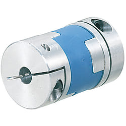
Oldham couplings / grub screw clamping, hub clamping / 1 disc: POM / body: aluminium


(i)Remark
- Please check the content on our website as the PDF does not contain the most up-to-date information.

Part Number
Once your search is narrowed to one product,
the corresponding part number is displayed here.
- Drawing / Specifications
- 3D Preview 3D preview is available after complete configuration
- Part Numbers
- More Information
- Catalog
- Technical Information
Back to the Category Shaft Couplings
Technical Drawing - Claw Couplings
Open the technical drawing in the new window
Available dimensions and tolerances can be found under the tab More information.
Basic Properties (e.g., material, hardness, coating, tolerance) - Claw Couplings
Operating Temperature: -20°C ~ 80°CThe lateral, angular, and axial misalignment values shown are for each occurring individually. When multiple misalignments are occurring simultaneously, the allowable maximum value of each will be reduced to 1/2.
For selection criteria, see >>P.1061.
| TYPE | Material | Surface Treatment | Accessory | |
| Hub | Spacer | Hub | ||
| CPOC | Aluminum Alloy | Polyacetal | Clear Anodize | Clamp Screw |
| CPO | Set Screw | |||
Further specifications can be found under the tab More information.
Composition of a Product Code - Claw Couplings
| Part Number | - | Shaft Bore Dia. d1 | - | Shaft Bore Dia. d2 |
| CPO25 | - | 8 | - | 10 |
| CPOC20 | - | 6 | - | 8 |
Alterations - Claw Couplings
General Information - Claw Couplings
Shaft Coupling Selection Details
- Material: aluminum, aluminum alloy, steel, stainless steel, plastic
- Coupling buffer material: polyacetal, polyurethane, nylon, aluminum bronze, carbon fibre reinforced polymer (CFRP)
- Disc material: stainless steel, polyimide, carbon fibre (carbon)
- Fastening: hub clamping, half shell clamping, threaded pin clamping, clamping sleeve, keyway
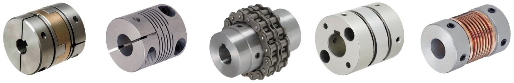
- Design: slit coupling, disc coupling (servo coupling), Oldham coupling, dog coupling, jaw coupling, bellow coupling, metal bellow coupling, elastomer coupling
- ISO tolerances: H8
- Shaft diameter: 1 to 45 mm
- Outer diameter: 6 to 95 mm
- Length: 8.4 to 100 mm
- Offset: angle offset, radial offset, axial offset
Design Overview
Description/Basics
A shaft coupling, also called a compensating coupling, is generally used for the transmission of torque for mechanical engineering. Flexible shaft couplings (non-rigid) can compensate for lateral, axial and angular offsets (misalignment). Therefore, these are common connecting elements between motors and axles/shafts or even ball screws.
There are various types of designs, such as the jaw couplings, disc couplings (servo couplings), slit couplings, bellow couplings, Oldham couplings and many others, which are selected depending on the type of misalignment. You can determine which design is the right one for transmission in your application with the Coupling Selection Method available as a PDF.
When the shaft coupling is professionally installed, the transmission of rotational forces should be slip-free. To do this, the appropriate shaft coupling must be selected depending on the application. Here, it is important to observe the degree of misalignment, the maximum speed of rotation and the permissible torque of the compensation coupling and not to exceed these values during operation. If several misalignments occur at the same time, it is recommended to reduce the maximum value of the specified misalignment by approximately half.
The most commonly used elastomer coupling is the jaw coupling, which consists of a plastic buffer with damping properties. As a result, shocks and vibrations in a drive system can be damped, which protects adjacent components in the transmission of force. Our product range offers you alternative materials for the elastomers. These include among others aluminum bronze and carbon fibre-reinforced plastic.
The different shaft connections on the compensation couplings allow various connection variants for assembly. For this purpose, hub clamping, half shell clamping, slot clamping, threaded pin clamping, chip sleeve and keyways are available.
If a keyway is selected for a MISUMI shaft coupling, it is recommended obtaining the MISUMI machine key, as it is best to combine these.
A shaft coupling can be used for precise positioning. These are often combined together with slide screws or ball screws. A disc clutch (servo coupling) is suitable for this application, since it has a high torsional rigidity.
In addition to the standardized diameter of the shaft bore, MISUMI offers the option LDC and RDC, which allows the drill diameter to be adjusted to the shaft end in 0.1 mm increments.
Application Examples - Claw Couplings
Shaft coupling with servo motor and ball screw
(1) Servo motor, (2) disc coupling (servo coupling), (3) ball screw

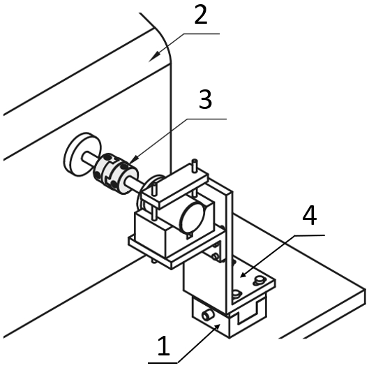
Slit coupling with encoder
(1) Bearing with housing, (2) shaft coupling, (3) motor, (4) axles/shafts
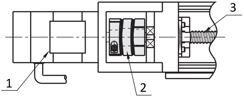
Engine test stand with Oldham coupling
(1) X-axis positioning stage, (2) performance test station, (3) shaft coupling, (4) brackets, L-shaped
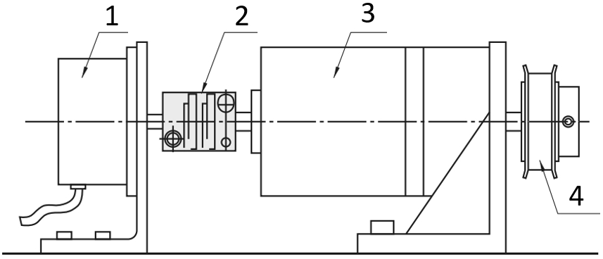
Shaft coupling with motor and gearbox
(1) Motor, (2) Shaft coupling, (3) Conversion/Reducing gears, (4) Timing pulleys / Idlers
Industrial Applications


Part Number:
- In order to open the 3D preview, the part number must be fixed.
3D preview is not available, because the part number has not yet been determined.
| Part Number |
Standard Unit Price
| Minimum order quantity | Volume Discount | RoHS | Allowable Torque Range (N•m) | Shaft Bore Dia. 1 d1 (or d) (mm) | Shaft Bore Dia. 2 d2 (or d) (mm) | O.D. D (mm) | Overall Length (mm) | Allowable Torque (Nm) | Max. Rotational Speed (r/min) | Allowable Lateral Misalignment Range (mm) | Allowable Lateral Misalignment (mm) | Moment of Inertia (kg・m2) | LDC (mm) | RDC (mm) | |
|---|---|---|---|---|---|---|---|---|---|---|---|---|---|---|---|---|---|
- | 1 | 7 Days | 10 | 0.05 to 1.00 | 3 ~ 6.35 | 3 ~ 6.35 | 16 | 18 | 0.7 | 39000 | 0.41 to 1.0 | 1 | 3.2x10⁻⁷ | - | - | ||
- | 1 | 7 Days | 10 | 0.05 to 1.00 | 3 ~ 6.35 | - | 16 | 18 | 0.7 | 39000 | 0.41 to 1.0 | 1 | 3.2x10⁻⁷ | - | 3 ~ 6 | ||
- | 1 | 7 Days | 10 | 0.05 to 1.00 | 3 ~ 6.35 | - | 16 | 18 | 0.7 | 39000 | 0.41 to 1.0 | 1 | 3.2x10⁻⁷ | - | - | ||
- | 1 | 7 Days | 10 | 0.05 to 1.00 | - | 3 ~ 6.35 | 16 | 18 | 0.7 | 39000 | 0.41 to 1.0 | 1 | 3.2x10⁻⁷ | 3 ~ 6 | - | ||
- | 1 | 7 Days | 10 | 0.05 to 1.00 | - | - | 16 | 18 | 0.7 | 39000 | 0.41 to 1.0 | 1 | 3.2x10⁻⁷ | 3 ~ 6 | 3 ~ 6 | ||
- | 1 | 7 Days | 10 | 0.05 to 1.00 | - | - | 16 | 18 | 0.7 | 39000 | 0.41 to 1.0 | 1 | 3.2x10⁻⁷ | 3 ~ 6 | - | ||
- | 1 | 7 Days | 10 | 0.05 to 1.00 | - | 3 ~ 6.35 | 16 | 18 | 0.7 | 39000 | 0.41 to 1.0 | 1 | 3.2x10⁻⁷ | - | - | ||
- | 1 | 7 Days | 10 | 0.05 to 1.00 | - | - | 16 | 18 | 0.7 | 39000 | 0.41 to 1.0 | 1 | 3.2x10⁻⁷ | - | 3 ~ 6 | ||
- | 1 | 7 Days | 10 | 0.05 to 1.00 | - | - | 16 | 18 | 0.7 | 39000 | 0.41 to 1.0 | 1 | 3.2x10⁻⁷ | - | - | ||
- | 1 | 7 Days | 10 | 1.01 to 3.00 | 4 ~ 8 | 4 ~ 8 | 20 | 23 | 1.2 | 31000 | 1.1 to 3.0 | 1.5 | 1.0x10⁻⁶ | - | - | ||
- | 1 | 7 Days | 10 | 1.01 to 3.00 | 4 ~ 8 | - | 20 | 23 | 1.2 | 31000 | 1.1 to 3.0 | 1.5 | 1.0x10⁻⁶ | - | - | ||
- | 1 | 7 Days | 10 | 1.01 to 3.00 | 4 ~ 8 | - | 20 | 23 | 1.2 | 31000 | 1.1 to 3.0 | 1.5 | 1.0x10⁻⁶ | - | 4 ~ 8 | ||
- | 1 | 7 Days | 10 | 1.01 to 3.00 | - | 4 ~ 8 | 20 | 23 | 1.2 | 31000 | 1.1 to 3.0 | 1.5 | 1.0x10⁻⁶ | - | - | ||
- | 1 | 7 Days | 10 | 1.01 to 3.00 | - | - | 20 | 23 | 1.2 | 31000 | 1.1 to 3.0 | 1.5 | 1.0x10⁻⁶ | - | - | ||
- | 1 | 7 Days | 10 | 1.01 to 3.00 | - | - | 20 | 23 | 1.2 | 31000 | 1.1 to 3.0 | 1.5 | 1.0x10⁻⁶ | - | 4 ~ 8 | ||
- | 1 | 7 Days | 10 | 1.01 to 3.00 | - | 4 ~ 8 | 20 | 23 | 1.2 | 31000 | 1.1 to 3.0 | 1.5 | 1.0x10⁻⁶ | 4 ~ 8 | - | ||
- | 1 | 7 Days | 10 | 1.01 to 3.00 | - | - | 20 | 23 | 1.2 | 31000 | 1.1 to 3.0 | 1.5 | 1.0x10⁻⁶ | 4 ~ 8 | - | ||
- | 1 | 7 Days | 10 | 1.01 to 3.00 | - | - | 20 | 23 | 1.2 | 31000 | 1.1 to 3.0 | 1.5 | 1.0x10⁻⁶ | 4 ~ 8 | 4 ~ 8 | ||
- | 1 | 7 Days | 10 | 1.01 to 3.00 | 5 ~ 10 | 5 ~ 10 | 25 | 28 | 2 | 25000 | 1.1 to 3.0 | 2 | 3.0x10⁻⁶ | - | - | ||
- | 1 | 7 Days | 10 | 1.01 to 3.00 | 5 ~ 10 | - | 25 | 28 | 2 | 25000 | 1.1 to 3.0 | 2 | 3.0x10⁻⁶ | - | 5 ~ 10 | ||
- | 1 | 7 Days | 10 | 1.01 to 3.00 | - | 5 ~ 10 | 25 | 28 | 2 | 25000 | 1.1 to 3.0 | 2 | 3.0x10⁻⁶ | 5 ~ 10 | - | ||
- | 1 | 7 Days | 10 | 1.01 to 3.00 | - | - | 25 | 28 | 2 | 25000 | 1.1 to 3.0 | 2 | 3.0x10⁻⁶ | 5 ~ 10 | 5 ~ 10 | ||
- | 1 | 7 Days | 10 | 3.01 to 5.00 | 8 ~ 14 | 8 ~ 14 | 32 | 33 | 4.5 | 19000 | 1.1 to 3.0 | 2.5 | 9.5x10⁻⁶ | - | - | ||
- | 1 | 7 Days | 10 | 3.01 to 5.00 | 8 ~ 14 | - | 32 | 33 | 4.5 | 19000 | 1.1 to 3.0 | 2.5 | 9.5x10⁻⁶ | - | 8 ~ 14 | ||
- | 1 | 7 Days | 10 | 3.01 to 5.00 | 8 ~ 14 | - | 32 | 33 | 4.5 | 19000 | 1.1 to 3.0 | 2.5 | 9.5x10⁻⁶ | - | - | ||
- | 1 | 7 Days | 10 | 3.01 to 5.00 | - | 8 ~ 14 | 32 | 33 | 4.5 | 19000 | 1.1 to 3.0 | 2.5 | 9.5x10⁻⁶ | 8 ~ 14 | - | ||
- | 1 | 7 Days | 10 | 3.01 to 5.00 | - | - | 32 | 33 | 4.5 | 19000 | 1.1 to 3.0 | 2.5 | 9.5x10⁻⁶ | 8 ~ 14 | 8 ~ 14 | ||
- | 1 | 7 Days | 10 | 3.01 to 5.00 | - | - | 32 | 33 | 4.5 | 19000 | 1.1 to 3.0 | 2.5 | 9.5x10⁻⁶ | 8 ~ 14 | - | ||
- | 1 | 7 Days | 10 | 3.01 to 5.00 | - | 8 ~ 14 | 32 | 33 | 4.5 | 19000 | 1.1 to 3.0 | 2.5 | 9.5x10⁻⁶ | - | - | ||
- | 1 | 7 Days | 10 | 3.01 to 5.00 | - | - | 32 | 33 | 4.5 | 19000 | 1.1 to 3.0 | 2.5 | 9.5x10⁻⁶ | - | 8 ~ 14 | ||
- | 1 | 7 Days | 10 | 3.01 to 5.00 | - | - | 32 | 33 | 4.5 | 19000 | 1.1 to 3.0 | 2.5 | 9.5x10⁻⁶ | - | - | ||
- | 1 | 7 Days | 10 | 5.01 to 10.00 | 10 ~ 16 | - | 40 | 32 | 9 | 15000 | 1.1 to 3.0 | 3 | 2.3x10⁻⁵ | - | - | ||
- | 1 | 7 Days | 10 | 5.01 to 10.00 | 10 ~ 16 | - | 40 | 32 | 9 | 15000 | 1.1 to 3.0 | 3 | 2.3x10⁻⁵ | - | 10 ~ 16 | ||
- | 1 | 7 Days | 10 | 5.01 to 10.00 | 10 ~ 16 | - | 40 | 32 | 9 | 15000 | 1.1 to 3.0 | 3 | 2.3x10⁻⁵ | - | - | ||
- | 1 | 7 Days | 10 | 5.01 to 10.00 | - | - | 40 | 32 | 9 | 15000 | 1.1 to 3.0 | 3 | 2.3x10⁻⁵ | 10 ~ 16 | - | ||
- | 1 | 7 Days | 10 | 5.01 to 10.00 | - | - | 40 | 32 | 9 | 15000 | 1.1 to 3.0 | 3 | 2.3x10⁻⁵ | 10 ~ 16 | 10 ~ 16 | ||
- | 1 | 7 Days | 10 | 5.01 to 10.00 | - | - | 40 | 32 | 9 | 15000 | 1.1 to 3.0 | 3 | 2.3x10⁻⁵ | 10 ~ 16 | - | ||
- | 1 | 7 Days | 10 | 5.01 to 10.00 | - | - | 40 | 32 | 9 | 15000 | 1.1 to 3.0 | 3 | 2.3x10⁻⁵ | - | - | ||
- | 1 | 7 Days | 10 | 5.01 to 10.00 | - | - | 40 | 32 | 9 | 15000 | 1.1 to 3.0 | 3 | 2.3x10⁻⁵ | - | 10 ~ 16 | ||
- | 1 | 7 Days | 10 | 5.01 to 10.00 | - | - | 40 | 32 | 9 | 15000 | 1.1 to 3.0 | 3 | 2.3x10⁻⁵ | - | - | ||
- | 1 | 7 Days | 10 | 0.05 to 1.00 | 5 ~ 6 | 5 ~ 6 | 16 | 29 | 0.7 | 39000 | 0.41 to 1.0 | 1 | 5.8x10⁻⁷ | - | - | ||
- | 1 | 7 Days | 10 | 1.01 to 3.00 | 6 ~ 8 | 6 ~ 8 | 20 | 33 | 1.2 | 31000 | 1.1 to 3.0 | 1.5 | 1.5x10⁻⁶ | - | - | ||
- | 1 | 7 Days | 10 | 1.01 to 3.00 | 6 ~ 8 | - | 20 | 33 | 1.2 | 31000 | 1.1 to 3.0 | 1.5 | 1.5x10⁻⁶ | - | - | ||
- | 1 | 7 Days | 10 | 1.01 to 3.00 | - | 6 ~ 8 | 20 | 33 | 1.2 | 31000 | 1.1 to 3.0 | 1.5 | 1.5x10⁻⁶ | - | - | ||
- | 1 | 7 Days | 10 | 1.01 to 3.00 | - | - | 20 | 33 | 1.2 | 31000 | 1.1 to 3.0 | 1.5 | 1.5x10⁻⁶ | - | - | ||
- | 1 | 7 Days | 10 | 1.01 to 3.00 | 6.35 ~ 10 | 6.35 ~ 10 | 25 | 39 | 2 | 25000 | 1.1 to 3.0 | 2 | 4.4x10⁻⁶ | - | - | ||
- | 1 | 7 Days | 10 | 1.01 to 3.00 | 6.35 ~ 10 | - | 25 | 39 | 2 | 25000 | 1.1 to 3.0 | 2 | 4.4x10⁻⁶ | - | - | ||
- | 1 | 7 Days | 10 | 1.01 to 3.00 | 6.35 ~ 10 | - | 25 | 39 | 2 | 25000 | 1.1 to 3.0 | 2 | 4.4x10⁻⁶ | - | 7 ~ 10 | ||
- | 1 | 7 Days | 10 | 1.01 to 3.00 | - | 6.35 ~ 10 | 25 | 39 | 2 | 25000 | 1.1 to 3.0 | 2 | 4.4x10⁻⁶ | - | - | ||
- | 1 | 7 Days | 10 | 1.01 to 3.00 | - | - | 25 | 39 | 2 | 25000 | 1.1 to 3.0 | 2 | 4.4x10⁻⁶ | - | - | ||
- | 1 | 7 Days | 10 | 1.01 to 3.00 | - | - | 25 | 39 | 2 | 25000 | 1.1 to 3.0 | 2 | 4.4x10⁻⁶ | - | 7 ~ 10 | ||
- | 1 | 7 Days | 10 | 1.01 to 3.00 | - | 6.35 ~ 10 | 25 | 39 | 2 | 25000 | 1.1 to 3.0 | 2 | 4.4x10⁻⁶ | 7 ~ 10 | - | ||
- | 1 | 7 Days | 10 | 1.01 to 3.00 | - | - | 25 | 39 | 2 | 25000 | 1.1 to 3.0 | 2 | 4.4x10⁻⁶ | 7 ~ 10 | - | ||
- | 1 | 7 Days | 10 | 1.01 to 3.00 | - | - | 25 | 39 | 2 | 25000 | 1.1 to 3.0 | 2 | 4.4x10⁻⁶ | 7 ~ 10 | 7 ~ 10 | ||
- | 1 | 7 Days | 10 | 3.01 to 5.00 | 8 ~ 14 | 8 ~ 14 | 32 | 45 | 4.5 | 19000 | 1.1 to 3.0 | 2.5 | 1.4x10⁻⁵ | - | - | ||
- | 1 | 7 Days | 10 | 3.01 to 5.00 | 8 ~ 14 | - | 32 | 45 | 4.5 | 19000 | 1.1 to 3.0 | 2.5 | 1.4x10⁻⁵ | - | 8 ~ 14 | ||
- | 1 | 7 Days | 10 | 3.01 to 5.00 | 8 ~ 14 | - | 32 | 45 | 4.5 | 19000 | 1.1 to 3.0 | 2.5 | 1.4x10⁻⁵ | - | - | ||
- | 1 | 7 Days | 10 | 3.01 to 5.00 | - | 8 ~ 14 | 32 | 45 | 4.5 | 19000 | 1.1 to 3.0 | 2.5 | 1.4x10⁻⁵ | 8 ~ 14 | - | ||
- | 1 | 7 Days | 10 | 3.01 to 5.00 | - | - | 32 | 45 | 4.5 | 19000 | 1.1 to 3.0 | 2.5 | 1.4x10⁻⁵ | 8 ~ 14 | 8 ~ 14 | ||
- | 1 | 7 Days | 10 | 3.01 to 5.00 | - | - | 32 | 45 | 4.5 | 19000 | 1.1 to 3.0 | 2.5 | 1.4x10⁻⁵ | 8 ~ 14 | - |
Loading...
Back to the Category Shaft Couplings
Technical Drawing - Claw Couplings
Open the technical drawing in the new window
Specification Tables - Claw Couplings
| Part Number | d1, d2 Selection (d1≤d2) | d3 | L | l | t | F | A | Set Screw / Clamp Screw | Unit Price | ||||||||||||||
| Type | D | M | Tightening Torque (N • m) | ||||||||||||||||||||
| Clamping CPOC | 16 | 5 | 6 | 7 | 29 | 12.5 | 4 | 3 | 5 | M2.5 | 1 | ||||||||||||
| 20 | 6 | 6.35 | 8 | 9 | 33 | 14 | 5 | 6.5 | |||||||||||||||
| 25 | 6.35 | 8 | 10 | 11 | 39 | 16.5 | 6 | 3.8 | 9 | M3 | 1.5 | ||||||||||||
| 32 | 8 | 10 | 11 | 12 | 14 | 14.5 | 45 | 19 | 7 | 4.5 | 11 | M4 | 2.5 | ||||||||||
| *40 | 12 | 14 | 15 | 16 | 17 | 50 | 23 | 4 | 7 | 13 | M5 | 4 | |||||||||||
| Set Screw CPO | 16 | 3 | 4 | 5 | 6 | 6.35 | 7 | 18 | 7 | 4 | 3.5 | - | M3 | 0.7 | |||||||||
| 20 | 4 | 5 | 6 | 6.35 | 8 | 9 | 23 | 9 | 5 | 4.5 | M4 | 1.7 | |||||||||||
| 25 | 5 | 6 | 6.35 | 8 | 9.53 | 10 | 11 | 28 | 11 | 6 | 5.5 | M5 | 4 | ||||||||||
| 32 | 8 | 10 | 12 | 14 | 14.5 | 33 | 13 | 7 | 6.5 | M6 | 7 | ||||||||||||
| *40 | 10 | 12 | 14 | 15 | 16 | 17 | 32 | 14 | 4 | 7 | |||||||||||||
■Characteristic Values
| Part Number | Allowable Torque (N • m) | Angular Misalignment (°) | Lateral Misalignment (mm) | Max. Rotational Speed (r/min) | Moment of Inertia (kg • m2) | Mass (g) | |
| Type | D | ||||||
| CPOC | 16 | 0.7 | 3 | 1.0 | 39000 | 5.8x10⁻⁷ | 12 |
| 20 | 1.2 | 1.5 | 31000 | 1.5x10⁻⁶ | 19 | ||
| 25 | 2.0 | 2.0 | 25000 | 4.4x10⁻⁶ | 36 | ||
| 32 | 4.5 | 2.5 | 19000 | 1.4x10⁻⁶ | 69 | ||
| 40 | 9.0 | 3.0 | 15000 | 4.1x10⁻⁵ | 130 | ||
| CPO | 16 | 0.7 | 3 | 1.0 | 39000 | 3.2x10⁻⁷ | 7 |
| 20 | 1.2 | 1.5 | 31000 | 1.0x10⁻⁶ | 14 | ||
| 25 | 2.0 | 2.0 | 25000 | 3.0x10⁻⁶ | 27 | ||
| 32 | 4.5 | 2.5 | 19000 | 9.5x10⁻⁶ | 50 | ||
| 40 | 9.0 | 3.0 | 15000 | 2.3x10⁻⁵ | 80 | ||
Alterations - Claw Couplings
Basic information
| Series Name | Oldham Type | Allowable Misalignment | Angular Misalignment / Eccentricity | Max. Rotational Speed Range(r/min) | 10,001 to 78,000 |
|---|---|---|---|---|---|
| Body Material | Aluminum | Category | Coupling Main Body | Allowable Angular Misalignment(deg) | 3 |
| Buffer Part Material | Polyacetal | Operating Temperature(°C) | -20::80 |
Configure
Basic Attributes
-
Allowable Torque Range(N•m)
-
Shaft Bore Dia. 1 d1 (or d)(mm)
-
Shaft Bore Dia. 2 d2 (or d)(mm)
-
O.D. D(mm)
-
Overall Length(mm)
-
Allowable Torque(Nm)
-
Max. Rotational Speed(r/min)
-
Allowable Lateral Misalignment Range(mm)
-
Allowable Lateral Misalignment(mm)
-
LDC(mm)
-
RDC(mm)
-
Type
- CPO
- CPOC
-
Filter by CAD data type
- 2D
- 3D
Filter by standard shipping days
-
- All
- 7 Days or Less
Optional Attributes
- The specifications and dimensions of some parts may not be fully covered. For exact details, refer to manufacturer catalogs .
Frequently Asked Questions (FAQ)
-
Question:
Can a claw coupling compensate for an angle?
-
Answer:
As a rule, a claw coupling can compensate for an angular offset. How large this angle may be depends on the respective claw coupling. Here, it is recommended to always refer to the technical information in the data sheet. If there are other misalignments, there is a possibility that the amount of the compensation will be reduced depending on the coupling type. There are notes on this for the shaft couplings.
-
Question:
Which coupling is suitable for a servo motor?
-
Answer:
A disc coupling can be used with a servo motor application. These have a good torsion rigidity, which is necessary for applications with alternating direction of rotation. These couplings are often used in positioning applications. Here, it is recommended to assume the peak torque of the servo motor and to use the compensation factor found on the product page as safety. The permissible torque of the shaft coupling should be higher than the determined value.
-
Question:
What temperature can an elastomeric clutch withstand?
-
Answer:
The temperatures that a claw coupling or Oldham coupling with elastomer buffer can withstand depend on the material used. The permissible temperature is noted for the respective product. However, when designing the shaft coupling, the temperature correction factor should be taken into account in the calculation. You can find it in the shaft coupling selection procedure as a PDF.
-
Question:
Which coupling compensates for a high angular offset?
-
Answer:
A metal bellow coupling can be a possible variant in the case of a high angle offset. This variant of a shaft coupling can compensate an angular offset of up to approx. 2°. This is made possible by the flexible bellow coupling.
Complementary Products
-
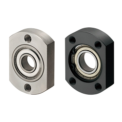 Bearing housings / compact flange / through holes / circlip / deep groove ball bearing / steel, stainless steel / black oxide, nickel plated
MISUMI Standard Price : 19.64 € Shipping Days: Same day
-
 Bearing housings / round flange / counterbore / screwed / deep groove ball bearing, double angular contact ball bearing / steel / black oxided, nickel-plated
MISUMI Standard Price : 538.90 € Shipping Days: 9 Days


MISUMI Unit еxample related to this product


Tech Support
- Technical Support
- Tel:+49 69 668173-0 / FAX:+49 69 668173-360
- Technical Inquiry
Payment Method


On-Demand Manufacturing
Certificates


Copyright © MISUMI Corporation All Rights Reserved.