- Scheduled Maintenance Notice: This site will be unavailable due to scheduled maintenance from 3:00 21/4/2024 to 0:00 (CET) 22/4/2024. We apologize for the inconvenience.
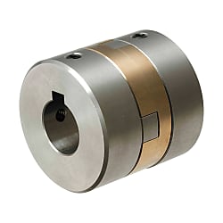
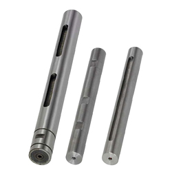
Oldham couplings / fixing selectable / 1 disc: aluminium bronze / body: stainless steel


Part Number
Once your search is narrowed to one product,
the corresponding part number is displayed here.

| Shape | Keywayed Bore | Material | Accessory | |
| d1, d2 (Both Sides) | Hub | Spacer | ||
| Set Screw | MFJGWK | Stainless Steel | Aluminum Bronze | Set Screw |
| Clamping | MFJCGWK | Hex Socket Head Cap Screw | ||
Specifications
| Part Number | - | Shaft Bore Dia. d1 | - | Shaft Bore Dia. d2 |
| MFJGWK45 | - | 15 | - | 20 |
| MFJCGWK55 | - | 22 | - | 25 |
| Part Number | d1, d2 Selection (d1≤d2) | d3 | L | ℓ | F | Set Screw | Unit Price | |||||||||||
| Type | D | M | Tightening Torque (N • m) | |||||||||||||||
| MFJGWK | 45 | 15 | 16 | 18 | 20 | 22.5 | 43.6 | 15 | 7.5 | M 5 | 3.6 | |||||||
| 55 | 20 | 22 | 24 | 25 | 29 | 49.4 | 17 | 8.5 | M 6 | 6.0 | ||||||||
| 70 | 25 | 28 | 30 | 35 | 36 | 57.0 | 20 | 10 | M 8 | 14.0 | ||||||||
■Clamping
| Part Number | d1, d2 Selection (d1≤d2) | d3 | L | ℓ | F | A | Clamp Screw | Unit Price | ||||||||
| Type | D | M | Tightening Torque (N • m) | |||||||||||||
| MFJCGWK | 45 | 15 | 16 | 18 | 20 | 22.5 | 46 | 16.2 | 6 | 14.5 | M5 | *10 | ||||
| 55 | 20 | 22 | 24 | 25 | 29 | 57 | 20.8 | 7 | 18.5 | M6 | *15 | |||||
| Part Number | Allowable Torque (N • m) | Angular Misalignment (°) | Lateral Misalignment (mm) | Static Torsional Spring Constant (N • m/rad) | Max. Rotational Speed (r/min) | Moment of Inertia (kg • m2) | Allowable Axial Misalignment (mm) | Mass (g) | |
| Type | D | ||||||||
| MFJCGWK | 45 | 50 | 1 | 0.8 | 35000 | 5000 | 1.8 x10⁻⁴ | ±0.3 | 450 |
| 55 | 75 | 1.0 | 52000 | 3.3 x10⁻⁴ | ±0.5 | 800 | |||
■Set Screw
| Part Number | Allowable Torque (N • m) | Angular Misalignment (°) | Lateral Misalignment (mm) | Static Torsional Spring Constant (N • m/rad) | Max. Rotational Speed (r/min) | Moment of Inertia (kg • m2) | Allowable Axial Misalignment (mm) | Mass (g) | |
| Type | D | ||||||||
| MFJGWK | 45 | 60 | 1 | 1 | 65000 | 10000 | 1.7 x10⁻⁴ | ±0.3 | 400 |
| 55 | 90 | 1.2 | 100000 | 3.3 x10⁻⁴ | ±0.5 | 700 | |||
| 70 | 160 | 1.6 | 180000 | 11 x10-4 | ±0.6 | 1300 | |||
Alterations
Part Number:
- In order to open the 3D preview, the part number must be fixed.
3D preview is not available, because the part number has not yet been determined.
Part Number
|
|---|
| MFJCGWK45-[15,16,18,20]-[15,16,18,20] |
| MFJCGWK45-[15,16,18,20]-RDC[15-20/1] |
| MFJCGWK45-LDC[15-20/1]-[15,16,18,20] |
| MFJCGWK45-LDC[15-20/1]-RDC[15-20/1] |
| MFJCGWK55-[20,22,24,25]-[20,22,24,25] |
| MFJCGWK55-[20,22,24,25]-RDC[20-25/1] |
| MFJCGWK55-LDC[20-25/1]-[20,22,24,25] |
| MFJCGWK55-LDC[20-25/1]-RDC[20-25/1] |
| MFJGWK45-[15,16,18,20]-[15,16,18,20] |
| MFJGWK45-[15,16,18,20]-RDC[15-20/1] |
| MFJGWK45-LDC[15-20/1]-[15,16,18,20] |
| MFJGWK45-LDC[15-20/1]-RDC[15-20/1] |
| MFJGWK55-[20,22,24,25]-[20,22,24,25] |
| MFJGWK55-[20,22,24,25]-RDC[20-25/1] |
| MFJGWK55-LDC[20-25/1]-[20,22,24,25] |
| MFJGWK55-LDC[20-25/1]-RDC[20-25/1] |
| MFJGWK70-[25,28,30,35]-[25,28,30,35] |
| MFJGWK70-[25,28,30,35]-RDC[25-35/1] |
| MFJGWK70-LDC[25-35/1]-[25,28,30,35] |
| MFJGWK70-LDC[25-35/1]-RDC[25-35/1] |
| Part Number |
Standard Unit Price
| Minimum order quantity | Volume Discount | RoHS | Allowable Torque Range (N•m) | Shaft Bore Dia. 1 d1 (or d) (mm) | Shaft Bore Dia. 2 d2 (or d) (mm) | O.D. D (mm) | Overall Length (mm) | Allowable Torque (Nm) | Max. Rotational Speed (r/min) | Allowable Lateral Misalignment Range (mm) | Allowable Lateral Misalignment (mm) | Allowable Axial Misalignment (mm) | Moment of Inertia (kg・m2) | Shaft Tightening Method | Shaft I.D. d1 Change Hole Dia. [LDC] Specified in 1mm Increment | Shaft I.D. d2 Change Hole Dia. [RDC] Specified in 1mm Increment | |
|---|---|---|---|---|---|---|---|---|---|---|---|---|---|---|---|---|---|---|---|
- | 1 | 9 Days | 10 | 20.01 to 50.00 | 15 ~ 20 | 15 ~ 20 | 45 | 46 | 50 | 5000 | 0.41 to 1.0 | 0.8 | +0.3/-0.3 | 1.8 x10⁻⁴ | Clamping | - | - | ||
- | 1 | 9 Days | 10 | 20.01 to 50.00 | 15 ~ 20 | - | 45 | 46 | 50 | 5000 | 0.41 to 1.0 | 0.8 | +0.3/-0.3 | 1.8 x10⁻⁴ | Clamping | - | 15 ~ 20 | ||
- | 1 | 9 Days | 10 | 20.01 to 50.00 | - | 15 ~ 20 | 45 | 46 | 50 | 5000 | 0.41 to 1.0 | 0.8 | +0.3/-0.3 | 1.8 x10⁻⁴ | Clamping | 15 ~ 20 | - | ||
- | 1 | 9 Days | 10 | 20.01 to 50.00 | - | - | 45 | 46 | 50 | 5000 | 0.41 to 1.0 | 0.8 | +0.3/-0.3 | 1.8 x10⁻⁴ | Clamping | 15 ~ 20 | 15 ~ 20 | ||
- | 1 | 9 Days | 10 | 50.01 to 100.00 | 20 ~ 25 | 20 ~ 25 | 55 | 57 | 75 | 5000 | 0.41 to 1.0 | 1 | +0.5/-0.5 | 3.3 x10⁻⁴ | Clamping | - | - | ||
- | 1 | 9 Days | 10 | 50.01 to 100.00 | 20 ~ 25 | - | 55 | 57 | 75 | 5000 | 0.41 to 1.0 | 1 | +0.5/-0.5 | 3.3 x10⁻⁴ | Clamping | - | 20 ~ 25 | ||
- | 1 | 9 Days | 10 | 50.01 to 100.00 | - | 20 ~ 25 | 55 | 57 | 75 | 5000 | 0.41 to 1.0 | 1 | +0.5/-0.5 | 3.3 x10⁻⁴ | Clamping | 20 ~ 25 | - | ||
- | 1 | 9 Days | 10 | 50.01 to 100.00 | - | - | 55 | 57 | 75 | 5000 | 0.41 to 1.0 | 1 | +0.5/-0.5 | 3.3 x10⁻⁴ | Clamping | 20 ~ 25 | 20 ~ 25 | ||
- | 1 | 9 Days | 10 | 50.01 to 100.00 | 15 ~ 20 | 15 ~ 20 | 45 | 43.6 | 60 | 10000 | 0.41 to 1.0 | 1 | +0.3/-0.3 | 1.7 x10⁻⁴ | Set Screws | - | - | ||
- | 1 | 9 Days | 10 | 50.01 to 100.00 | 15 ~ 20 | - | 45 | 43.6 | 60 | 10000 | 0.41 to 1.0 | 1 | +0.3/-0.3 | 1.7 x10⁻⁴ | Set Screws | - | 15 ~ 20 | ||
- | 1 | 9 Days | 10 | 50.01 to 100.00 | - | 15 ~ 20 | 45 | 43.6 | 60 | 10000 | 0.41 to 1.0 | 1 | +0.3/-0.3 | 1.7 x10⁻⁴ | Set Screws | 15 ~ 20 | - | ||
- | 1 | 9 Days | 10 | 50.01 to 100.00 | - | - | 45 | 43.6 | 60 | 10000 | 0.41 to 1.0 | 1 | +0.3/-0.3 | 1.7 x10⁻⁴ | Set Screws | 15 ~ 20 | 15 ~ 20 | ||
- | 1 | 9 Days | 10 | 50.01 to 100.00 | 20 ~ 25 | 20 ~ 25 | 55 | 49.4 | 90 | 10000 | 1.1 to 3.0 | 1.2 | +0.5/-0.5 | 3.3 x10⁻⁴ | Set Screws | - | - | ||
- | 1 | 9 Days | 10 | 50.01 to 100.00 | 20 ~ 25 | - | 55 | 49.4 | 90 | 10000 | 1.1 to 3.0 | 1.2 | +0.5/-0.5 | 3.3 x10⁻⁴ | Set Screws | - | 20 ~ 25 | ||
- | 1 | 9 Days | 10 | 50.01 to 100.00 | - | 20 ~ 25 | 55 | 49.4 | 90 | 10000 | 1.1 to 3.0 | 1.2 | +0.5/-0.5 | 3.3 x10⁻⁴ | Set Screws | 20 ~ 25 | - | ||
- | 1 | 9 Days | 10 | 50.01 to 100.00 | - | - | 55 | 49.4 | 90 | 10000 | 1.1 to 3.0 | 1.2 | +0.5/-0.5 | 3.3 x10⁻⁴ | Set Screws | 20 ~ 25 | 20 ~ 25 | ||
- | 1 | 9 Days | 10 | - | 25 ~ 35 | 25 ~ 35 | 70 | 57 | 160 | 10000 | 1.1 to 3.0 | 1.6 | +0.6/-0.6 | 11 x10-4 | Set Screws | - | - | ||
- | 1 | 9 Days | 10 | - | 25 ~ 35 | - | 70 | 57 | 160 | 10000 | 1.1 to 3.0 | 1.6 | +0.6/-0.6 | 11 x10-4 | Set Screws | - | 25 ~ 35 | ||
- | 1 | 9 Days | 10 | - | - | 25 ~ 35 | 70 | 57 | 160 | 10000 | 1.1 to 3.0 | 1.6 | +0.6/-0.6 | 11 x10-4 | Set Screws | 25 ~ 35 | - | ||
- | 1 | 9 Days | 10 | - | - | - | 70 | 57 | 160 | 10000 | 1.1 to 3.0 | 1.6 | +0.6/-0.6 | 11 x10-4 | Set Screws | 25 ~ 35 | 25 ~ 35 |
Loading...
More Information
Basic information
| Series Name | Oldham Type | Allowable Misalignment | Angular Misalignment / Eccentricity / Axial Misalignment | Application | Standard |
|---|---|---|---|---|---|
| Max. Rotational Speed Range(r/min) | 4,001 to 10,000 | Features | High Torsional Rigidity / High Torque Type | Body Material | Stainless Steel |
| Category | Coupling Main Body | Allowable Angular Misalignment(deg) | 1 | Buffer Part Material | Aluminum Bronze |
| Operating Temperature(°C) | -20::80 |
Configure
Basic Attributes
-
Allowable Torque Range(N•m)
-
Shaft Bore Dia. 1 d1 (or d)(mm)
-
Shaft Bore Dia. 2 d2 (or d)(mm)
-
O.D. D(mm)
-
Overall Length(mm)
-
Allowable Torque(Nm)
-
Max. Rotational Speed(r/min)
-
Allowable Lateral Misalignment Range(mm)
-
Allowable Lateral Misalignment(mm)
-
Shaft Tightening Method
- Clamping
- Set Screws
-
Shaft I.D. d1 Change Hole Dia. [LDC] Specified in 1mm Increment
-
Shaft I.D. d2 Change Hole Dia. [RDC] Specified in 1mm Increment
-
Type
- MFJCGWK
- MFJGWK
-
Filter by CAD data type
- 2D
- 3D
Filter by standard shipping days
-
- All
- 9 Days or Less
Optional Attributes
- The specifications and dimensions of some parts may not be fully covered. For exact details, refer to manufacturer catalogs .
Complementary Products
-
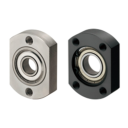 Bearing housings / compact flange / through holes / circlip / deep groove ball bearing / steel, stainless steel / black oxide, nickel plated
MISUMI Standard Price : 19.07 € Shipping Days: Same day
-
 Bearing housings / round flange / counterbore / screwed / deep groove ball bearing, double angular contact ball bearing / steel / black oxided, nickel-plated
MISUMI Standard Price : 523.20 € Shipping Days: 9 Days


MISUMI Unit еxample related to this product


Tech Support
- Technical Support
- Tel:+49 69 668173-0 / FAX:+49 69 668173-360
- Technical Inquiry
Payment Method


On-Demand Manufacturing
Certificates


Copyright © MISUMI Corporation All Rights Reserved.