- Scheduled Maintenance Notice: This site will be unavailable due to scheduled maintenance from 3:00 21/4/2024 to 0:00 (CET) 22/4/2024. We apologize for the inconvenience.
CE01 Contact Crimper【10-100 Pieces Per Package】
Click on this image to zoom in.
Click on this image to zoom in.
- Volume Discount

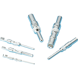
● It is a dedicated contact to be incorporated into the one-touch vibration-resistant and waterproof connector (CE01).
● Select quantity per pack from 10 and 100 (#12 and #8 contacts come only with 10 pieces).

· Perform crimping with the dedicated tool specified by the manufacturer.
Part Number
Once your search is narrowed to one product,
the corresponding part number is displayed here.
Specifications

* Please note that the quantity per pack differs by product.
(#12 and #8 contacts come only with 10 pieces)
| Model | Quantity / Pack | Contact Size | Contact Shape | Type | Applicable Electric Wire | Weight (g) | ||
| AWG Size | Conductor Cross-sectional Area (mm²) | Insulation OD (mm²) | ||||||
| CE01-#08P-C1M | 10 (1 pack = 10 pieces) | #8 | Male | Machine Contact | 10 ~ 8 | 5.5 ~ 8 | Ø7.25 or less | 6.00 |
| CE01-#08P-C2M | 12 ~ 10 | 3.5 ~ 5.5 | 5.70 | |||||
| CE01-#08S-C1M | Female | 10 ~ 8 | 5.5 ~ 8 | 7.00 | ||||
| CE01-#08S-C2M | 12 ~ 10 | 3.5 ~ 5.5 | 6.80 | |||||
| CE01-#12P-C1M | #12 | Male | 16 ~ 12 | 1.25 ~ 3.5 | Ø4.65 or less | 2.20 | ||
| CE01-#12S-C1M | Female | 2.70 | ||||||
| CE01-#16P-1416 | 10 (1 pack = 10 pieces) 100 (1 pack = 100 pieces) | #16 | Male | Press Contact | 14 | 2 | Ø3.8 or less | 0.60 |
| CE01-#16P-1620 | 20 ~ 16 | 0.5 ~ 1.25 | 0.58 | |||||
| CE01-#16P-2024 | 24 ~ 20 | 0.2 ~ 0.5 | 0.56 | |||||
| CE01-#16S-1416 | Female | 14 | 2 | 0.62 | ||||
| CE01-#16S-1620 | 20 ~ 16 | 0.5 ~ 1.25 | 0.60 | |||||
| CE01-#16S-2024 | 24 ~ 20 | 0.2 ~ 0.5 | 0.58 | |||||
| CE01-#20P-C1 | #20 | Male | 22 ~ 18 | 0.3 ~ 0.75 | Ø2.3 or less | 0.23 | ||
| CE01-#20P-C2 | 26 ~ 22 | 0.13 ~ 0.3 | Ø1.2 - 1.7 | 0.24 | ||||
| CE01-#20S-C1 | Female | 22 ~ 18 | 0.3 ~ 0.75 | Ø2.3 or less | 0.26 | |||
| CE01-#20S-C2 | 26 ~ 22 | 0.13 ~ 0.3 | Ø1.2 - 1.7 | 0.24 | ||||
More Information
| Part Number |
Standard Unit Price
| Number of pc(s). included in pkg. | Minimum order quantity | Volume Discount | RoHS | Contact Model | Compatible Wire AWG Size | Contact Shape | Contact Size | Quantity (pcs. / Pack) | |
|---|---|---|---|---|---|---|---|---|---|---|---|
81.57 € | 10 Pieces Per Package | 1 pack | Available | 5 Days | 10 | Machine Contact | 12 ~ 10 | Male | #8 | 10 | |
41.73 € | 10 Pieces Per Package | 1 pack | Available | 5 Days | 10 | Machine Contact | 16 ~ 12 | Male | #12 | 10 | |
66.31 € | 10 Pieces Per Package | 1 pack | Available | 5 Days | 10 | Machine Contact | 16 ~ 12 | Female | #12 | 10 | |
16.76 € | 10 Pieces Per Package | 1 pack | Available | 5 Days | 10 | Press Contact | 20 ~ 16 | Male | #16 | 10 | |
77.69 € | 100 Pieces Per Package | 1 pack | 5 Days | 10 | Press Contact | 20 ~ 16 | Male | #16 | 100 | ||
14.48 € | 10 Pieces Per Package | 1 pack | Available | 5 Days | 10 | Press Contact | 24 ~ 20 | Male | #16 | 10 | |
86.60 € | 100 Pieces Per Package | 1 pack | Available | 5 Days | 10 | Press Contact | 16 ~ 14 | Female | #16 | 100 | |
16.51 € | 10 Pieces Per Package | 1 pack | Available | 5 Days | 10 | Press Contact | 20 ~ 16 | Female | #16 | 10 | |
73.83 € | 100 Pieces Per Package | 1 pack | 5 Days | 10 | Press Contact | 20 ~ 16 | Female | #16 | 100 | ||
8.21 € | 10 Pieces Per Package | 1 pack | Available | 5 Days | 10 | Press Contact | 22 ~ 18 | Male | #20 | 10 | |
48.01 € | 100 Pieces Per Package | 1 pack | 5 Days | 10 | Press Contact | 22 ~ 18 | Male | #20 | 100 | ||
8.21 € | 10 Pieces Per Package | 1 pack | Available | 5 Days | 10 | Press Contact | 26 ~ 22 | Male | #20 | 10 | |
8.21 € | 10 Pieces Per Package | 1 pack | Available | 5 Days | 10 | Press Contact | 22 ~ 18 | Female | #20 | 10 | |
8.21 € | 10 Pieces Per Package | 1 pack | Available | 5 Days | 10 | Press Contact | 26 ~ 22 | Female | #20 | 10 | |
40.42 € | 100 Pieces Per Package | 1 pack | 5 Days | 10 | Press Contact | 26 ~ 22 | Female | #20 | 100 |
Loading...
Protection Circuit Connection Structural Diagram

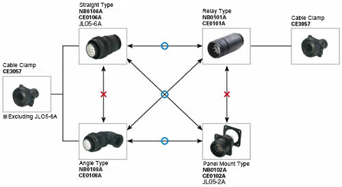
About Compatible Products
NB01 connectors, CE01 connectors, and JL05 connectors are compatible with each other.Combination Method

Material / Finish
| Item | Materials | Finish |
|---|---|---|
| Shell (Body) | Aluminum Alloy | Black Chromate Treatment |
| Insulator | Polyester Resin | UL94V-0, Gray |
| Contact | Copper Alloy | Silver Plating |
| O-ring | Nitrile Rubber | Black |
| Coupling Nut | Aluminum Alloy | Black Chromate Treatment |
| Earth Lug | Steel Alloy | Silver Plating |
| Rear Gasket for Flange | Chloroprene Rubber | Black |
Electrical and Mechanical Properties, Compatible Wires
| Item | Characteristics | |||||||
|---|---|---|---|---|---|---|---|---|
| Rated Current | Contact Size | #20 | #16 | #12 | #8 | |||
| Maximum Value per 1 Piece | 5 A | 13 A | 23 A | 46 A | ||||
| Rated Voltage | Rating Classification | AC (r.m.s) | DC | |||||
| INST | 200 | 250 | ||||||
| A | 500 | 700 | ||||||
| D | 900 | 1,250 | ||||||
| Withstand Voltage | INST | 1,000 VAC (r.m.s) 1 minute | ||||||
| A | 2,000 VAC (r.m.s) 1 minute | |||||||
| D | 2,800 VAC (r.m.s) 1 minute | |||||||
| Insulation Resistance | 5,000 MΩ or more at 500 VDC | |||||||
| Contact Resistance | Contact Size | #20 | #16 | #12 | #8 | |||
| mΩ or less | 8 | 4 | 2 | 0.6 | ||||
| Operating Temperature Range | -55°C ~ +125°C | |||||||
| Waterproofing | IP67 Equivalent | |||||||
| Humidity | Relative Humidity 95% or less | |||||||
| Service Life | 500 Insertions and Removals | |||||||
| NB01 (Solder Type) Compatible Wires (Note 2) |
Contact Size | #16 | #12 | #8 | ||||
| Conductor Cross-sectional Area | 0.75 mm2 or less | 3.5 mm2 or less | 8 mm2 or less | |||||
| AWG Size | 18 or less | 12 or less | 8 or less | |||||
(Note 1) Rated voltage and voltage resistance are shown with rating classification symbols (INST, A; D). Refer as well to the table below.
Contact Arrangement Diagram
| Number of Contacts | 4 | 5 | 7 | 7 | 8 |
|---|---|---|---|---|---|
| Arrangement No. | 22-22 | 18-11 | 20-15 | 24-10 | 22-23 |
| Contact Size | #8 | #12 | #12 | #8 | #12 |
| Contact Arrangement (Note 1) (Note 2) |
 |
 |
 |
 |
 |
| Rating Classification | A | A | A | A | D (4), A (Others) |
| Number of Contacts | 10 | 17 | 19 | 19 | 24 |
|---|---|---|---|---|---|
| Arrangement No. | 18-1 | 20-29 | 18-19A | 22-14 | 24-28 |
| Contact Size | #16 | #16 | #20 | #16 | #16 |
| Contact Arrangement (Note 1) (Note 2) |
 |
 |
 |
 |
 |
| Rating Classification | A (3, 5, 6, 8), INST (Others) |
A | INST | A | INST |
| Number of Contacts | 30 | 37 | 52 | 73 |
| Arrangement No. | 20-30A | 28-21 | 24-52A | 28-73A |
| Contact Size | #20 | #16 | #20 | #20 |
| Contact Arrangement (Note 1) (Note 2) |
 |
 |
 |
 |
| Rating Classification | INST | A | INST | INST |
|---|
(Note 1) View from the male (pin) connector coupling surface.
(Note 2) The ○ in the arrangement table shows the earth terminals (for protection of terminal connections).
Panel Cut Size Drawing

| Compatible Shell Size |
φA ±0.5 |
φB +0.2 -0 |
C ±0.13 |
Mounting Screws (Reference) | Rear Mounting Panel Thickness Limit |
|
|---|---|---|---|---|---|---|
| Inch Screws | Metric Screws | |||||
| 18 | 30.2 | 3.3 | 26.97 | #4-40 | M3 | 3.0 or less |
| 20 | 34.9 | 3.3 | 29.36 | #4-40 | M3 | |
| 22 | 36.6 | 3.3 | 31.75 | #4-40 | M3 | |
| 24 | 39.7 | 4.3 | 34.92 | #6-32 | M4 | |
| 28 | 46.1 | 4.3 | 39.67 | #6-32 | M4 | |
Basic information
| Connector series initials | A / B / C | A/B/C | CE01 | Protection function (environmentally resistant) | Yes |
|---|
Configure
Basic Attributes
-
Contact Model
- Machine Contact
- Press Contact
-
Compatible Wire AWG Size
-
Contact Shape
- Female
- Male
-
Contact Size
- #8
- #12
- #16
- #20
-
Quantity(pcs. / Pack)
- 10
- 100
Filter by standard shipping days
-
- All
- 5 Days or Less
Optional Attributes
- The specifications and dimensions of some parts may not be fully covered. For exact details, refer to manufacturer catalogs .
Tech Support
Payment Method


On-Demand Manufacturing
Certificates


Copyright © MISUMI Corporation All Rights Reserved.