- Lead(mm)
- 2
- 4
- 10
- Axial Play
- Shaft Overall Length L(mm)[150-600/1mm units]
- Shaft End Length F(mm)
- 10
[10-18/1mm units] - Shaft Dia. P(Ø)
- 6
- Screw Shaft Surface Treatment
- Shaft End Dimension (Fixed, Configurable)
- Shaft Dia. P(φ)
- 5
- 6
- CAD
- 3D
- Est. shipping days
- All
- Within 7 working days
- Within 9 working days
Ball screws / compact flange / diameter 10 / pitch 2, 4, 10 / C7, C10 / steel / phosphated / 58-62HRC

Part number:
possible part numbers found.Outline drawing and specifications table
Dimensional Drawing

View X-X
* Collar Included (1 pc.) "M" Material: EN 1.1191 Equiv. "S" Surface Treatment: Black Oxide
BSST·BSSR (K)·BSSZ (K) 1004

View X-X
* Collar Included (1 pc.) "M" Material: EN 1.1191 Equiv. "S" Surface Treatment: Black Oxide
BSSR (K) 1010

View X-X
* Collar Included (1 pc.) "M" Material: EN 1.1191 Equiv. "S" Surface Treatment: Black Oxide
| Nut | Type | Accuracy | Shaft Dia. | Lead | Screw Shaft | Nut | |||||
| Type | Standard | F, P Configurable | Grade | [M] Material | [H] Hardness | [S] Surface Treatment | [M] Material | [H] Hardness | [S] Surface Treatment | ||
| Standard Nut | BSST | — | C7 | 10 | 4 | EN 1.1203 Equiv. | Induction hardened 56 to 62HRC | — | EN 1.7264 Equiv. | Carburized 58 to 62HRC | [ ! ] Phosphate Conversion Coating |
| BSSR | BSSRK | C10 | 2·4·10 | Phosphate Conversion Coating | Phosphate Conversion Coating | ||||||
| BSSZ | BSSZK | 4 | — | ||||||||
Specification Table
| Part Number | — | L | — | F | — | P |
| BSSZ1004 BSSZK1004  BSSR1004L BSSR1004L BSSR1004G BSSR1004G | — — — — | 200 370 370 370 | ||||
| — | F15 | — | P6 | |||
| (L Type Greased) | ||||||
| (G Type Greased) | ||||||
| Nut Type | Accuracy Grade | Part Number | 1 mm Increments | Y | Ball Dia. | Ball Center Dia. | Screw Root Dia. | Number of Circuits | Basic Load Rating | Axial Play Clearance | Twisting Direction | |||||
| Type | Screw Shaft O.D. | Lead | L | * F | * P | C (Dynamic) kN | Co (Static) kN | |||||||||
| Standard Nut | C10 | BSSR | 10 | 02 | 150 to 585 | 10 | 6 | L-54 | 1.5875 | 10.3 | (8.4) | 2.5 turns Single Row | 1.7 | 3 | 0.05 or Less | Right |
| BSSRK | 10 to 18 | 5·6 | L- (44+F) | |||||||||||||
| C7 | BSST | 04 | 10 | 6 | L-54 | 2.3812 | 10.6 | (7.8) | 2.3 | 4.8 | 0.03 or Less | |||||
| C10 | BSSR | 150 to 600 | 0.05 or Less | |||||||||||||
| BSSZ | ||||||||||||||||
| BSSRK | 10 to 18 | 5·6 | L- (44+F) | |||||||||||||
| BSSZK | ||||||||||||||||
| BSSR | 10 | 150 to 585 | 10 | 6 | L-54 | 2.3812 | 10.6 | (7.8) | 1.5 turns | 1.85 | 3.2 | |||||
| BSSRK | 10 to 18 | 5·6 | L- (44+F) | Single Row | ||||||||||||
| * F and P are configurable for BSSRK and BSSZK only. [!] F ≤ P × 3. [!] Y (Nut Motion Range) > (Nut Overall Length). kgf = N × 0.101972 | ||||||||||||||||
Alterations
| Part Number | — | L | — | F | — | P | — | (FC·KC, etc.) |
| BSSR1004 | — | 270 | — | SC7 |
| Alterations | Code | Spec. | Alterations | Code | Spec. | |||||||
No Machining on Both Shaft Ends [ ! ]A nut is mounted to the temporary shaft before the product is shipped. | WNC | Does not machine any of the both shaft ends. Ordering Code WNC-S20-F80 [ ! ] Annealing may lower hardness on the annealed area + 25 mm fore and aft. [ ! ]S+F ≤ L/2 [ ! ]L- (S+F) ≤ Y+50 [ ! ] On the annealed area + 25 mm fore and aft, axis run-out may be larger than indicated by the Catalog standard. | Keyway on Fixed Side Shaft End | KC | Adds a keyway on the fixed side shaft end. [NG] P = 5 is not possible. KC = 1 mm Increments Ordering Code KC5 [ ! ]2 ≤ KC ≤ P × 3 KC ≤ F-1 | |||||||
No Machining on Support Side Shaft End | NC | No machining added on the support side shaft end. Ordering Code NC | Keyway on Fixed Side Shaft End | KLC | The position of keyway on fixed side shaft end can be specified. (Keyway dimensions are the same as KC.) [NG] P = 5 is not possible. K, S = 1 mm Increments Ordering Code KLC-K5-S2 [ ! ]3 ≤ K+S ≤ P × 3 K+S ≤ F-2 | |||||||
Ball Nut Orientation Reversed
| RLC | Changes the nut direction. Ordering Code RLC | Flat Machined on Fixed Side Shaft End | SC | Adds a flat on the fixed side shaft end. SC = 1 mm Increments Ordering Code SC7 [ ! ]5 ≤ SC ≤ P × 3 SC ≤ F-1 | |||||||
No Retaining Ring Groove on Support Side Shaft End | RNC | No Retaining Ring Groove on Support Side Shaft End. Ordering Code RNC [NG] Combination with FC is not available. | Flat Machined on Fixed Side Shaft End (2 Locations) JIS−SWC SGC  | JIS−SWC SGC | Adds two flats on the fixed side shaft end. JIS−SWC: 90° Position SGC: 120° Position 1 mm Increments Ordering Code JIS−SWC7 [ ! ]5 ≤ JIS−SWC·SGC ≤ P × 3 JIS−SWC·SGC ≤ F-1 | |||||||
Change Support Side Shaft End Length | FC | Changes the length of the support side shaft end. FC = 1 mm Increments Ordering Code FC20 [ ! ]11 ≤ FC ≤ 20 [ ! ] Y dimension is shortened. | Installing Special Temporary Shaft | TAS | Dedicated Temporary Shafts suitable for Ball Screws are installed. When removing Nut from Screw Shaft, always use Special Temporary Shaft. | |||||||
Wrench Flats on Fixed Side Incomplete Hardened Area | SZC | Adds wrench flats on the fixed side shaft end. Ordering Code SZC [ ! ] Ball bearings will fall out, if the ball nut crosses the wrench flats. | ||||||||||


[ ! ] Specify an alteration position to be 2 mm or more away from the stepped part. (Refer to the diagram in Caution (1))
[ ! ] When selecting multiple alterations, the distance between machined areas should be 2 mm or more. (Refer to the diagram in Caution (2))
[ ! ] When flat machining, wrench flats, square chamfering and keyway alterations are combined with each other, their orientations will be random.
(Refer to the diagram in Caution (3))
[ ! ] Do not specify multiple alterations in such a way that they overlap with each other in the rotating direction on the same shaft. (Refer to the diagram in Caution (4))
[ ! ] When two or more features are specified on a shaft, their orientation will be random.
| Caution (1) Specify the alteration portion to be 2 mm or more away from the stepped part.  | Caution (2) 2 mm or more is required for the clearance between multiple alterations.  | Caution (3) When the multiple alterations are combined with each other, their orientations are random and thus, are not always aligned in a linear arrangement. (One example of this is shown in the diagram below.)  | Caution (4) Do not specify multiple alterations in such a way that they overlap with each other on the same shaft. (Any diagram as shown below is not acceptable.)  |
Part number list
| Part number |
|---|
Unit price (excluding VAT)(Unit price including VAT) | Standard shipping days |
|---|
- ( - ) | 7 working days |
- ( - ) | 9 working days |
- ( - ) | 9 working days |
- ( - ) | 7 working days |
- ( - ) | 9 working days |
- ( - ) | 9 working days |
- ( - ) | 7 working days |
- ( - ) | 9 working days |
- ( - ) | 9 working days |
- ( - ) | 7 working days |
- ( - ) | 9 working days |
- ( - ) | 9 working days |
- ( - ) | 7 working days |
- ( - ) | 9 working days |
- ( - ) | 9 working days |
- ( - ) | 7 working days |
- ( - ) | 9 working days |
- ( - ) | 9 working days |
- ( - ) | 7 working days |
- ( - ) | 9 working days |
- ( - ) | 9 working days |
- ( - ) | 7 working days |
- ( - ) | 9 working days |
- ( - ) | 9 working days |
- ( - ) | 7 working days |
- ( - ) | 7 working days |
- ( - ) | 9 working days |
- ( - ) | 9 working days |
More Information
Outline and specifications
Specifications/Overview
[ ! ] Mounting surface of BSST ball nut flange is not surface-treated.
[ ! ] Filled with lithium soap based grease (Alvania Grease S2 made by Showa Shell Sekiyu K.K).
[!] Alternative grease types available.
" ! " Cautions: Do not let the nuts overrun or remove the nuts from the screw shafts.
It may cause the balls to fall out or damage the ball recirculation parts.
[ ! ] The collar included with this product should be installed in the same position as indicated with the "*Collar" text on the drawing.
In addition, the collar included with the Support Unit product should be installed and tightened on the nut side of the ball screw.
[ ! ] Note that, when a ball screw shaft or ball screw nut is tilted, it may be fallen out by its own weight.
| Ball Screw Part Number | Recommended Support Unit | |||||||
| Type | Screw Shaft O.D. | Lead | Part Number | Shape | Fixed Side | Support Side | ||
| Type | No. | |||||||
| BSST BSSR BSSZ | 10 | 02 04 10 | BRW | 8S | Round | ○ | ||
| BUR | 6 | ○ | ||||||
| BSW | 8S | Square | ○ | |||||
| BUN | 8 | ○ | ||||||
| Ball Screw Part Number | Recommended Nut Bracket | ||||
| Type | Screw Shaft O.D. | Lead | Part Number | ||
| Type | No. | ||||
| BSST BSSR BSSZ | 10 | 02 | BNFB BNFM BNFR BNFA | 1002R | |
| 04 | 1004R | ||||
| 10 | 1010R | ||||
General Information - Ball Screws

Ball Screw Selection Details
- Material: steel
- Coatings: uncoated, LTBC coating, phosphate conversion coating
- Heat treatment: up to 62HRC
- Precision category: C3, C5, C7, C10
- Precision classes: precision class, standard class
- Slope: 1 to 32 mm
- Outer diameter: 6 to 32 mm
- Length (mm): 100 to 2000
- Nut shape: round flange, square flange, compact flange, block shape
Description/Basics
Ball screws are intended for converting rotary motion to linear motion. This can also be done in reverse order from linear to rotary motion. With the ball screws, this is achieved extremely precisely due to their low play. In mechanical engineering, the ball thread drive is an indispensable feature and is indispensable in precision applications. These work in horizontal and vertical orientation, allowing to shift, raise and lower devices.
The ball screws are often driven by motors and shaft couplings, or manually via rotary/crank handles.
When utilising a keyway, it is recommended using a machine key, as these can be combined excellently due to the manufacturing tolerances.
For a smooth process, it is recommended installing the ball screw with a fixed bearing and a floating bearing. This ensures that the ball screw does not bend due to compression and generate vibrations. For this purpose, MISUMI offers the right support units drives in various designs. For more information on how to install ball screws, see the Installation Instructions available as a PDF.
Ball screw nuts are available in different shapes. These enable versatile utilisation, even in confined spaces. Due to their high precision, the ball screws can also provide a high level of repeatability that is necessary in precise positioning applications. These can be utilised, for example, for measuring devices or in 3D printing. It is recommended to use a pre-stressed ball screw for highly precise applications. Due to the pre-tensioning, the axial play is almost zero unlike a conventional ball screw. In addition, MISUMI offers single axis actuators (locating units) for such applications, which as drives are already equipped with precise ball screws.
In smaller applications, a slide screw or a so-called miniature screw drive can be used. Due to their design, these are very compact, but suitable for lower axial loads.
If very high forces occur, a lead screw could also be considered.
Which ball screw is the right one for your application must be calculated based on the existing factors and influences. You can use the selection Ball Screws that is available as a PDF for this purpose. You can also find the service life calculation in this link.
Application Examples - Ball Screws
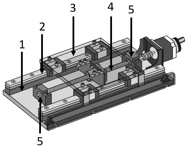
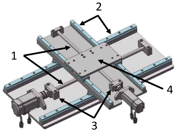
Application example for positioning stages
(1) Linear guide accessories, (2) Standard linear guide, (3) Table plate (meviy), (4) Ball screw, (5) Support units
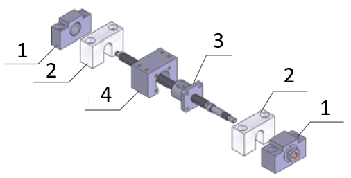
Application example for the ball screw
(1)) Support units, (2) Ball screw nut stops, (3) Ball screw, (4) Ball screw nut mountings
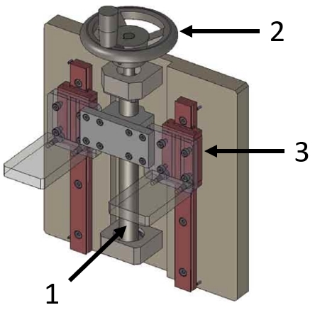
Application example for a lifting device
(1) Ball screw, (2) Standard linear guide, (3) Support units, (4) Table top (meviy)
(1) Ball screw, (2) Standard linear guide, (3) Support units, (4) Table top (meviy)
Industrial Applications


