- Allowable Torque Range(N•m)
- Shaft Bore Dia. 1 d1 (or d)(mm)
- 14
- 15
- 16
- 18
- 20
- 22
- 25
- 26
- 28
- 30
- 35
- 38
- Shaft Bore Dia. 2 d2 (or d)(mm)
- 14
- 15
- 16
- 18
- 20
- 22
- 25
- 26
- 28
- 30
- 35
- 38
- O.D. D(mm)
- 44
- 55
- 70
- Overall Length(mm)
- 46
- 57
- 77
- Max. Rotational Speed Range(r/min)
- Allowable Torque(Nm)
- 30
- 45
- 80
- Max. Rotational Speed(r/min)
- 8000
- 10000
- 12000
- Allowable Lateral Misalignment Range(mm)
- Allowable Lateral Misalignment(mm)
- 1
- 1.5
- 2
- Shaft Bore Shape
- Shaft Tightening Method
- Shaft I.D. d1 Change Hole Dia. [LDC] Specified in 0.1mm Increment[14-38/0.1]
- Shaft I.D. d2 Change Hole Dia. [RDC] Specified in 0.1mm Increment[14-38/0.1]
- Type
- CAD
- 2D
- 3D
- Est. shipping days
- All
- Within 7 working days
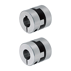
Oldham couplings / fixing selectable / 1 disc: POM / body: aluminium


Part number:
possible part numbers found.Outline drawing and specifications table
Back to the Category Shaft Couplings
Technical Drawing - Claw Couplings
Available dimensions and tolerances can be found under the tab More information.
Basic Properties (e.g., material, hardness, coating, tolerance) - Claw Couplings
Operating Temperature: -20°C ~ 80°CTolerances for d1 and d2 are values before slit machining.
The lateral, angular, and axial misalignment values shown are for each occurring individually. When multiple misalignments are occurring simultaneously, the allowable maximum value of each will be reduced to 1/2. When multiple misalignments are occurring simultaneously, the allowable maximum value of each will be reduced to 1/2.
For the selection criteria and alignment procedures, see >> P.1061
| Shape | Standard Bore | Keywayed Bore | Material | Accessory | |||
| d1 (One Side) | d2 (One Side) | d1, d2 (Both Sides) | Hub | Spacer | |||
| Set Screw | MFJ | - | - | MFJWK | Aluminum Alloy | Polyacetal | Set Screw |
| Clamping | MFJC | MFJCLK | MFJCRK | MFJCWK | Hex Socket Head Cap Screw | ||
Further specifications can be found under the tab More information.
Composition of a Product Code - Claw Couplings
| Part Number | - | Shaft Bore Dia. d1 | - | Shaft Bore Dia. d2 |
| MFJ44 | - | 15 | - | 20 |
| MFJCWK70 | - | 22 | - | 35 |
Alterations - Claw Couplings
General Information - Claw Couplings
Shaft Coupling Selection Details
- Material: aluminum, aluminum alloy, steel, stainless steel, plastic
- Coupling buffer material: polyacetal, polyurethane, nylon, aluminum bronze, carbon fibre reinforced polymer (CFRP)
- Disc material: stainless steel, polyimide, carbon fibre (carbon)
- Fastening: hub clamping, half shell clamping, threaded pin clamping, clamping sleeve, keyway
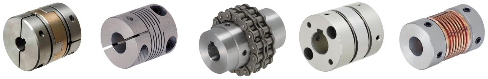
- Design: slit coupling, disc coupling (servo coupling), Oldham coupling, dog coupling, jaw coupling, bellow coupling, metal bellow coupling, elastomer coupling
- ISO tolerances: H8
- Shaft diameter: 1 to 45 mm
- Outer diameter: 6 to 95 mm
- Length: 8.4 to 100 mm
- Offset: angle offset, radial offset, axial offset
Design Overview
Description/Basics
A shaft coupling, also called a compensating coupling, is generally used for the transmission of torque for mechanical engineering. Flexible shaft couplings (non-rigid) can compensate for lateral, axial and angular offsets (misalignment). Therefore, these are common connecting elements between motors and axles/shafts or even ball screws.
There are various types of designs, such as the jaw couplings, disc couplings (servo couplings), slit couplings, bellow couplings, Oldham couplings and many others, which are selected depending on the type of misalignment. You can determine which design is the right one for transmission in your application with the Coupling Selection Method available as a PDF.
When the shaft coupling is professionally installed, the transmission of rotational forces should be slip-free. To do this, the appropriate shaft coupling must be selected depending on the application. Here, it is important to observe the degree of misalignment, the maximum speed of rotation and the permissible torque of the compensation coupling and not to exceed these values during operation. If several misalignments occur at the same time, it is recommended to reduce the maximum value of the specified misalignment by approximately half.
The most commonly used elastomer coupling is the jaw coupling, which consists of a plastic buffer with damping properties. As a result, shocks and vibrations in a drive system can be damped, which protects adjacent components in the transmission of force. Our product range offers you alternative materials for the elastomers. These include among others aluminum bronze and carbon fibre-reinforced plastic.
The different shaft connections on the compensation couplings allow various connection variants for assembly. For this purpose, hub clamping, half shell clamping, slot clamping, threaded pin clamping, chip sleeve and keyways are available.
If a keyway is selected for a MISUMI shaft coupling, it is recommended obtaining the MISUMI machine key, as it is best to combine these.
A shaft coupling can be used for precise positioning. These are often combined together with slide screws or ball screws. A disc clutch (servo coupling) is suitable for this application, since it has a high torsional rigidity.
In addition to the standardized diameter of the shaft bore, MISUMI offers the option LDC and RDC, which allows the drill diameter to be adjusted to the shaft end in 0.1 mm increments.
Application Examples - Claw Couplings
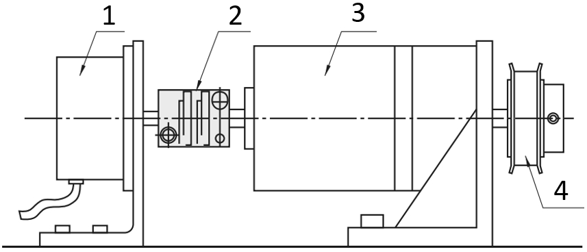
Shaft coupling with servo motor and ball screw
(1) Servo motor, (2) disc coupling (servo coupling), (3) ball screw

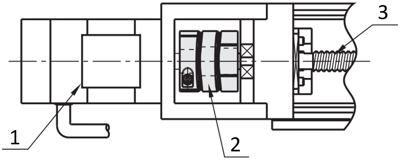
Slit coupling with encoder
(1) Bearing with housing, (2) shaft coupling, (3) motor, (4) axles/shafts
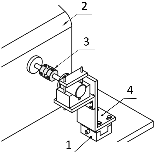
Engine test stand with Oldham coupling
(1) X-axis positioning stage, (2) performance test station, (3) shaft coupling, (4) brackets, L-shaped
Shaft coupling with motor and gearbox
(1) Motor, (2) Shaft coupling, (3) Conversion/Reducing gears, (4) Timing pulleys / Idlers
Industrial Applications


Part number list
| Part number |
|---|
Unit price (excluding VAT)(Unit price including VAT) | Standard shipping days |
|---|
- ( - ) | 7 working days |
- ( - ) | 7 working days |
- ( - ) | 7 working days |
- ( - ) | 7 working days |
- ( - ) | 7 working days |
- ( - ) | 7 working days |
- ( - ) | 7 working days |
- ( - ) | 7 working days |
- ( - ) | 7 working days |
- ( - ) | 7 working days |
- ( - ) | 7 working days |
- ( - ) | 7 working days |
More Information
Basic information
Outline and specifications
Back to the Category Shaft Couplings
Technical Drawing - Claw Couplings
Specification Tables - Claw Couplings
| Part Number | d1, d2 Selection (d1≤d2) | d3 | L | ℓ | F | Set Screw | Unit Price | ||||||||||||||
| Type | D | M | Tightening Torque (N • m) | MFJ | MFJWK | ||||||||||||||||
| MFJ MFJWK | 44 | 14 | 15 | 16 | 18 | 20 | 22 | 22.5 | 46 | 15 | 7.5 | M 6 | 7.0 | ||||||||
| 55 | 18 | 20 | 22 | 25 | 26 | 28 | 57 | 19 | 9.5 | M 8 | 15.0 | ||||||||||
| 70 | 22 | 25 | 28 | 30 | 35 | 38 | 39 | 77 | 25 | 12.5 | M10 | 30.0 | |||||||||
■Clamping
| Part Number | d1, d2 Selection (d1≤d2) | d3 | L | ℓ | F | A | Clamp Screw | Unit Price | |||||||||||||
| Type | D | M | Tightening Torque (N • m) | MFJC | MFJCLK MFJCRK | MFJCWK | |||||||||||||||
| MFJC MFJCLK MFJCRK MFJCWK | 44 | 14 | 15 | 16 | 18 | 20 | 22.5 | 46 | 15 | 7.5 | 14.5 | M5 | *8.4 | ||||||||
| 55 | 18 | 20 | 22 | 25 | 28 | 57 | 19 | 9.5 | 17 | M6 | *14.4 | ||||||||||
| 70 | 22 | 25 | 28 | 30 | 35 | 39 | 77 | 25 | 12.5 | 24 | M8 | *30.0 | |||||||||
| Part Number | Allowable Torque (N • m) | Angular Misalignment (°) | Lateral Misalignment (mm) | Static Torsional Spring Constant (N • m/rad) | Max. Rotational Speed (r/min) | Moment of Inertia (kg • m2) | Allowable Axial Misalignment (mm) | Mass (g) | |||
| Type | D | Set Screw | Clamping | ||||||||
| Set Screw MFJ MFJWK | Clamping MFJC MFJCLK MFJCRK MFJCWK | 44 | 30 | 26 | 2 | 1 | 1500 | 12000 | 4 x10⁻⁵ | ±0.5 | 140 |
| 55 | 45 | 40 | 1.5 | 2800 | 10000 | 11 x10-5 | ±0.6 | 260 | |||
| 70 | 80 | 72 | 2 | 4800 | 8000 | 40 x10-5 | ±0.8 | 450 | |||
Alterations - Claw Couplings