- Inner Diameter(mm)[4-25/0.01mm units]
- Outer Diameter(mm)
- 10
- 12
- 15
- 18
- 20
- 22
- 25
- 26
- 30
- 35
- Material
- Steel
- EN 1.2510 Equiv.
- Surface Treatment
- P Dimension Fixed, L Selectable/P L Dimension Configurable
- Number of Fixing Holes
- Length L(mm)[5-50/0.1mm units]
- Type
- CAD
- 2D
- 3D
- Est. shipping days
- All
- Within 14 working days
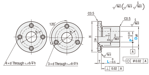
Flanged drill bushes / round flange / bore +0.01 / steel, stainless steel / 50HRC-60HRC

Part number:
possible part numbers found.Outline drawing and specifications table
4-Point Stopper
3-Point Stopper
| [M] Material | [S] Surface Treatment | [H] Hardness | Type | |||
| P Fixed and L Selectable | P, L Configurable | |||||
| 4-Point Stopper | 3-Point Stopper | 4-Point Stopper | 3-Point Stopper | |||
| EN 1.2510 Equiv. | — | * Treated Hardness 56 to 60HRC | JBY | JBT | JBYF | JBTF |
| Black Oxide | — | — | JBYFB | — | ||
| Electroless Nickel Plating | JBYM | — | JBYFM | JBTFM | ||
| EN 1.4301 Equiv. | — | — | — | — | JBYFS | — |
| EN 1.4037 Equiv. | — | Treated Hardness: 50 to 55 HRC | — | — | JBYFC | — |
Specification Table
| Part Number | — | P | — | L |
| JBY6 JBSF20 JBOR10 JBN10 | — — | P13.00 P5.0 | — — — — | 12 L30.0 L8 10 |
| Part Number | L Selection | R | H | T | dg6 | A | d | d1 | h | ||||||||||
| Type | P | ||||||||||||||||||
| JBY JBYM JBT | 5 | 8 | 10 | 12 | 16 | 1 | 25 | 5 | 10 | −0.005 | 17 | 3.3 | 6.5 | 3.5 | |||||
| * 1 6 | 8 | 10 | 12 | 16 | −0.014 | ||||||||||||||
| * 1 8 | 10 | 12 | 16 | 20 | 2 | 28 | 12 | −0.006 | 20 | ||||||||||
| * 1 10 | 36 | 6 | 15 | −0.017 | 26 | 4.5 | 8 | 4.5 | |||||||||||
| * 1 12 | 12 | 16 | 20 | 25 | 30 | 18 | |||||||||||||
| 13 | 12 | 16 | 20 | 25 | 30 | 40 | 22 | −0.007 | 30 | ||||||||||
| * 1 15 | 12 | 16 | 20 | 25 | 30 | 44 | 25 | −0.020 | 34 | ||||||||||
| 16 | 16 | 20 | 25 | 30 | 35 | 26 | |||||||||||||
| * 1 20 | 3 | 56 | 8 | 30 | 42 | 6.6 | 11 | 6.5 | |||||||||||
| 25 | 20 | 25 | 30 | 35 | 40 | 60 | 35 | −0.009 | 46 | ||||||||||
| −0.025 | |||||||||||||||||||
■Round Flanged
| Mass (g) Ref. Value | ||
| P | L | EN 1.2510 Equiv. |
| 5 | 8 | 3.70 |
| 10 | 4.63 | |
| 12 | 5.55 | |
| 16 | 7.40 | |
| 6 | 8 | 3.16 |
| 10 | 3.95 | |
| 12 | 4.74 | |
| 16 | 6.32 | |
| 8 | 10 | 4.94 |
| 12 | 5.92 | |
| 16 | 7.90 | |
| 20 | 9.87 | |
| 10 | 10 | 7.71 |
| 12 | 9.26 | |
| 16 | 12.34 | |
| 20 | 15.43 | |
| 12 | 12 | 13.33 |
| 16 | 17.77 | |
| 20 | 22.21 | |
| 25 | 27.77 | |
| 30 | 33.32 | |
| 13 | 12 | 23.32 |
| 16 | 31.10 | |
| 20 | 38.87 | |
| 25 | 48.59 | |
| 30 | 58.31 | |
| 15 | 12 | 29.62 |
| 16 | 39.49 | |
| 20 | 49.36 | |
| 25 | 61.70 | |
| 30 | 74.04 | |
| 16 | 16 | 41.46 |
| 20 | 51.83 | |
| 25 | 64.79 | |
| 30 | 77.74 | |
| 35 | 90.70 | |
| 20 | 16 | 49.36 |
| 20 | 61.70 | |
| 25 | 77.13 | |
| 30 | 92.55 | |
| 35 | 107.98 | |
| 25 | 20 | 74.04 |
| 25 | 92.55 | |
| 30 | 111.06 | |
| 35 | 129.57 | |
| 40 | 148.08 |
■P and L Configurable [!] L + T ≤ P × 3.0
| Part Number | P 0.01 mm Increments | L 0.1 mm Increments | R | H | T | A | d | d1 | h | ||
| Type | dg6 | ||||||||||
| Round Flanges, 4-Point Stopper JBYF JBYFB JBYFM JBYFS JBYFC Round Flanges, 3-Point Stopper JBTF JBTFM | 10 | −0.005 −0.014 | 4.00 to 6.50 | 5.0 to 15.0 | 1 | 25 | 5 | 17 | 3.3 | 6.5 | 3.5 |
| 12 | −0.006 −0.017 | 6.00 to 8.50 | 2 | 28 | 20 | ||||||
| 15 | 8.00 to 10.50 | 10.0 to 35.0 | 36 | 6 | 26 | 4.5 | 8 | 4.5 | |||
| 18 | 10.00 to 12.50 | ||||||||||
| 20 | −0.007 −0.020 | 12.00 to 13.50 | 40 | 30 | |||||||
| 22 | 12.00 to 13.50 | ||||||||||
| 25 | 13.00 to 15.50 | 44 | 34 | ||||||||
| 26 | 15.00 to 16.50 | ||||||||||
| 30 | 16.00 to 20.50 | 12.0 to 50.0 | 3 | 56 | 8 | 42 | 6.6 | 11 | 6.5 | ||
| 35 | −0.009 −0.025 | 20.00 to 25.00 | 60 | 46 | |||||||
Alterations
| Part Number | — | P | — | L | — | (TKC·RC·FC·RH) |
| JBNF15 | — | P10.0 | — | L10.0 | — | TKC |
| JBTF20 | — | P12.0 | — | L12.0 | — | FC |
| Alteration | Code | Spec. | ||||||||||||||||||||||||
T Tolerance Change  | TKC | Changes the T tolerance from general tolerance to ±0.01. Ordering Code TKC [ NG ] P Fixed and L Selectable, Compact Flange | ||||||||||||||||||||||||
I.D. Radius R  | RC | Machines Radius R on both sides. D10→R1 D12 to 26→R2 D30·35→R3 Ordering Code RC [ ! ] If (D-P)/2 ≤ 2, then R < 2 | ||||||||||||||||||||||||
 | FC | Cuts one side of flange. Ordering Code FC [ ! ] Applicable to JBTF and
|
Part number list
| Part number |
|---|
Unit price (excluding VAT)(Unit price including VAT) | Standard shipping days |
|---|
- ( - ) | 14 working days |
- ( - ) | 14 working days |
- ( - ) | 14 working days |
- ( - ) | 14 working days |
- ( - ) | 14 working days |
- ( - ) | 14 working days |
- ( - ) | 14 working days |
- ( - ) | 14 working days |
- ( - ) | 14 working days |
- ( - ) | 14 working days |
More Information
Basic information
[Features] Round flange bushing for positioning pins. [Change aid] Change T dimension tolerance, add inner diameter R, cut on one side, change inner diameter R.
Caution
- Please check the content on our website as the PDF does not contain the most up-to-date information.
Outline and specifications
General Information - Flanged Drill Bushes
Selection between drill bushings / positioning bushings / centering bushings
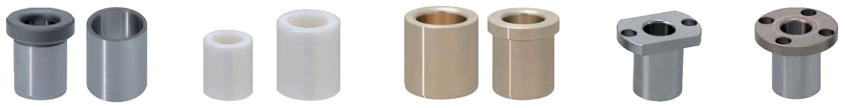
- Material: steel, stainless steel, brass, ceramics
- Coatings: untreated, nickel-plated, burnished
- Hardness: 50HRC to 62HRC
- Fastening: with notch, mounting bracket, with dowel pin, pressed-in
- Inside diameter shape: round, oval
- ISO tolerances: g6, h6, m6, n6, p6, 0/-0.2, 0/-0.01
- Inside diameter: 2 mm to 35 mm
- Outside diameter: 5 mm to 48 mm
- Length: 3 mm to 60 mm
Here to the drill bushings Overview as PDF
Description / Basics
A drill bushing is intended for precise centering, positioning and guidance of drills. They can be used in drilling rigs or for multi-spindle drilling heads as well as a drilling jig. Therefore, it is possible to create an accurate and recurring bore at the same position in one component. In addition, through the guide the drill bushing protects the drill from breakage. The most common bushings are the collar drill bushing according to DIN 172 and the cylindrical drill bushing according to DIN 179.
Drill bushings and collar drill bushings are available in a variety of fastening types. They can be pressed in or secured with a semi-circular notch in the collar of the plug-in fulcrum pins. Since it is not pressed, this has the advantage of quick interchangeability. MISUMI also offers the special form of a flanged bushing with mounting flange.
Collar bushings with oval bores are also available at MISUMI. These are provided with a semi-circular notch in the collar, which, in combination with a dowel pin, serves to align the collar drill bushing.
Drill bushings are often used as positioning bushings or centering bushings.
Due to the rounded insertion of the drill bushing, it can serve as a joining opening for centering pins or height adjusting pins.
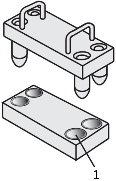
Application Examples - Flanged Drill Bushes

Example for using a centering bolt/centering bushing with collar
(1) Locating pin, (2) Bushings for fixtures

Example for using a centering bolt/centering bushing
(1) Locating pin , (2) Bushings for fixtures, (3) Mounting plate
Industrial Applications


