- Screw Turn Direction
- Right Screw
- Right-hand Thread
- Left-hand Thread
- Material
- Surface Treatment
- Thread Nominal D(φ)
- 12
- 14
- 16
- 18
- 20
- 22
- 25
- Pitch(mm)
- 2
- 3
- 4
- 5
- Shaft Overall Length L(mm)[80-1200/1mm units]
- S(mm)[2-100/1mm units]
- CAD
- 2D
- Est. shipping days
- All
- Within 7 working days
- Within 12 working days
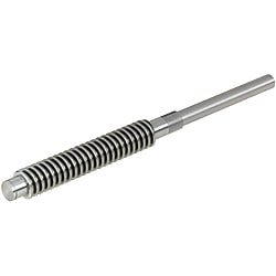
Lead Screws For Support Units DIN 103
Part number:
possible part numbers found.Outline drawing and specifications table
Dimensional Drawing
 | Right-Hand Screw / Left-Hand Screw *For D = 20, 22, 25 | Standard Chevron Dimensions H = 1.866P, H1 = 0.5P, d2 = d - 0.5P d1 = d-P, D = d, D2 = d2, D1 = d1 Thread d: O.D. d1: Root Dia. d2: Effective Dia. Tapped D: Root Dia. D1: I.D. D2: Effective Dia. P: Pitch H1: Engage Height | |||||||||||||||
| |||||||||||||||||
·No hardening treatment is applied. | Lead Screw Accuracy
Dimensional tolerances are regulated for Tr standard. Refer to the table below for Lead Screw Specifications. | h7 Tolerance (V,Q)
| Unspecified Dimensional Tolerances
| ||||||||||||||||||||||||||||||||||||||||||||||||||||||||||||||||||||||||||||
Specification Table
| Part Number | — | L | — | S |
| MTWK20 | — | 800 | — | S90 |
| Part Number | 1 mm Increments | F | R | B | T | Q | A | M × Pitch (Fine) | E | D | Pitch P | [Reference] Lead Screw Areas Minimum Length | ||
| Type | D | L | S | |||||||||||
| Right-Hand Screw / Left-Hand Screw MTWK MTWLK MTWBK MTWBLK RMTWK RMTWLK MTSWK MTSWLK | 12 | 80 to 1000 | 2 ≤ S ≤ 80 | 10 | 8 | 7 | 26 | 8 | 11 | 8 × 1.0 | 6 | 12 | 2 | 22 |
| 14 | 12 | 10 | 8 | 29 | 10 | 12 | 10 × 1.0 | 8 | 14 | 3 | 22 | |||
| 16 | 100 to 1200 | 2 ≤ S ≤ 95 | 12 | 12 | 8 | 29 | 12 | 12 | 12 × 1.0 | 10 | 16 | (3) | 26 | |
| 18 | 150 to 1200 | 12 | 12 | 8 | 29 | 12 | 12 | 12 × 1.0 | 10 | 18 | 4 | 31 | ||
| 20 | 2 ≤ S ≤ 100 | 12 | 15 | 9 | 34 | 15 | 14 | 15 × 1.0 | 12 | 20 | 4 | 31 | ||
| [ ! ] D dimension 22 is not available for MTSWK. [ ! ] D dimensions 22 and 25 are not available for MTSWLK. | 22 | 12 | 15 | 9 | 34 | 15 | 14 | 15 × 1.0 | 12 | 22 | 5 | 40 | ||
| 25 | 12 | 15 | 9 | 34 | 15 | 14 | 15 × 1.0 | 12 | 25 | (5) | 40 | |||
[ ! ] This product is a single thread screw and therefore the pitch P = lead.
[ ! ] Sizes in ( ) are outside the Tr standard, but the machining accuracy of all sizes conforms to the Tr standard.
[!] M Thread Tolerance Zone Class: 6 g
[!] Recommended Grease: Lithium soap-based grease No. 2 (Please wipe off the antirust oil before applying.)
| Shaft Dia. | Pitch | Thread Shaft Effective Dia. | Screw Shaft Minor Dia. (MIN) | Thread Shaft Lead Angle | Screw Shaft Runout (Max.) | ||||||||||
| Shaft Overall Length | |||||||||||||||
| Up to 125 | 126 Up to 200 | 201 Up to 315 | 316 Up to 400 | 401 Up to 500 | 501 Up to 630 | 631 Up to 800 | 801 Up to 1000 | 1001 Up to 1250 | 1251 Up to 1600 | 1601 Up to 2000 | |||||
| 8 | 1.5 | 7.25 | (5.9) | 3° 46′ | 0.1 | 0.14 | 0.21 | 0.27 | 0.35 | - | - | - | - | - | - |
| 10 | 2 | 9 | (7.2) | 4° 03′ | 0.09 | 0.12 | 0.16 | 0.21 | 0.27 | 0.35 | 0.46 | 0.58 | |||
| 12 | 2 | 11 | (9.2) | 3° 19′ | |||||||||||
| 14 | 3 | 12.5 | (10.1) | 4° 22′ | 0.09 | 0.11 | 0.13 | 0.16 | 0.2 | 0.25 | 0.32 | 0.42 | - | - | - |
| 16 | 2 | 15 | (13.18) | 2° 25′ | 0.55 | 0.73 | 1 | ||||||||
| 3 | 14.5 | (12.1) | 3° 46′ | ||||||||||||
| 18 | 4 | 16 | (13.1) | 4° 33′ | - | ||||||||||
| 20 | 2 | 19 | (17.18) | 1° 55′ | |||||||||||
| 4 | 18 | (15.1) | 4° 03′ | ||||||||||||
| 22 | 5 | 19.5 | (16.1) | 4° 40′ | - | 0.09 | 0.11 | 0.13 | 0.16 | 0.19 | 0.23 | 0.3 | 0.38 | 0.5 | 0.69 |
| 25 | 5 | 22.5 | (19) | 4° 03′ | |||||||||||
| 28 | 5 | 25.5 | (22) | 3° 34′ | |||||||||||
| 32 | 6 | 29 | (24.5) | 3° 46′ | |||||||||||
| 36 | 6 | 33 | (28.5) | 3° 19′ | - | 0.11 | 0.11 | 0.11 | 0.13 | 0.15 | 0.17 | 0.22 | 0.27 | 0.34 | 0.46 |
| 40 | 6 | 37 | (32.5) | 2° 57′ | |||||||||||
| 50 | 8 | 46 | (40.4) | 3° 10′ | |||||||||||

Alterations
| Part Number | — | L | — | S | — | (NAR·RC·FE·SE·ME·MR·ZE·KE) | ||
| MTWK20 | — | 800 | — | S90 | — | KE0 | — | C30 |
| Alterations | No Retaining Ring Groove on Support Side Shaft End | No Machining on Support Side | Flat Machining | Wrench Flats | Coarse Tapping | Square Chamfering | Keyway | |||||||||||||||||||||||||||||||||||||||||||||||||||
 |  |  |  |  |  |  | ||||||||||||||||||||||||||||||||||||||||||||||||||||
| Code | NAR (R Part) | RC (R Part) | FE (E Part) | SE (E Part) | MR (Left Side), ME (E Part) | ZE (E Part) | KE (E Part) | |||||||||||||||||||||||||||||||||||||||||||||||||||
| Spec. | No retaining ring machining performed on the R part for the support side end. Ordering Code NAR | No machining performed on the R part. Ordering Code RC [NG] Combination with other R part alteration is not available. | FE, FW, FY = 0.5 mm Increments FE = Applied on E part Ordering Code FE5−FW10−FY1 [ ! ]FY ≤ 1.0 [ ! ] FE = 0, or FE ≥ 2 [ ! ]3 ≤ FW ≤ 20 | SE, SW, SY = 1 mm Increments SE = Applied on E part Ordering Code SE3−SW10−SY7 [ ! ]SW ≥ E−2 [ ! ]3 ≤ SY ≤ 20 [ ! ] SE = 0, or FE ≥ 2 | ME = Applied on E part MR = Applied on R part and left end face Ordering Code ME6
[NG]When combining with an other alteration, do not specify this alteration in such a way that the shaft end thickness becomes less than 1 mm.  | A = 1 mm Increments ZE = Applied on E part Ordering Code ZE12−W10−A8 [ ! ] Can be combined with Tapped Hole machining only on the same shaft. [ ! ]5 ≤ A ≤ 20 [ ! ] ZE = E Specified
| KE,C = 1 mm Increments [ ! ]C ≤ 60 [ ! ]KE ≥ 2 [ ! ] When KE = 0,  KE = Applied on E part [ ! ] Applicable to D dimension 16 or more
| |||||||||||||||||||||||||||||||||||||||||||||||||||
[!]Specify an alteration position to be 2 mm or more away from the stepped part. (Refer to the diagram in Caution (1))
[!] When adding multiple alterations, there must be 2 mm or more clearance between each machined part. (Refer to the diagram in Caution (2))
[!]When flat machining, wrench flats, square chamfering and keyway alterations are combined with each other, their orientations will be random. (Refer to the diagram in Caution (3))
[!] Do not specify multiple alterations in such a way that they overlap with each other in the rotating direction on the same shaft. (Refer to the diagram in Caution (4))
[ ! ] When two or more alterations are specified on a shaft, they may not be machined due to correlation.
| Caution (1) Specify the alteration portion to be 2 mm or more away from the stepped part .  | Caution (2) 2 mm or more is required for the clearance between multiple alterations .  | Caution (3) When the multiple alterations are combined with each other, their orientations are random and thus, are not always aligned in a linear arrangement. (One example of this is shown in the diagram below.)  For Alterations A and B added to the same shaft, as shown in the diagram above, their orientations are random and thus, there are some cases where they are not aligned in a linear arrangement. | Caution (4) Do not specify multiple alterations in such a way that they overlap with each other on the same shaft. (Any diagram as shown below is not acceptable.) 
|
Part number list
| Part number |
|---|
Unit price (excluding VAT)(Unit price including VAT) | Standard shipping days |
|---|
- ( - ) | 7 working days |
- ( - ) | 7 working days |
- ( - ) | 7 working days |
- ( - ) | 7 working days |
- ( - ) | 7 working days |
- ( - ) | 7 working days |
- ( - ) | 7 working days |
- ( - ) | 7 working days |
- ( - ) | 7 working days |
- ( - ) | 7 working days |
- ( - ) | 7 working days |
- ( - ) | 7 working days |
- ( - ) | 7 working days |
- ( - ) | 7 working days |
- ( - ) | 7 working days |
- ( - ) | 7 working days |
- ( - ) | 7 working days |
- ( - ) | 7 working days |
- ( - ) | 7 working days |
- ( - ) | 7 working days |
- ( - ) | 7 working days |
- ( - ) | 7 working days |
- ( - ) | 7 working days |
- ( - ) | 7 working days |
- ( - ) | 7 working days |
- ( - ) | 7 working days |
- ( - ) | 7 working days |
- ( - ) | 7 working days |
- ( - ) | 7 working days |
- ( - ) | 7 working days |
- ( - ) | 7 working days |
- ( - ) | 7 working days |
- ( - ) | 7 working days |
- ( - ) | 7 working days |
- ( - ) | 7 working days |
- ( - ) | 7 working days |
- ( - ) | 7 working days |
- ( - ) | 7 working days |
- ( - ) | 7 working days |
- ( - ) | 12 working days |
- ( - ) | 12 working days |
- ( - ) | 12 working days |
- ( - ) | 12 working days |
- ( - ) | 12 working days |
- ( - ) | 12 working days |
- ( - ) | 12 working days |
- ( - ) | 12 working days |
- ( - ) | 12 working days |
- ( - ) | 12 working days |
- ( - ) | 12 working days |
- ( - ) | 12 working days |
- ( - ) | 12 working days |
- ( - ) | 12 working days |
More Information
Basic information
DIN 103
Caution
- Please check the content on our website as the PDF does not contain the most up-to-date information.
Outline and specifications
App. Example
■Slide Base Transfer Unit | ■Recommended Configuration This unit allows the slide base for workpiece/fixture loading to be position-adjusted by manually rotating its lead screws. A dedicated lead screw, bearing unit and stopper clamp are combined in a set. The unit can support radial and axial loads, and can be constructed more economically in a compact manner . Also, position indicators can be easily mounted. ■Combined Parts Details
* The following two types of alterations are combined on the lead screw shaft for fixing the handle.
|