Configure
- Hole Position
- External Dimension A(mm)[25-200/0.1mm units]
- External Dimension B(mm)
- 15
- 16
- 20
- 22
- 25
- 32
- 38
- 50
- 60
- 65
- 75
- 100
- 125
[10-200/0.1mm units] - Plate Thickness t(mm)
- 5
- 6
- 8
- 9
- 10
- 12
- 15
- 16
- 19
- 20
- CAD
- 2D
- 3D
- Est. shipping days
- All
- Within 7 working days
- Within 9 working days
- Within 11 working days
Flat Bar/Rolled Aluminum Mounting Plate/Bracket, Dimension, HRNQA HUNQA

Part number:
possible part numbers found.Outline drawing and specifications table
HRNQA (B Dim. Selectable)
HUNQA (B Dim. Configurable)
[ ! ] Hole pitch dimension tolerance conforms to JIS B 0405 Class m.
[NG] For B Dim. Selectable Type (HR□□□), EN AW-5052 Equiv. cannot be specified
HUNQA (B Dim. Configurable)

HRNQA
HUNQA
[ ! ] Hole pitch dimension tolerance conforms to JIS B 0405 Class m.
[!] Orientation of Slotted Holes can be changed (Refer to the "Alterations" section.)
[ ! ] C0.2 to C0.5, unless otherwise specified
[!] Green colored parameters can be omitted. If the parameter setting is omitted, the holes will be evenly distributed about the center.
[ ! ] C0.2 to C0.5, unless otherwise specified
[!] Green colored parameters can be omitted. If the parameter setting is omitted, the holes will be evenly distributed about the center.
■Hole Type Selection Chart
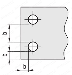
■Machining Limits
There are machining limits for thickness between hole and hole or between hole and end face.
(Example: "b" on the drawing below)
| Hole Type | Tapped Hole | Bolt Hole | Counterbore Front | Counterbore Back | Through Hole | |||||||||||||||||||||||||||||||||||||||||||||||||||
| Code | M·MA | N・NA | Z·ZF | ZB | DA | |||||||||||||||||||||||||||||||||||||||||||||||||||
| Shape Diagram |  |  |  |  |  | |||||||||||||||||||||||||||||||||||||||||||||||||||
| Machining Specifications | Tap effective length maximum M, MA × 2 [ ! ] When T ≥ M × 3, tap pilot might not go through . |
|
| |||||||||||||||||||||||||||||||||||||||||||||||||||||
■Machining Limits
There are machining limits for thickness between hole and hole or between hole and end face.
(Example: "b" on the drawing below)

| Part Number | [M] Material | [S] Surface Treatment | |
| Type | Material Symbol | ||
| B Dim. Selectable (Flat Bars) HRNQA B Dim. Configurable (Width Configurable Flat Bars / Rolled Aluminum) HUNQA | SC | EN 1.1191 Equiv. (cold drawn) | — |
| SCB | Black Oxide | ||
| SCM | Electroless Nickel Plating | ||
| AM | EN AW-5052 Equiv. | — | |
| AMW | Anodize (Clear) | ||
| AMB | Anodize (Black) | ||
| SU | EN 1.4301 Equiv. | — | |
Specification Table
| Part Number | — | A | — | B | — | T | — | X | — | V | — | Y | — | W | — | Hole Specification (1) Code / Nominal Dia. | — | K | — | L | — | H | — | D | — | F | — | S | — | G | — | Hole Specification (2) Code / Nominal Dia. | — | J | ||
| Type | — | Material Symbol | ||||||||||||||||||||||||||||||||||
| HRMQA | — | SC | — | A80 | — | B50 | — | T6 | — | X10 | — | Y25 | — | M6 | — | L60 | — | MA6 | ||||||||||||||||||
| HUMCC | — | AMB | — | A100 | — | B80 | — | T10 | — | X15 | — | V70 | — | Y10 | — | W60 | — | Z6 | — | L50 | — | H40 | — | D30 | — | F50 | — | MA6 | ||||||||
| Type | Part Number | 0.1 mm Increments | B | T | X | Y | Hole Specification (1) | K | L | Hole Specification (2) | |||||
| Type | Material Symbol | A | Code | Nominal Dia. | Code | Nominal Dia. | DA | 0.5 mm | |||||||
| B Dim. Selectable | HRNQA | SC SCB SCM | 25.0 ~ 200.0 | 16 22 25 32 38 50 60 75 100 125 | 6 9 (10) 12 16 19 | Configurable 0.1 mm Unit | N [ ! ] M Z [ ! ] [ ! ] For the machining dimensions , see Hole Type Selection Chart. | 0 (No Hole) 3 4 5 6 8 10 12 14 16 | Configurable 0.1 mm Unit [ ! ]K ≤ N × 5 | NA [ ! ] MA ZF [ ! ] ZB [ ! ] [ ! ] For the machining dimensions , see Hole Type Selection Chart. | 0 (No Hole) 3 4 5 6 8 10 12 14 16 | DA | 3 ~ 30 | ||
| SU | 15 20 25 32 38 50 65 100 125 | ||||||||||||||
| B Dim. Configurable | HUNQA | SC SCB SCM SU | 25.0 ~ 200.0 | 15.0 to 150.0 (0.1 mm Increments) | 6 9 (10) 12 16 19 | ||||||||||
| AM AMW AMB | 10.0 to 200.0 (0.1 mm Increments) | 5 6 8 10 12 15 20 | |||||||||||||
| [NG] T10 is not selectable for SC(□) [NG] For SC(□) with B = 16 or 22, T19 is not selectable | [NG] For SU with B = 15, T10 to 19 are not selectable [NG] For SU with B = 20, T19 is not selectable | ||||||||||||||
Alteration
| Alterations | Corner Cut Change | Slotted Hole Angle Change |
 |  | |
| Code | CC | RC |
| Spec. | Changes corner cuts. CC = 1 mm Increments [ ! ]1 ≤ CC ≤ 50 Specifying Method Add CC to the end of a Part Number. Example: ... -CC10 | Slotted holes are changed as shown above. [!] Note the dimensional relationship Specifying Method Add RC to the end of a Part Number. (Example) ... -RC |
Part number list
Number of items
| Part number |
|---|
Unit price (excluding VAT)(Unit price including VAT) | Standard shipping days |
|---|
- ( - ) | 7 working days |
- ( - ) | 9 working days |
- ( - ) | 9 working days |
- ( - ) | 7 working days |
- ( - ) | 7 working days |
- ( - ) | 11 working days |
- ( - ) | 11 working days |
- ( - ) | 7 working days |
- ( - ) | 9 working days |
- ( - ) | 9 working days |
- ( - ) | 7 working days |
Catalog
Loading...