Configure
- External Dimension A(mm)[30-150/0.1mm units]
- External Dimension B(mm)[10-150/0.1mm units]
- Plate Thickness t(mm)[5-20/0.1mm units]
- CAD
- 2D
- 3D
- Est. shipping days
- All
- Within 7 working days
- Within 9 working days
- Within 11 working days
6 Surface Milling Machine Plates/Brackets. Side Hole Type. VFMPA

Part number:
possible part numbers found.Outline drawing and specifications table
Dimensional Drawing
VFMPA

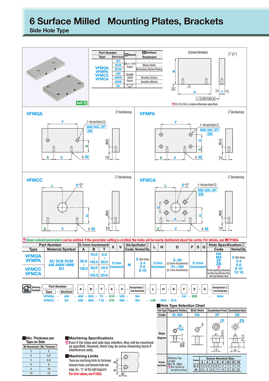
[ ! ] Hole pitch dimension tolerance conforms to JIS B 0405 Class m.

[ ! ] Hole pitch dimension tolerance conforms to JIS B 0405 Class m.
[ ! ] C0.2 to C0.5, unless otherwise specified
[ ! ]Green colored parameters can be omitted.
If the parameter setting is omitted, the holes will be evenly distributed about the center.
[ ! ]Green colored parameters can be omitted.
If the parameter setting is omitted, the holes will be evenly distributed about the center.
■Hole Type Selection Chart
Hole Type | Tapped Hole | Bolt Hole | Counterbore Front | Counterbore Back | |||||||||||||||||||||||||||||||||||
Code | M·MA | N・NA | Z·ZF | ZB | |||||||||||||||||||||||||||||||||||
Shape Diagram |  |  |  |  | |||||||||||||||||||||||||||||||||||
Machining Specifications | Effective Tap Length Max. M, MA × 2 [ ! ] When T ≥ M and MA × 3, tap pilot might not go through. |
| |||||||||||||||||||||||||||||||||||||
■Min. Thickness per Taps on Side
| ■Machining Limits There are machining limits for thickness between hole and hole or between hole and end face. (Example: "b" on the drawing right) ■Machining Specifications [ ! ] Even if the holes and side taps interfere, they will be machined as specified. However, there may be some remaining burrs if interference exits. |  |
| Part Number | [M] Material | [S] Surface Treatment | |
| Type | Material Symbol | ||
| VFMPA | SC | EN 1.1206 Equiv. | — |
| SCB | Black Oxide | ||
| SCM | Electroless Nickel Plating | ||
| AM | EN AW-5052 Equiv. | — | |
| AMW | Anodize (Clear) | ||
| AMB | Anodize (Black) | ||
| SU | EN 1.4301 Equiv. | — | |
Specification Table
| Part Number | — | A | — | B | — | T | — | X | — | V | — | Hole Specification (1) Code / Nominal Dia. | — | L | — | H | — | D | — | F | — | S | — | G | — | Hole Specification (2) Code / Nominal Dia. | ||
| Type | — | Material Symbol | ||||||||||||||||||||||||||
| VFMPA | — | AM | — | A50 | — | B30 | — | T5 | — | X10 | — | V30 | — | M4 | — | F40 | — | S20 | — | MA4 | ||||||||
| Part Number | 0.1 mm Increments | X | V | Hole Specification (1) | F | S | G | Hole Specification (2) | |||||
| Type | Material Symbol | A | B | T | Code | Nominal Dia. | Code | Nominal Dia. | |||||
| VFMPA | SC SCB SCM AM AMW AMB SU | 30.0 ~ 150.0 | 10.0 ~ 150.0 | 5.0 ~ 20.0 | Configurable 0.1 mm Unit | M | 0 (No Hole) 3 4 5 6 8 10 | 0.1 mm Increments Unit | NA MA ZF ZB [ ! ] For the machining dimensions , see Hole Type Selection Chart. | 0 (No Hole) 3 4 5 6 8 10 12 16 | |||
Alteration
Part Number | A | B | T | X | V | Hole Specification 1 Code / Nominal Dia. | L | H | D (DC) | F | S | G | Hole Specification 2 Code / Nominal Dia. | (CC) | ||||||||||||||||
— | — | — | — | — | — | — | — | — | — | — | — | — | — | |||||||||||||||||
Type | — | Material Symbol | ||||||||||||||||||||||||||||
VFMPA | — | AM | — | A50 | — | B30 | — | T5 | — | X10 | — | V30 | — | M4 | — | F40 | — | S20 | — | MA4 | — | CC10 | ||||||||
Alterations | Corner Cut Change | ||
 | |||
Code | CC | ||
Spec. | Changes corner cuts. CC = 1 mm Increments [ ! ]1 ≤ CC ≤ 20
|
Part number list
Number of items
| Part number |
|---|
Unit price (excluding VAT)(Unit price including VAT) | Standard shipping days |
|---|
- ( - ) | 7 working days |
- ( - ) | 11 working days |
- ( - ) | 11 working days |
- ( - ) | 7 working days |
- ( - ) | 9 working days |
- ( - ) | 9 working days |
- ( - ) | 7 working days |