- Stock
- Show stock items only
- [D] Inner Diameter (mm)(mm)
- 3
- 4
- 5
- 6
- 8
- 10
- 12
- 14
- 16
- 18
- 20
- 22
- 24
- 25
- 27
- 30
- O.D.(mm)
- 16
- 18
- 20
- 25
- 30
- 34
- 35
- 40
- 45
- 55
- Width(mm)
- 8
- 10
- 12
- 15
- Material
- Surface Treatment
- No Surface Treatment
- Surface Treatment Provided
- Surface Treatment Provided
- Surface Treatment
- Screw Type
- CAD
- 2D
- 3D
- Est. shipping days
- All
- Same-day shipping possible
- Within 5 working days
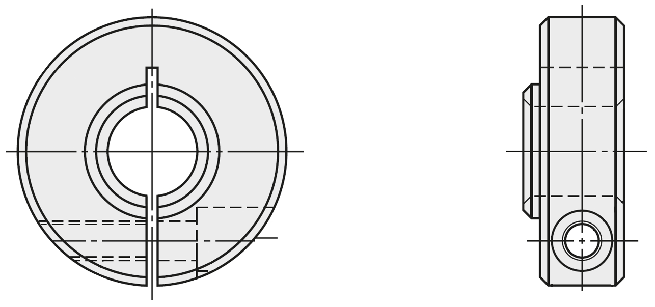
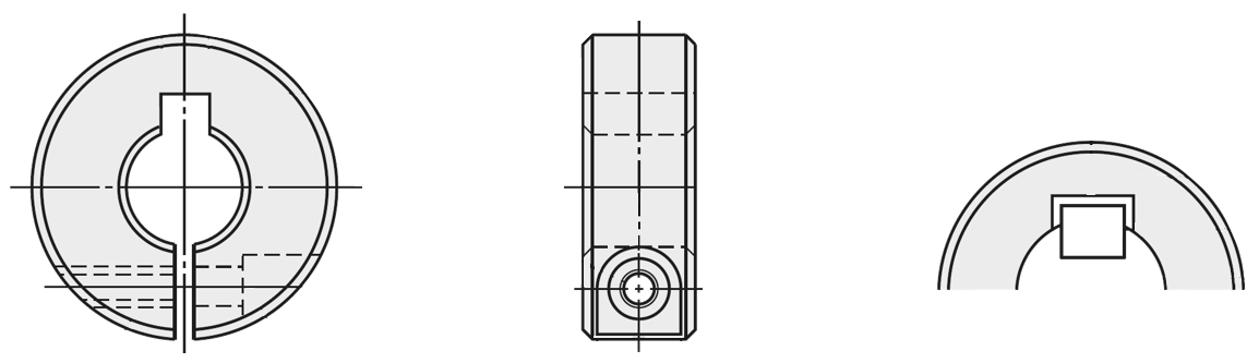
Set collars / stainless steel, steel / slotted / internal thread(Part number list: 2 page)

Part number:
possible part numbers found.Outline drawing and specifications table
Back to the Category Adjusting Rings
Available dimensions and tolerances can be found under the tab More Information .
| Type | Material | Surface Treatment | Accessory | |
| Fine | Coarse | Hex Socket Head Cap Screw 1 pc. | ||
| SCSN | SCSNN | EN 1.1191 Equiv. | Black Oxide Coating | EN 1.7220 Equiv. |
| PSCSN | PSCSNN | Electroless Nickel Plating | EN 1.4301 Equiv. | |
| SSCSN | SSCSNN | EN 1.4301 Equiv. | - | |
Further specifications can be found under the tab More Information .
| Part Number |
| SCCNS20 |
Adjusting Ring Selection Details
- Material: aluminum, plastic, stainless steel, steel
- Coatings: uncoated, burnished, anodized, stove-enameled, LTBC plated, nickel-plated
- Inner diameter: 3 to 100 mm
- External diameter: 7 to 150 mm
- Width: 5 to 36 mm
- Basic shapes: round, chamfered, offset, flattened on one side, flattened on both sides, cross hole
- Shaft fixing: clamping screw, with keyway, slotted clamping, with clamping lever, two-part, with hinge, wedge, quick-release, spring pin, internal thread
Overview of the various designs as PDF
Description/Basics
An adjusting ring is a connecting element that serves as a stopper or a locking device for linear shafts and rotary shafts.
The basic task of the adjusting rings, also called clamping rings, is the fixing by clamping a shaft at a predetermined position. The clamping ring can in this case serve as a stopper or as a positioning jig.
The adjusting ring enables to do without a shoulder on a shaft, as it can be mounted anywhere on a shaft due to the clamping connection. In addition to greater position flexibility, this feature reduces the production costs of the shaft and allows for a greater use of identical parts. Another advantage of the clamping connection of clamping rings is the continuous adjustment of the shaft or its attachments (e.g., ball bearings, timing pulley).
An adjusting ring can be used in applications for linear and rotary movements. For this purpose, MISUMI offers clamping rings in various designs.

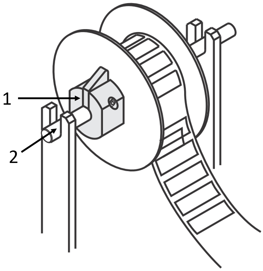
Application example: adjusting ring – (1) rotary shaft, (2) adjusting ring, (3) ball bearings
The appropriate adjusting ring should be selected depending on the application and the loads and forces that occur. MISUMI offers clamping rings in different types of clamping and sizes
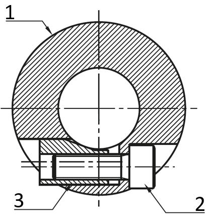
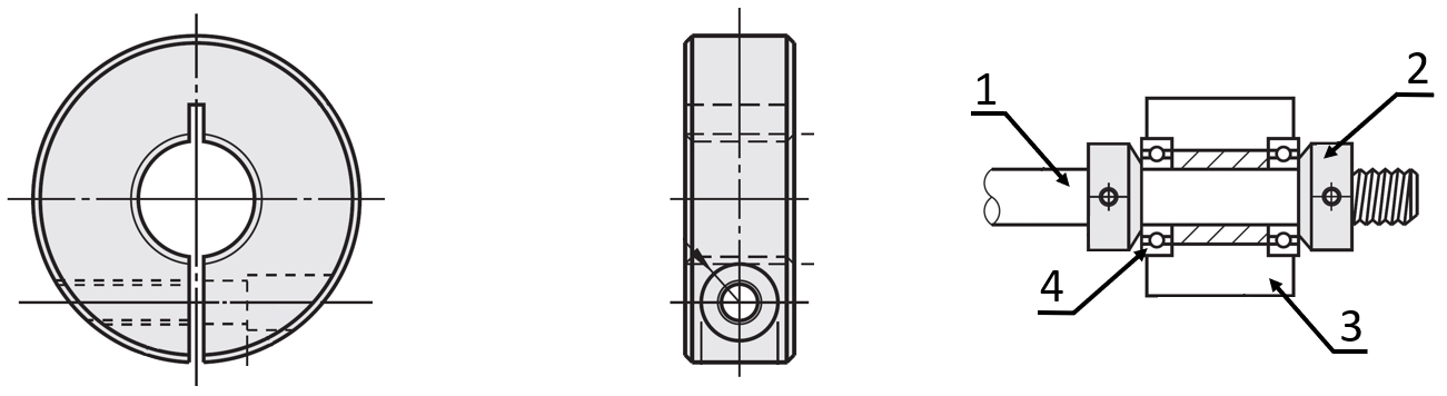
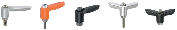
Adjusting ring with set screw
The adjusting ring with set screw is the standard version of adjusting rings. In this variant, the adjusting ring is clamped to the set screw on the shaft.
In order to provide the adjusting ring with a good fit on the shaft with this type of clamping connection, it is often provided with a flat surface. This prevents any damage and deformations to the outer shaft part caused by the clamping pressure of the set screw. Another option to protect the outer part of the shaft is the utilization of a set screw with pins or a pressure piece made of a soft material (e.g., plastic, brass).
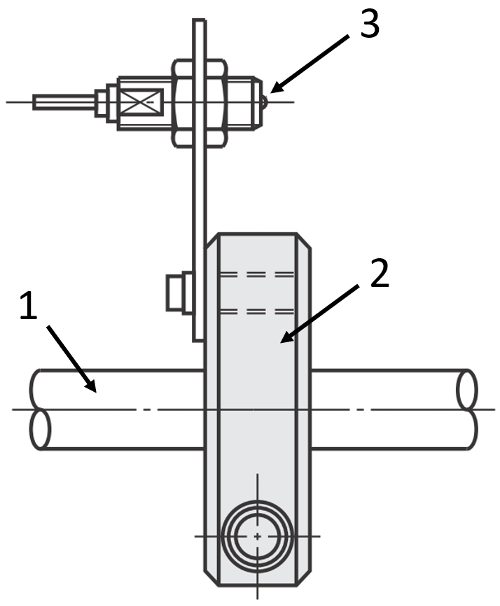
Application example: adjusting ring with set screw and set piece – (1) adjusting ring, (2) set screw, (3) set piece, (4) linear shaft
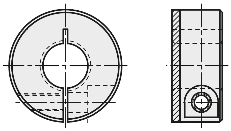
Clamping ring with a slot
The clamping ring with a slot is yet another, very common variant of adjusting rings. Its great advantage is that the clamping of the shaft exists over almost the entire contact surface of the clamping ring. This creates an evenly distributed clamping force, which reduces the risk of deformation or damage to the shaft. Bifurcated clamping rings can also create high clamping forces and ensure a stable fit of the clamping ring on the shaft. Since this type of clamping connection does not require a flat surface on the shaft for the clamping ring, the position of the clamping ring can be freely selected. This allows continuous adjustment on the shaft and the attachments (e.g., ball bearing, timing pulley).
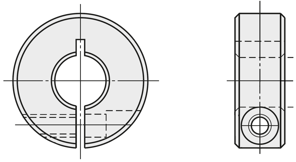
Drawing: clamping ring with slot
Adjusting ring with slot and clamping lever
In applications where adjusting rings must be frequently adjusted, an adjusting ring with clamping lever can be used. This adjusting ring is identical in design to the slotted clamping ring, but it is equipped with a clamping lever that facilitates the fixing and loosening of the adjusting rings. Therefore, there is no additional tool required thanks to the clamping lever on the adjusting ring.
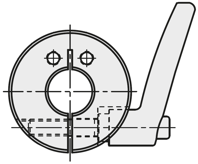
Drawing: clamping ring with clamping lever
Adjusting ring with shoulder (for bearings)
The adjusting ring with shoulder is suitable for clamping ball bearings. The shoulder on the adjusting ring is clamped to the inner ring of the bearing. The adjusting ring with shoulder can thus rotate along the shaft while holding the bearing in the desired position.
Drawing: clamp ring with shoulder
Clamping ring with keyway
Clamping rings with a keyway are a special form of clamping ring as they allow the inclusion of keyways. This special form of adjusting ring enables clamping of timing pulleys or sprockets that are connected to the shaft with a parallel key. If a parallel key protrudes from the assembly part to be clamped, the clamping ring with a parallel key groove can receive the parallel key. This allows the clamping ring to lie flat with the component to be clamped. This makes it possible to maintain the necessary clamping force despite the parallel key.
Drawing: adjusting ring with keyway
Two-part adjusting ring
These adjusting rings, in two-part design, are centrally split adjusting rings that create the clamping force with two screws and are thus mounted on the shaft.
This feature makes it easier to assemble and disassemble these adjusting rings during maintenance, especially in confined spaces, as the shaft does not have to be removed from the shaft holder during maintenance of the adjusting ring.
The split adjusting ring uses the entire contact surface for clamping, as well as the slotted clamping ring, and thus protects the shaft surface.

Drawing: two-part clamping ring
Two-part adjusting ring with slit and hinge
The two-part adjusting ring with hinge is a special variant of the adjusting rings. Like the two-part adjusting ring, this adjusting ring is also divided. However, in this variant, the upper part and lower part of the adjusting ring are connected to each other via a hinge.
This type of clamping facilitates assembly and disassembly of the adjusting ring compared to conventional clamping rings. Another benefit of the two-part adjusting rings with a hinge compared to the conventional two-part clamping rings is the reduced risk of loss during disassembly.
This adjusting ring is suitable for applications where the shaft should not be disassembled. The adjusting ring with hinge is particularly maintenance-friendly and can reduce the maintenance costs of an application.

Drawing: two-part clamping ring with hinge
Clamping ring with wedge
The clamping ring with wedge is a special version of the adjusting rings. This adjusting ring uses an internal wedge for clamping, which presses the adjusting ring onto the shaft when the screw or lever is tightened.
A low tightening torque is necessary for clamping rings with a wedge, as this uses almost the entire contact surface for the clamping. Compared to an adjusting ring with a set screw, no flat surface is necessary and the risk of damage to the shaft is reduced. However, the wedge material should be softer than the shaft material to prevent deformation of the shaft.
Drawing: adjusting ring with wedge – (1) clamping ring, (2) screw, (3) wedge
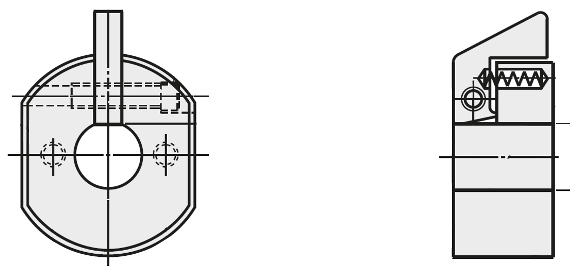
Adjusting ring with quick-release fastener
MISUMI offers adjusting rings with a spring-loaded quick-release fastener for applications that frequently transition or require adjustment. This clamping ring uses spring force to clamp the shaft.
The spring installed in the clamping ring acts on the external operating lever, which is pressed onto the shaft and thus clamps the adjusting ring to the shaft. If the operating lever is actuated, the clamping force drops and the clamping ring can be released, removed or readjusted.
The clamping ring with quick-release fastener is particularly suitable for applications that require changing attachments frequently (e.g., unwinders). Adjusting rings with quick-release fasteners should not be used vertically, as they are not suitable for high axial forces.
Adjusting ring with quick-release fastener
Clamping ring with damper
For applications that require a damped stopper, the MISUMI clamping rings with dampers are an option that can reduce the assembly parts.
The clamping ring with damper is coated with polyurethane rubber, which acts as a damper in the event of an impact and is available in various types of Shore hardness at MISUMI. Therefore, it is not necessary to install a separate impact damper in an application.
Drawing: adjusting ring with damper
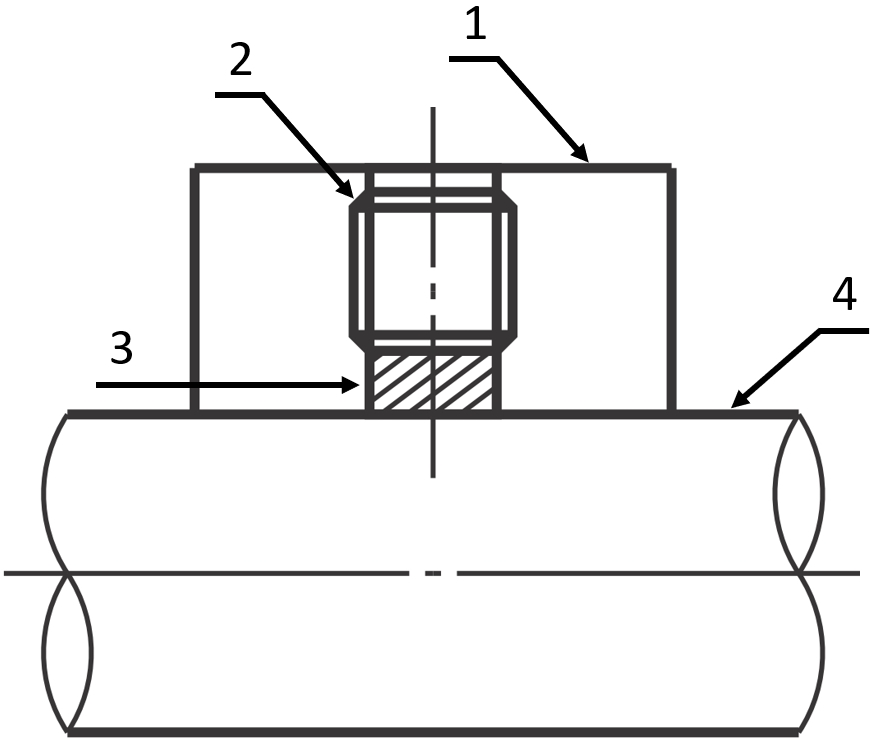
Female threaded adjusting ring
The female threaded adjusting ring is functionally similar to a shaft nut. However, a female threaded adjusting ring is additionally secured by a slotted clamp or a set screw. With this type of clamping function, a locking agent or another locknut is unnecessary with this type of adjusting ring.
The female threaded adjusting ring is available at MISUMI with standard metric threads and fine metric threads.
Drawing: female threaded clamping ring – (1) rotary shaft, (2) female threaded adjusting ring, (3) shaft holder, (4) ball bearings
Areas of Application
An adjusting ring, also called a clamping ring, can be used in many applications in various industries. MISUMI offers clamping rings in various basic forms and clamping types for positioning or as a stopper for various applications.
When using adjusting rings, further complex processing of the shafts can be dispensed with when form-locking clamps are used without the risk of damaging the shaft surface. Likewise, some of our clamp rings do not necessarily allow the shaft to be removed for maintenance, which can reduce maintenance costs.
Materials
MISUMI adjusting rings are made of aluminum, plastic, steel and stainless steel.
Coatings
MISUMI has adjusting rings available as uncoated, bronze-plated, nickel-plated, painted, anodized and LTBC-plated to protect them as much as possible from corrosion.
Dimensions
Round
Chamfered

Flattened on both sides

Flattened on one side

Cross hole
Offset
Installation Information
The maximum axial load of the adjusting rings depends on the clamping force generated. This is created by tightening the set screw, the clamping screw or the clamping lever. Therefore, it is important to maintain the correct tightening torque for the adjusting rings in order to ensure their correct function. The following test values are used for comparison, since the appropriate tightening torque depends on the corresponding application.
General note: The threads of the adjusting rings should be checked for damage after frequent tightening and loosening to ensure the required clamping force.
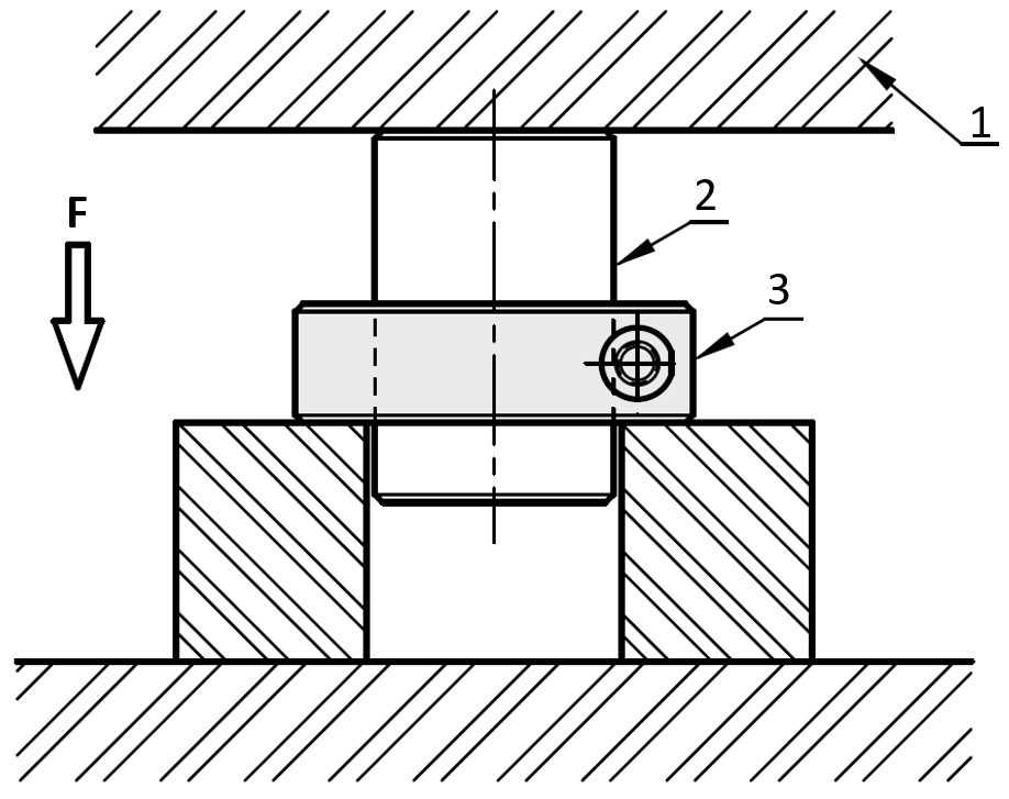
Drawing: test method design for clamping force – (1) test device, (2) linear shaft, (3) adjusting ring
[M] Thread diameter | Tightening torque (Nm) | |
EN 1.1191 equivalent/ | EN AW-2017 equivalent | |
M2.6 | 0.94 | - |
M3 | 1.61 | 1.61 |
M4 | 3.71 | 3.71 |
M5 | 7.54 | 7.54 |
M6 | 12.87 | 7.54 |
M8 | 31.2 | 12.87 |
M10 | 61.75 | 12.87 |
M16 | 267 | - |
Dimensions | Max. axial load (kN) | Weight (g) | |||
[D] Internal diameter | [W] Width | [M] Thread diameter | EN 1.1191 equivalent | EN 1.4301 equivalent | EN 1.1191 equivalent |
6 | *6 | 2.6 | 0,7 | 0,4 | 10 |
8 | 3 | 1,1 | 0,5 | 17 | |
10 | 4 | 1,8 | 1 | 21 | |
8 | *6 | 2.6 | 0,9 | 0,3 | 14 |
8 | 3 | 0,6 | 0,6 | 26 | |
10 | 4 | 2,2 | 1,1 | 32 | |
10 | *6 | 2.6 | 0,7 | 0,3 | 17 |
8 | 3 | 1,2 | 0,4 | 36 | |
10 | 4 | 2 | 1 | 45 | |
12 | 5 | 5,1 | 0,9 | 55 | |
12 | *6 | 2.6 | 0,7 | 0,3 | 16 |
8 | 3 | 1,1 | 0,8 | 34 | |
10 | 4 | 2,8 | 0,8 | 43 | |
12 | 5 | 4 | 1,2 | 52 | |
15 | *8 | 3 | 1,5 | 0,6 | 31 |
10 | 4 | 1,5 | 1,1 | 54 | |
12 | 5 | 5,1 | 1,8 | 69 | |
15 | 6 | 5,6 | 1,4 | 119 | |
16 | *8 | 3 | 2,1 | 1,1 | 29 |
10 | 5 | 7,1 | 2,9 | 55 | |
12 | 5 | 5,4 | 2,3 | 67 | |
15 | 6 | 10,2 | 1,5 | 116 | |
20 | *8 | 3 | 2,2 | 0,8 | 38 |
10 | 5 | 5,8 | 2,7 | 69 | |
12 | 5 | 6,4 | 1,7 | 84 | |
15 | 6 | 10,4 | 3 | 140 | |
25 | *10 | 4 | 3,6 | 1,8 | 66 |
12 | 5 | 8,8 | 2,6 | 98 | |
15 | 6 | 8,8 | 3,6 | 164 | |
30 | *12 | 5 | 8,4 | 2,8 | 111 |
15 | 6 | 8,9 | 2,2 | 185 | |
20 | 8 | 15 | 4 | 318 | |
35 | 15 | 6 | 9,9 | 2,7 | 207 |
40 | 18 | 8 | 21,3 | 6 | 348 |
50 | 22 | 10 | 35,8 | 11,8 | 604 |
Table axial load adjusting rings with slot
*Note: The axial load may differ from the determined data depending on the application. Dimensions marked with * only apply to the SCSJ, SSCSJ versions. All information is provided without guarantee.
[M] Thread diameter | Tightening torque (Nm) | |
EN 1.1191 Equiv. / | EN AW-2017 Equiv. | |
M2.6 | 0.94 | - |
M3 | 1.61 | 1.61 |
M4 | 3.71 | 3.71 |
M5 | 7.54 | 7.54 |
M6 | 12.87 | 7.54 |
M8 | 31.2 | 12.87 |
M10 | 61.75 | 12.87 |
M16 | 267 | - |
Mass | Max. Axial load (kN) | Weight (g) | |||
[D] Internal diameter | [B] Width | [M] Thread diameter | EN 1.1191 | EN 1.4301 Equiv. | EN 1.1191 |
10 | 10 | 4 | 1,6 | 1,2 | 29 |
12 | 10 | 4 | 2,2 | 1,4 | 35 |
15 | 10 | 4 | 1,8 | 1,5 | 37 |
16 | 12 | 5 | 3,0 | 2,3 | 57 |
20 | 12 | 5 | 3,5 | 3,0 | 69 |
25 | 12 | 5 | 3,5 | 3,2 | 88 |
30 | 12 | 5 | 3,2 | 3,2 | 94 |
35 | 15 | 6 | - | 3,1 | 154 |
40 | 15 | 8 | - | 3,1 | 243 |
50 | 15 | 8 | - | 3,1 | 299 |
*Note: The axial load may differ from the determined data depending on the application. All information is provided without guarantee.
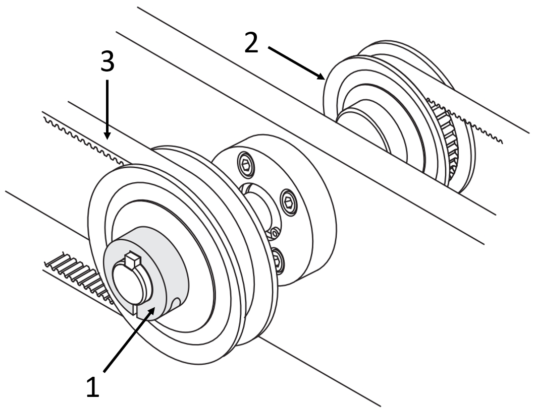
Application example Adjusting rings with keyway for timing pulleys
(1) Adjusting ring with keyway, (2) timing pulley, (3) timing belt
Application example Adjusting ring with shoulder for conveyor belt
(1) Adjusting ring with shoulder, (2) Ball bearing, (3) Flat belt
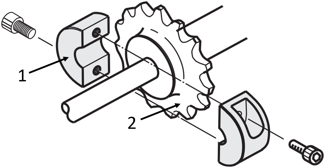
Application example split adjusting ring with chain wheel
(1) Two-piece adjusting ring, (2) Sprocket
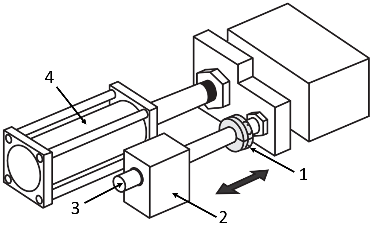
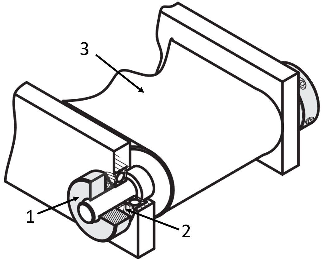
Application example adjusting ring with damper
(1) Adjusting ring with damper, (2) Linear ball bearing block type, (3) Linear shaft, (4) Air cylinder
Application example clamping ring with quick release for unwinder
(1) clamping ring with quick release, (2) Rotary shaft
Application example clamping ring with cross hole for sensor
(1) Linear shaft, (2) clamping ring with cross hole, (3) contact switch


Part number list
| Part number |
|---|
Unit price (excluding VAT)(Unit price including VAT) | Standard shipping days |
|---|
7.10 € ( 8.45 € ) | 5 working days |
9.65 €5.40 € ( 6.43 € ) | Stock item - 1 working dayAvailable for same-day shipping |
6.37 € ( 7.58 € ) | 5 working days |
6.45 € ( 7.68 € ) | 5 working days |
6.94 € ( 8.26 € ) | 5 working days |
8.26 € ( 9.83 € ) | 5 working days |
8.26 € ( 9.83 € ) | 5 working days |
8.54 € ( 10.16 € ) | 5 working days |
8.72 € ( 10.38 € ) | 5 working days |
8.72 € ( 10.38 € ) | 5 working days |
8.72 € ( 10.38 € ) | 5 working days |
8.72 € ( 10.38 € ) | 5 working days |
8.72 € ( 10.38 € ) | 5 working days |
10.17 € ( 12.10 € ) | 5 working days |
10.17 € ( 12.10 € ) | 5 working days |
10.17 € ( 12.10 € ) | 5 working days |
10.17 € ( 12.10 € ) | 5 working days |
13.47 € ( 16.03 € ) | 5 working days |
13.47 € ( 16.03 € ) | 5 working days |
14.43 € ( 17.17 € ) | 5 working days |
14.43 € ( 17.17 € ) | 5 working days |
14.43 € ( 17.17 € ) | 5 working days |
18.99 €10.06 € ( 11.97 € ) | Stock item - 1 working dayAvailable for same-day shipping |
6.37 €3.95 € ( 4.70 € ) | Stock item - 1 working dayAvailable for same-day shipping |
6.45 € ( 7.68 € ) | 5 working days |
6.94 € ( 8.26 € ) | 5 working days |
8.26 € ( 9.83 € ) | 5 working days |
8.26 € ( 9.83 € ) | 5 working days |
8.72 € ( 10.38 € ) | 5 working days |
8.72 € ( 10.38 € ) | 5 working days |
10.17 € ( 12.10 € ) | 5 working days |
13.47 € ( 16.03 € ) | 5 working days |
14.43 € ( 17.17 € ) | 5 working days |
18.99 €8.93 € ( 10.63 € ) | Stock item - 1 working dayAvailable for same-day shipping |
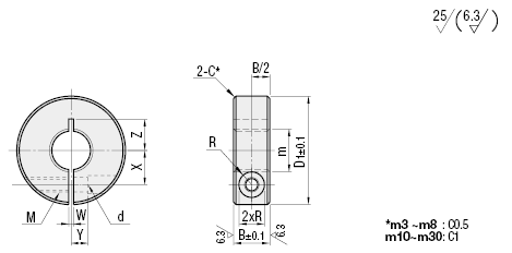
More Information
Basic information
Outline and specifications
Back to the Category Adjusting Rings
| Part Number | B | m×Pitch | D1 | M (Coarse) | d | R | W | X | Y | Z | Unit Price | |||||
| Type | No. | (Fine) | (Coarse) | (Fine) | (Coarse) | SCSN SCSNN | PSCSN PSCSNN | SSCSN SSCSNN | ||||||||
| (Fine Thread Type) SCSN PSCSN SSCSN (Coarse Thread Type) SCSNN PSCSNN SSCSNN | 3 | 8 | M3x0.35 | M3x0.5 | 16 | M3 | 3.4 | 3 | 1.0 | 4.5 | 4.5 | 2.2 | 3~5 | |||
| 4 | M4x0.5 | M4v0.7 | 18 | 5 | 5 | 3 | 3.5~6 | |||||||||
| 5 | M5x0.5 | M5x0.8 | 20 | 5.5 | 5.5 | 4 | 5~6.5 | |||||||||
| 6 | 10 | M6x0.75 | M6x1.0 | M4 | 4.5 | 3.75 | 6 | 6 | 6~6.5 | |||||||
| 8 | M8v0.75 | M8x1.25 | 25 | 1.5 | 8 | 8 | 5 | 8~9 | ||||||||
| *18A | M8x1.0 | - | - | |||||||||||||
| 10 | M10x0.75 | M10x1.5 | 30 | 9 | 9 | 10 | ||||||||||
| *110A | M10x1.0 | - | - | |||||||||||||
| *110B | M10x1.25 | |||||||||||||||
| 12 | M12x1.0 | M12x1.75 | 10 | 10 | 9~10 | |||||||||||
| *112A | M12x1.25 | - | - | |||||||||||||
| *114 | 12 | M14x1.5 | 34 | M5 | 5.5 | 4.5 | 11.5 | 6 | 10~11 | |||||||
| 16 | M16x1.0 | M16x2.0 | 35 | 12 | 12.5 | 11~12 | ||||||||||
| *116A | M16x1.5 | - | 12.5 | - | ||||||||||||
| *118 | M18x1.5 | 40 | 14 | 12~13 | ||||||||||||
| 20 | M20x1.0 | M20v2.5 | 14 | 7 | 13 | |||||||||||
| *120A | M20x1.5 | - | - | |||||||||||||
| *122 | 15 | M22x1.5 | 45 | M6 | 6.6 | 6 | 17 | 14~15 | ||||||||
| 24*2 | - | M24x3.0 | 17 | 16 | ||||||||||||
| *125 | M25x1.5 | - | - | |||||||||||||
| *127 | M27x1.5 | 55 | 20 | 8 | 17~20 | |||||||||||
| 30 | M30x1.5 | M30x3.5 | 20 | 10 | 18~20 | |||||||||||
* 2 marked size in No. is applicable to Coarse Thread Type only.
W dimension of Coarse Thread Type No.5 is 1.5.