- Stock
- Show stock items only
- RoHS Information
- Features, Areas of Application
- [dr] Inner Diameter(mm)
- 3
- 4
- [L] Length (Total)(mm)
- 10
- 12
- Material of Outer Cylinder
- EN 1.4125 Equiv.
- Outer Cylinder Surface Treatment
- No Surface Treatment
- Grease Coating
- Not Provided
- Grease coating
- A Type
- [D] Outer Diameter(mm)
- 7
- 8
- Eccentricity(μm)
- 8
- Basic Rated Load, Dynamic Rating(N)
- 69
- 88
- Ball Material
- Retainer Material
- Seals
- Counterbored Hole
- CAD
- 2D
- 3D
- Est. shipping days
- All
- Same-day shipping possible
- Within 9 working days
- Within 14 working days
Linear ball bearings / flange selectable / stainless steel, steel / treatment selectable / seal selectable

Part number:
possible part numbers found.Outline drawing and specifications table
Dimensional Drawing

Product Specifications
| Counterbored Holes | Type | Outer Cylinder | Balls | Retainer | Operating Ambient Temperature | [A] Accessory | ||||
| Round Flange | Square flange | Compact Flange | [M] Material | [H] Hardness | [S] Surface Treatment | [M] Material | [M] Material | |||
| Opposite Counterbored | LHZR | LHZS | LHZC | EN 1.3505 Equiv. | 58HRC or more | — | EN 1.3505 Equiv. | Plastic (Duracon M90 Equivalent) | −20 to 80°C | Seal [M] Material Nitrile Rubber (-20 to 120°C) |
| Standard | LHFR | LHFS | LHFC | |||||||
| LHFR−N No Seal | LHFS−N No Seal | LHFC−N No Seal | ||||||||
| LHFRF | LHFSF | LHFCF | Stainless Steel (Stainless Steel) | −20 to 110°C | ||||||
| LHFRR | LHFSR | LHFCR | Low Temperature Black Chrome Plating | EN 1.4125 Equiv. | Plastic (Duracon M90 Equivalent) | −20 to 80°C | ||||
| LHFRM | LHFSM | LHFCM | Electroless Nickel Plating | |||||||
| LHFRM−N No Seal | LHFSM−N No Seal | LHFCM−N No Seal | ||||||||
| LHFRMF | LHFSMF | LHFCMF | Stainless Steel (Stainless Steel) | −20 to 110°C | ||||||
| SLHFR | SLHFS | SLHFC | EN 1.4125 Equiv. | 56HRC or more | — | Plastic (Duracon M90 Equivalent) | −20 to 80°C | |||
| SLHFRS | SLHFSS | SLHFCS | Stainless Steel (Stainless Steel) | −20 to 120°C | ||||||
Specification Table
| Part Number | ||
| LHFR8 LHFR−N10  LHFRR8 LHFRR8 LHFRR10L LHFRR10L | (No Seal) (Low Temperature Black Chrome Plating) (L Type Greased) | [ ! ] Alternative grease types available. |
| dr | D Tolerance | L | H | T | d | d1 | t | P.C.D. | W | F | A | Eccentricity (Max.) * 1 | Balls Rows | Perpendicularity * 2 | Basic Load Rating | Mass (g) | |||||||
| Tolerance | Surface Treatment Not Provided | Surface Treatment Provided | Tolerance | C (Dynamic) N | Co (Static) N | Round Flange | Square flange | Compact Flange | |||||||||||||||
| 3 | 0 −0.008 | 7 | 0 −0.011 | 0 −0.015 | 10 | ±0.3 | 19 | 3.5 | 2.5 | 4.5 | 2.1 | 13 | 15 | — | 13 | 0.008 | 4 | 0.008 | 69 | 105 | 7 | 5.1 | 6 |
| 4 | 8 | 12 | 20 | 14 | 16 | — | 14 | 88 | 127 | 8 | 6.2 | 7 | |||||||||||
| 5 | 10 | 15 | 25 | 5 | 3.5 | 6 | 3.1 | 17 | 20 | — | 17 | 167 | 206 | 17 | 13 | 14 | |||||||
| 6 | 0 −0.009 | 12 | 0 −0.013 | 0 −0.018 | 19 | 28 | 20 | 22 | — | 20 | 0.012 | 0.012 | 206 | 265 | 24 | 18 | 21 | ||||||
| 8 | 15 | 24 | 32 | 24 | 25 | — | 24 | 265 | 380 | 37 | 29 | 33 | |||||||||||
| 10 | 19 | 0 −0.016 | 0 −0.021 | 29 | 40 | 6 | 4.5 | 7.5 | 4.1 | 29 | 30 | — | 29 | 372 | 549 | 72 | 52 | 64 | |||||
| 12 | 21 | 30 | 42 | 32 | 32 | — | 32 | 412 | 598 | 76 | 57 | 68 | |||||||||||
| 13 | 23 | 32 | 43 | 33 | 34 | — | 33 | 510 | 784 | 88 | 72 | 81 | |||||||||||
| 16 | 28 | 37 | 48 | 38 | 37 | 22 | 31 | 775 | 1180 | 120 | 104 | 112 | |||||||||||
| 20 | 0 −0.010 | 32 | 0 −0.019 | 0 −0.025 | 42 | 54 | 8 | 5.5 | 9 | 5.1 | 43 | 42 | 24 | 36 | 0.015 | 5 | 0.015 | 882 | 1370 | 180 | 145 | 167 | |
| 25 | 40 | 59 | 62 | 51 | 50 | 32 | 40 | 6 | 980 | 1570 | 340 | 300 | 325 | ||||||||||
| 30 | 45 | 64 | 74 | 10 | 6.6 | 11 | 6.1 | 60 | 58 | 35 | 49 | 1570 | 2740 | 470 | 375 | 388 | |||||||
| 35 | 0 −0.012 | 52 | 0 −0.022 | 0 −0.030 | 70 | 82 | 67 | 64 | 38 | 55 | 0.020 | 0.020 | 1670 | 3140 | 650 | 560 | 575 | ||||||
| 40 | 60 | 80 | 96 | 13 | 9 | 14 | 8.1 | 78 | 75 | 45 | 64 | 2160 | 4020 | 1060 | 880 | 913 | |||||||
| 50 | 80 | 100 | 116 | 98 | 92 | 56 | 80 | 3820 | 7940 | 2200 | 2000 | 2037 | |||||||||||
* 2. Perpendicularity of D to flange mounting surface.
[ ! ] Anti-rust oil is applied at the time of delivery.
[ ! ] No seal supplied for dr = 3 or 4.
[ ! ] There are 2 engraving types for products without seals. Example: Part Number: For LHFR-N10, it will be either LHFR-N10 or LHFR10-N.
By selecting the grease below, change to the product with grease coating is available.
| Type | Product Name | Main Features |
| A Type | Alvania Grease S2 (by Showa Shell Sekiyu) | General-purpose grease suitable for various grease lubrication locations. |
| Y Type | AFF (Made by THK Co., Ltd.) | Grease with less particles, stable rolling resistance, and excellent fretting resistance. |
| G Type | LG2 (Made by NSK Ltd.) | Grease with less particles, excellent wear and rust resistance. |
| L Type | ET-100K (Made by KYODO YUSHI Co., Ltd.) | Superior heat resistance and oxidation stability. Also high adhesion and cohesion with limited splash or leakage. |
| H Type | FGL (Lubriplate) | Suitable for lubrication of equipment used in special hygienic requirements (NSF H-1 Reg. No. 043534) |
| Item | Conditions | Unit | Measurement Method | A Type | Y Type | G Type | L Type | H Type |
| Thickener | — | — | — | Lithium Type | Lithium Type | Lithium Type | Aromatic Diurea | Aluminum Complex Soap |
| Base Oil | — | — | — | Mineral Oil | Fine Synthetic Oil | Mineral Oil + Synthetic Hydrocarbon Oil | Ether Synthetic Oil | USP White Oil |
| Base Oil Kinematic Viscosity | 40°C | mm2/s | JIS K2220 23 | 131 | 100 | 32 | — | 105 (ASTM D-445) |
| 100°C | 12.2 | — | 5.4 | — | 11.5 (ASTM D-445) | |||
| Worked Penetration | — | — | JIS K2220 7 | 283 | 315 | 199 | 280 | 310 (ASTM D-217) |
| Dropping Point | — | °C | JIS K2220 8 | 181 | 220 | 201 | 260 < | 238 (ASTM D-217) |
| Evaporation Amount | 99°C × 22 hr | wt% | JIS K2220 10 | 0.2 | 0.7 | 1.4 | — | 0.27 (ASTM D−972) |
| Oil Separation | 100°C × 24 hr | wt% | JIS K2220 11 | 2.4 | 2.6 | 0.8 | 1.2 | 2.1 (ASTM D−1742) |
| Operating Temp. | In Air | °C | — | -25 to 120 | -40 to 120 | −20 to 70 | −40 to 200 | −12 to 177 |
Selection Supporting Information
Fitting of Shaft O.D. and Bushing I.D.
Fitting of Bushing O.D. and Housing I.D.


| Dimensions (mm) | Linear Bushings Single Type (LMU) I.D. Tolerance | Shaft (SFJ) O.D. Tolerance (g6) | ||||||||
| 0 | ⌀3 to 5 | ⌀6 to 16 | ⌀20 to 30 | ⌀35 to 50 | ||||||
| -0.001 | ||||||||||
| -0.002 | ⌀3 | |||||||||
| -0.003 | ||||||||||
| -0.004 | ⌀4 to 6 | |||||||||
| -0.005 | ⌀8 to 10 | |||||||||
| -0.006 | ⌀12 to 18 | |||||||||
| -0.007 | ⌀20 to 30 | |||||||||
| -0.008 | ||||||||||
| -0.009 | ⌀35 to 50 | |||||||||
| -0.010 | ||||||||||
| -0.011 | ||||||||||
| -0.012 | ||||||||||
| -0.013 | ||||||||||
| -0.014 | ||||||||||
| -0.015 | ||||||||||
| -0.016 | ||||||||||
| -0.017 | ||||||||||
| -0.018 | ||||||||||
| -0.019 | ||||||||||
| -0.020 | ||||||||||
| -0.021 | ||||||||||
| -0.022 | ||||||||||
| -0.023 | ||||||||||
| -0.024 | ||||||||||
| -0.025 | ||||||||||
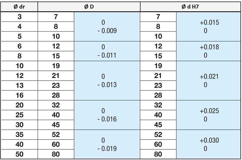
| Product | Customer's design | |||
| I.D. dr | Outer Dia. D | Housing Dia. | ||
| Tolerance | Tolerance H7 | |||
| 3 | 7 | 0 -0.009 | 7 | +0.015 0 |
| 4 | 8 | 8 | ||
| 5 | 10 | 10 | ||
| 6 | 12 | 0 -0.011 | 12 | +0.018 0 |
| 8 | 15 | 15 | ||
| 10 | 19 | 0 -0.013 | 19 | +0.021 0 |
| 12 | 21 | 21 | ||
| 13 | 23 | 23 | ||
| 16 | 28 | 28 | ||
| 20 | 32 | 0 -0.016 | 32 | +0.025 0 |
| 25 | 40 | 40 | ||
| 30 | 45 | 45 | ||
| 35 | 52 | 0 -0.019 | 52 | +0.030 0 |
| 40 | 60 | 60 | ||
| 50 | 80 | 80 | ||
Bushing and Housing will be clearance fit.
Technical Information
■Calculation of Life
- When the linear systems are in motion with loads, rolling surfaces and races are subject to repeated stress and will show stress-induced scaly damages called "flaking". The total run distance of a linear system until this flaking first appears is the life of a linear system.
Rated life can be calculated using the formula below from the basic dynamic load rating and the actual load applied to the linear bushings.
C: Basic Dynamic Load Rating (N)
P: Applied Load (N)
fw: Load Factor (Refer to Table-4)
fH : Hardness Factor (Refer to Fig.-1)
fT : Temperature Factor (Refer to Fig.-2)
fC : Contact Factor (Refer to Table-3)
If the ample hardness of the shafts are not obtained, the allowable loads are reduced and the life will be shortened.


| Number of bushings on one shaft | Contact Factor fc |
|---|---|
| 1 | 1.00 |
| 2 | 0.81 |
| 3 | 0.72 |
| 4 | 0.66 |
| 5 | 0.61 |
| Conditions of Use | fw |
|---|---|
| No external shocks or vibrations when running in low speed: 15 m/min. or less | 1.0 to 1.5 |
| No excessive external shocks or vibrations when running in medium speed: 60 m/min. or less | 1.5 to 2.0 |
| External shocks and vibrations given when running in high speed: 60 m/min. or more | 2.0 to 3.5 |
Life in hours can be obtained by calculating travel distance per hour.
If the stroke length and number of strokes are constant, life in hours can be calculated using the following formula.
n1: Reciprocating Cycles per Minute (cpm)
Cautions/Prohibitions
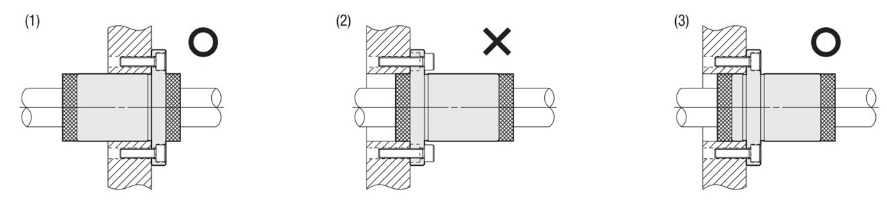
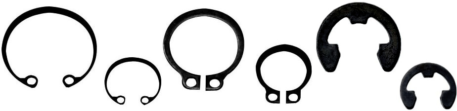
(1) When mounting Linear Bushings and Housings, use Retaining Rings (Snap Rings), Stoppers, etc.

(2) Linear Bushings are not suitable for rotating motion or usage with repetitive insertion and extraction of shafts. Forced use may cause damage.

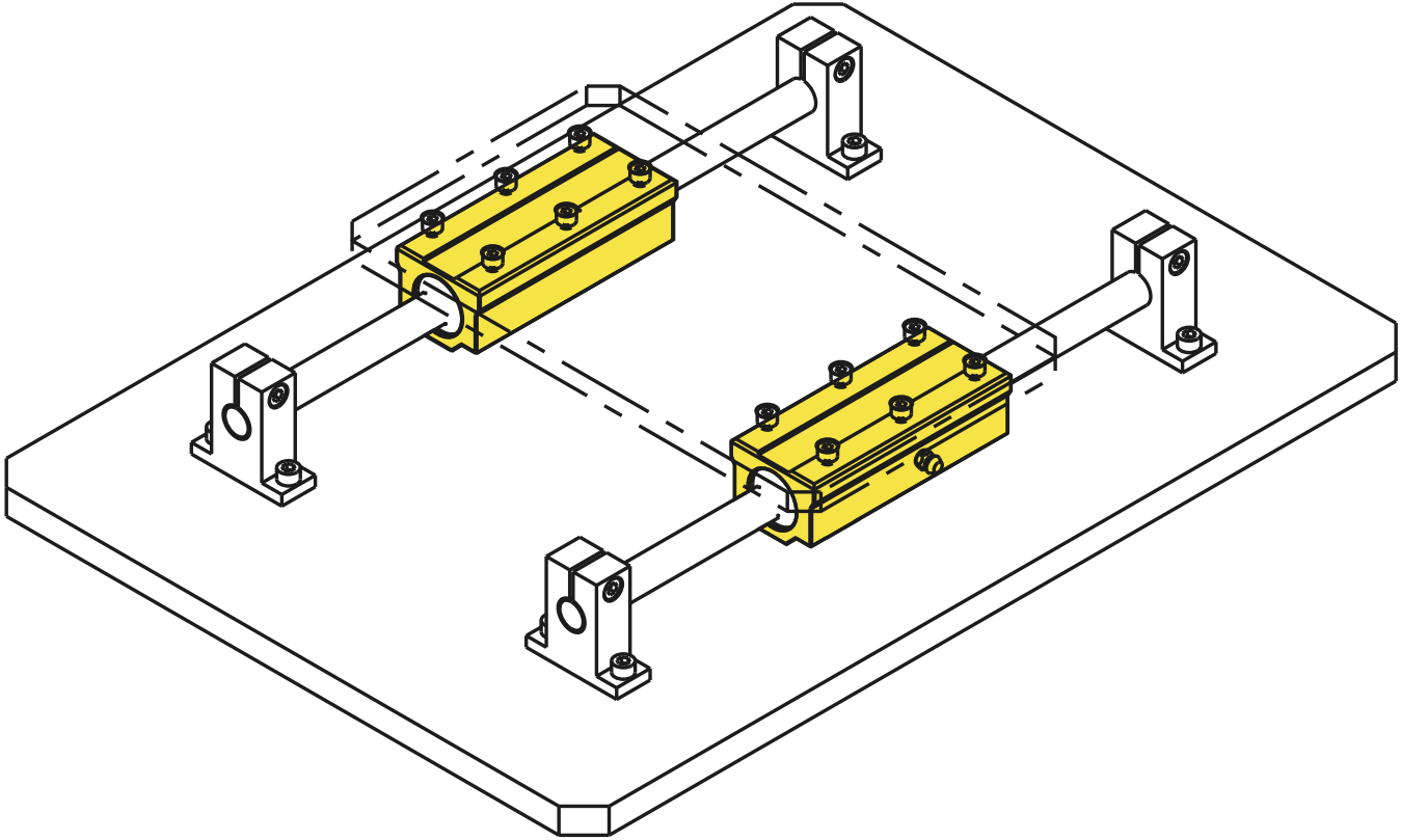
(3) If large moment load (offset load) is to be applied, Short/Single Type Linear Bushings are not suitable. Use of Double Type or Multiple Linear Bushings is recommended.

(4) When assembling with linear shafts, forcing the shaft into the bushing with angular misalignment may cause the ball retainers to deform and balls to fall out. Be sure to align the centers and insert the shaft gently.

Linear Ball Bushing Selection Details
- Inner diameter [dr]: 3 mm – 100 mm
- Total length [L]: 10 mm – 300 mm
- Housing material: aluminum, stainless steel (stainless steel), steel
- Ball material: stainless steel (stainless steel), steel
- Ball cage material: plastic, stainless steel (stainless steel)
- Surface treatment: without, chemically nickel-plated, LTBC
- Radial offset (μm): 50 μm – 4 μm
At MISUMI, you will find the following linear bearing versions: with locking ring with groove, with dust seal, with lubrication unit (MX), with grease nipple, housing open at the bottom/open, with clearance compensation, with flange, with centred flange, with round flange, with flattened round flange (compact flange), with square flange, with block housing, with wide barrel and ball housing, ball cage guides for linear and rotational movements (limited stroke).
Description/Basics
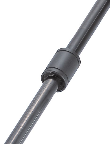
Linear ball bushings convert the rolling motion of steel balls (4) into infinite linear motion. They can implement highly precise and low-friction linear motion and can be used in almost all industries, e.g., in systems for semiconductor parts, electronic components and in food packaging.
Ball recirculating bushings are used in conjunction with linear shafts. The linear movement mechanism uses steel balls (4) for unlimited linear movement.
Linear bearing units allow linear shafts to travel indefinitely through steel balls that are constantly circulating within the running grooves directed by the outer cylinder and ball cage (3).
Compared to plain bearings, ball bushings perform linear movements with lower friction and high accuracy. They are used in many applications, such as conveyors and semiconductor manufacturing facilities.
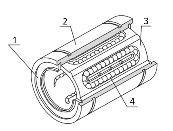
Linear Bearing Unit Design - (1) Dust Seal, (2) Outer Cylinder, (3) Ball Cage, (4) Steel Balls
Dynamic friction coefficient in comparison
| Design | Dynamic friction coefficient (μ) | |
| Miniature profile rail guide | 0.004 ~ 0.006 | |
| Profile rail guide for medium and heavy loads | 0.002 ~ 0.003 | |
| Cross roller guides | 0.001 ~ 0.003 | |
| Cross roller tables | 0.001 ~ 0.003 | |
| Linear ball bearing | 0.002 ~ 0.003 | |
| Ball cage guides | 0.0006 ~ 0.0012 | |
The specified values are for comparison purposes only and are therefore not reference values.
Areas of Application
Linear ball bushings have a linear working direction and can be used for horizontal or vertical linear movements. Therefore, MISUMI linear ball bushings can be used in almost all industries. Since linear ball bushings are intended only for axial movement, rotational use would lead to premature fatigue or destruction of the ball bushings. For rotary movements, we therefore recommend ball cage guides, which enable not only infinite linear movements (stroke-limited) in addition to infinite rotary movements.
Common applications are lifting mechanisms or guides for cylinders. The ball bushings are also a good variant for additional guide. In addition, these linear ball bushings are often found in 3D printers, metering systems, measuring devices, positioning and alignment devices, bending devices and sorting systems.
For systems with increased particle development (e.g., dust and other abrasive particles), the linear systems should be protected with covers or bellows. The ingress of particles leads to a clumping of the lubricating grease or to significantly increased abrasion. By clumping the grease, the balls block in the ball circulation, which results in unscheduled maintenance.
Materials
Linear ball bearings consist of different materials due to their design and the individual components. MISUMI uses high-quality materials to achieve the longest possible service life. The following materials are available:
- External cylinder: stainless steel (stainless steel) ~56HRC, steel with ~58HRC
- Ball: stainless steel (stainless steel), steel
- Ball cage: plastic, stainless steel (stainless steel)
- Housing: aluminum, stainless steel (stainless steel), steel
- Seal: nitrile rubber
You can find more detailed material information in the tab Technical Drawing.
Coatings
To protect linear ball bushings from corrosion, the surface can be chemically nickel-plated.
As an alternative to a chemical nickel-plating, ball bushings can also be coated with LTBC. The LTBC coating (Low Temperature Black Chrome Platinum) is a surface treatment that protects against corrosion and has low reflection. The coating consists of a 5 μm thick chrome ceramic layer with fluoropolymer infusion and it deposits as a black film. In addition, the LTBC coating is crack-proof and interchangeable and is therefore resistant to delamination due to extreme or repeated bending. LTBC-coated linear ball bearings are thus particularly suitable for locations where corrosion or light reflections are undesirable.
Note: the inner wall of LTBC coated linear bushing units is not surface treated.
LTBC-coated linear ball bushing - state after 50 km glide test under 412N load.
Comparison test of corrosion protection
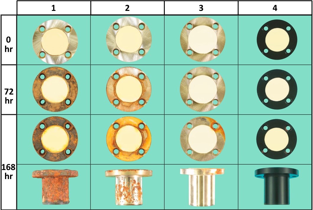
Salt water spray test according to JIS H8502. Test piece: simple flanged linear ball bushing
(1) EN 1.3505 equiv., (2) EN 1.4125 equiv., (3) chemically nickel-plated, (4) LTBC coating, (hr = duration in hours)
Instructions for use
- MISUMI linear bearings should be used in conjunction with MISUMI linear shafts.
- We recommend using a hardened linear shaft in the g6 tolerance.
- An additional hard chrome plating of the linear shaft makes it more wear-resistant.
- When installing ball bushings in housings, we recommend an H7 housing tolerance. Too close a tolerance will reduce the internal contact travel [dr] to the shaft and can lead to increased wear and premature failure.
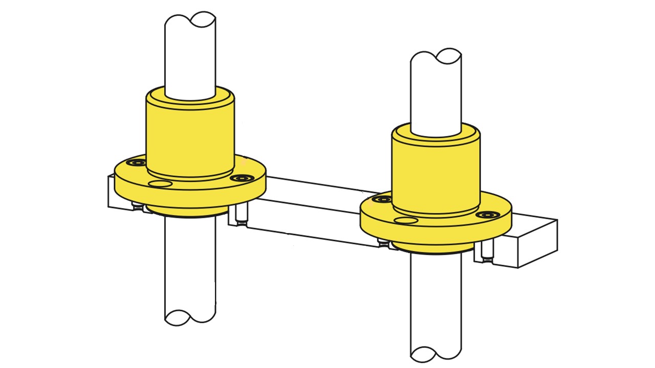
- The utilisation of two ball bushings on a steel shaft improves the shaft guide in a system. However, if the angular errors are too high, a self-aligning linear ball bushing should be selected.
- When utilising two linear shafts, the drive should be centred in the system to avoid unnecessary stresses/lever effects.
- The service life, also called nominal service life, should be calculated using the present load case. Here you can perform your service life calculation.
- Depending on local conditions such as temperature, humidity and gases, a variant made of stainless steel or an LTBC coating is recommended.
- When the linear shafts bend sharply, a self-aligning/self-adjusting linear ball bushing should be selected.
Installation Information
General installation instructions for linear ball bushings and linear shafts
MISUMI linear ball bushings should be used in conjunction with MISUMI linear shafts (hardened, tolerance g6).
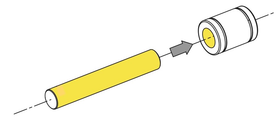
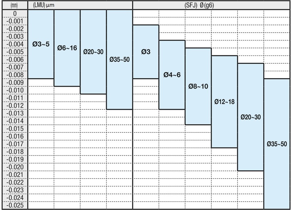
MISUMI tolerance range: inner diameter linear ball bushings (LMU) and outer diameter linear shafts (SFJ).
General installation instructions for linear ball bushings and housings
MISUMI linear ball bushings should be used in conjunction with MISUMI housings (tolerance H7).
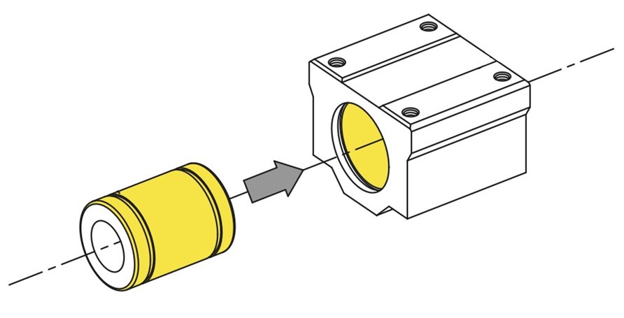
MISUMI tolerance range: outer diameter of linear ball bushing and inner diameter of housing.
Standard linear ball bushing installation instructions
1. When installing standard linear ball bushings, you can use the following locking means: retaining rings (clamping rings), stoppers
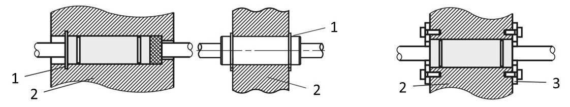
(1) retaining rings, (2) housing, (3) stopper/LMST fixing plate
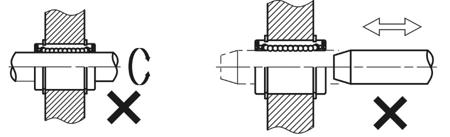
2. Ball bushings are not suitable for rotary motion and applications requiring repetitive insertion and removal of linear shafts. Such a misuse of the linear ball bushing could damage the recirculating ball bushing.
3. Simple linear ball bushings are not suitable for large torque loads (offset load/lever effect). The use of double or multiple linear bushings is recommended for these load cases.
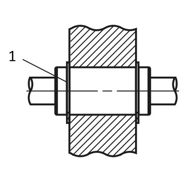
(1) Linear ball bushing with two grooves
4. When assembling linear shafts, forceful slanted insertion into the linear ball bushing can cause the ball cage to bend and the balls to fall out. Be sure to centre the steel shaft to the linear ball bushing before inserting the steel shaft into the linear ball bushing.
Installation instructions for linear ball bushings with stopper/fixing plate
Through the stopper plates, the versions can be designed independently of the housing length.
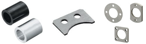
(1) Attachment, (2) linear ball bushing – standard, (3) linear shaft, (4) LMST fixing plate
The stopper plates enable the ball sleeve and linear shaft to be installed flush against the end faces.
(1) Linear shaft, (2) housing, (3) linear ball bushing – standard, (4) spacer sleeve LBS/LBSA for linear ball bushings, (5) LMST fixing plate
The LMST fixing plates can also be used to lock linear bushings in place.
(2) housing, (4) LMST fixing plate
Assembly Instructions for Linear Ball Bushings with Flange and Lubrication Unit MX
When fastening the linear ball bushing with the lubrication unit MX, do not insert the housing of the lubrication unit as guide as shown in (2), as this can damage the housing. Instead, use the flange and guide version as shown in (3).
Do not disassemble the linear ball bushing with flange and lubrication unit MX, as this will impair function.
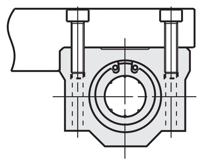
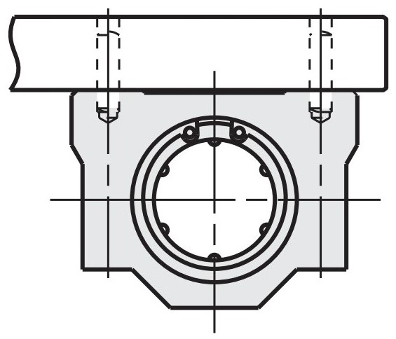
Assembly Instructions for Linear Ball Bushings with Housing and without Cylinder Pin Hole
During interface assembly, centring on the lateral reference surface can be eliminated by means of the cylinder pin holes.
This reduces the machining effort of the upper plate to be mounted on the block.
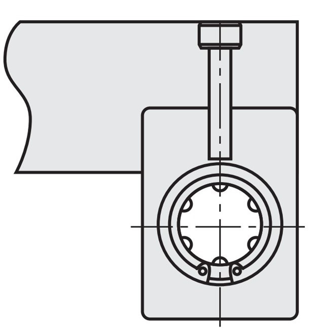
Positioning with plate end cover

Positioning with cylinder pins
Positioning with plate end cover
Positioning with cylinder pins
General Maintenance Instructions
Grease the rows of balls inside the ball bushing before use. Then grease regularly during use. Grease reduces friction by forming a layer between the balls and rolling shaft surfaces and prevents seizing. Loss of grease and degradation of grease shorten the service life of linear guides.
- Recommended grease: lithium soap grease
- Recommended lubrication interval: every 6 months
*Every 3 months for extended work or every 1000 km. Maintenance intervals vary depending on the application and ambient conditions.
Lubrication
Linear ball bushings from MISUMI are delivered coated with a corrosion protection oil. Exceptions to this are the designs with lubrication unit MX. After removing the anti-corrosion oil, we recommend lubricating the bearings.
If you select one of the following lubricants in the configurator, you can order pre-lubricated versions. The versions L, G and H are prefilled with grease, whereby L and G offer a strong reduction in particle formation by means of a suitable grease distribution during operation (see quantitative comparison of particle formation below). Lubrication units MX are filled with lithium soap grease.


Assembly of the lubrication unit MX
The lubrication unit MX is equipped with a fibre insert with lubricant. The capillary effect allows the lubricant to be properly applied to contact surfaces. For this purpose, a constant oil film is formed between balls and steel shaft, which significantly prolongs the lubrication intervals.
_cleaned_numbering.jpg)
Recirculation ball bushing with lubrication unit - (1) MX Lubrication Unit, (2) MX Lubrication Unit - Plastic Housing, (3) Lubricant Pads, (4) Dust Seal, (5) Balls, (6) Linear Shaft
Properties of the MX lubrication unit
Longer maintenance intervals: the long-lasting lubricant performance leads to a significant reduction in maintenance, especially in machine and equipment environments where lubrication is difficult to achieve.
Environment: the MX lubrication unit helps reduce lubricant consumption and thus protects the environment.
Cost benefit: it contributes to reducing maintenance costs and failure rate caused by failing to lubricate.
Less effort: it is not necessary to refill the lubricant prior to use, since the ball parts are already filled with a lithium soap-based grease in addition to the lubrication unit.
Comparison test of linear ball bearings and linear ball bearings with lubrication unit
Test conditions:
- Sample: linear ball bushing LMU12 with rust protection oil and linear ball bushing with lubrication unit LMU-MX12
- Effective load: 206N (50% of the dynamic load rating of 412N)
- Average speed: 42 m/min (0.7 m/s)
- Stroke: 100 m
- Lubricant: lubricating grease, only initial filling (only LMU-MX12)
- Shaft material: EN 1.3505 Equiv. (58HRC)
- Duration: 24-hour continuous operation
*The above test conditions serve only as reference values and cannot be considered as a manufacturer warranty.
Test result:
With an effective test load of 50% of the load-carrying capacity of 412N, the design with the MX lubrication unit could achieve a continuous output of 2.5-fold longer than with no MX lubrication unit.
*Since the 2007 catalogue, the data have been updated after the safety limit has been confirmed by further data from test results.
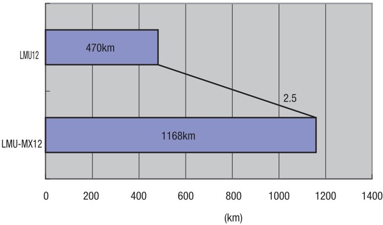
Endurance test result - standard linear ball bearing LMU, linear ball bearing LMU-MX with lubricant unit
_M0101000000.jpg)
_M0103000000_.jpg)
Accessories for Linear Ball Bearing
_M0102000000_.jpg)


Part number list
| Part number |
|---|
Unit price (excluding VAT)(Unit price including VAT) | Standard shipping days |
|---|
21.41 € ( 25.48 € ) | 14 working days |
26.36 € ( 31.37 € ) | 9 working days |
20.61 € ( 24.53 € ) | Stock item: 1 working dayAvailable for same-day shipping |
22.84 € ( 27.18 € ) | 9 working days |
34.29 € ( 40.81 € ) | 9 working days |
18.67 € ( 22.22 € ) | 14 working days |
23.48 € ( 27.94 € ) | 9 working days |
17.88 €8.58 € ( 10.21 € ) | Stock item: 1 working dayAvailable for same-day shipping |
20.41 € ( 24.29 € ) | 9 working days |
31.55 € ( 37.54 € ) | 9 working days |
21.74 €11.96 € ( 14.23 € ) | Stock item: 1 working dayAvailable for same-day shipping |
27.16 € ( 32.32 € ) | 9 working days |
20.95 €10.68 € ( 12.71 € ) | Stock item: 1 working dayAvailable for same-day shipping |
23.56 € ( 28.04 € ) | 9 working days |
34.62 € ( 41.20 € ) | 9 working days |