Configure
- Stroke(mm)
- 50
- 100
- 150
- 200
- 250
- 300
- 350
- 400
- Max. Transportable Mass Range (Horizontal)(kg)
- Max. Transportable Mass (Horizontal)(kg)
- 2
- 4
- 6
- Max. Transportable Mass Range (Vertical)(kg)
- Max. Transportable Mass (Vertical)(kg)
- 1
- 2
- 4
- Lead(mm)
- 2
- 6
- 12
- Brake
- Max. Thrust Force Range(N)
- Max. Push Force(N)
- 45
- 90
- 150
- Environmental Spec.
- Maximum Velocity(mm/sec)
- 100
- 300
- 600
- Controller Type
- Motor Mounting Direction
- Cable Length(m)
- 1
- 3
- 5
- 10
- CAD
- 2D
- 3D
- Est. shipping days
- All
- Within 14 working days
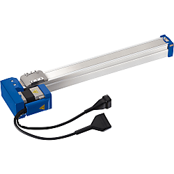
Single Axis Robots RS1 / Motor Wrap


Part number:
possible part numbers found.Outline drawing and specifications table
[Notes on Usage With Windows 11]
A "dedicated driver" is required to use the Support Software "RS-Manager."
*1. For Windows 8 to 11, you must disable "Force Driver Signature" when installing the driver.
*2. The RS-Manager for Windows 11 will be available with shipments after October 2023. (Compatible with Ver. 1.4.5 or later)
![[High Accuracy]Z-Axis Dovetail Slide, Rack & Pinion / Rectangle / Dimensional Drawing](http://uk.misumi-ec.com/linked/item/10302583820/img/drw_01_001.gif)
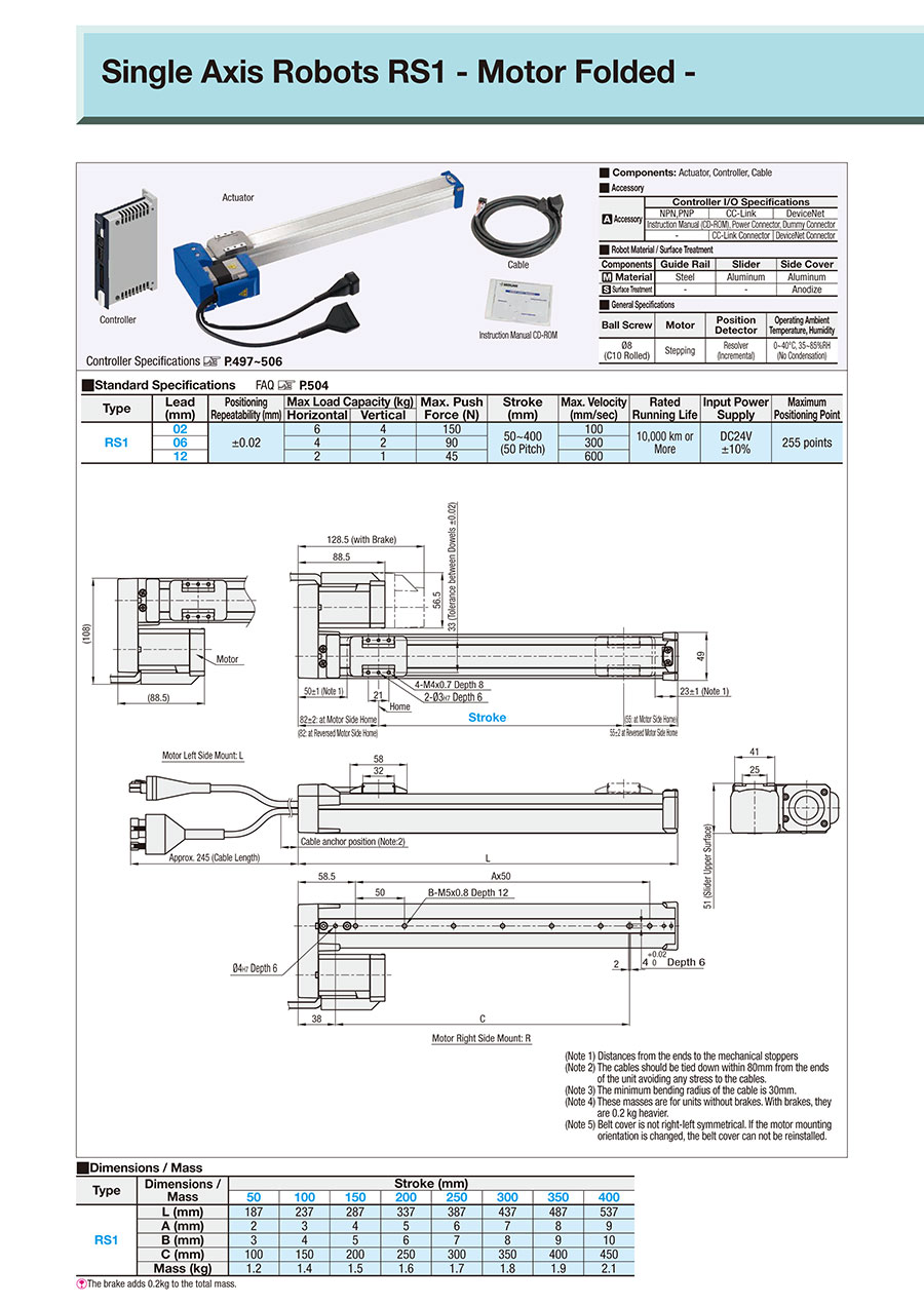
(*1) Distances from the ends to the mechanical stoppers
(*2) The cables should be tied down within 80 mm from the ends of the unit to avoid any stress to the cables.
(*3) The minimum bending radius of the cable is 30 mm.
(*4) These masses are for units without brakes. The brake adds 0.2 kg to the mass.
(*5) Belt cover is left-right asymmetric. If the motor mounting orientation is changed, the belt cover cannot be reinstalled.
Motor Left Side Mount: L
Motor Right Side Mount: R
[!]I/O Cable is not included. When purchasing, please specify alterations (T/TP).
■Robot Material / Surface Treatment
| Components | Guide Rail | Slider | Side Cover |
| [M] Material | Steel | Aluminum | Aluminum |
| [S] Surface Treatment | — | — | Anodize |
■Components: Actuator, Controller, Cable
■ Accessory
■ Accessory
| [A] Accessories | Controller I/O Specifications | ||
| NPN, PNP | CC-Link | DeviceNet | |
| Instruction Manual (CD-ROM), Power Connector, Dummy Connector | |||
| — | CC-Link Connector | DeviceNet Connector | |
Specification Table
| Part Number | — | Motor Mounting Orientation | — | Controller | — | I/O Module | — | Cable Length | — | Stroke | |
| RS102B | — | L | — | C1 | — | N | — | 3 | — | 400 | |
| RS102B | — | L | — | P1 | — | 3 | — | 400 | (Controller: P1) |
■ General Specifications
■ Basic Specifications
[ ! ] If you select a model with a brake, the Max. Load Capacity (kg) will apply when in the vertical position.
| Ball Screw | Motor | Position Detector | Service Ambient Temperature /Humidity |
| ⌀8 (C10 Rolled) | Stepping | Resolver (Incremental) | 0 to 40°C ·35 to 85%RH (No Condensation) |
| Type | Lead (mm) | Positioning Repeatability (mm) | Max. Load Capacity (kg) | Max. Push Force (N) | Stroke (mm) | Max. Velocity (mm/sec) | Rated Running Life | Controller Input Power Supply | Maximum Positioning Point | |
| Horizontal | Vertical | |||||||||
| RS1 | 02 | ±0.02 | 6 | 4 | 150 | 50 to 400 (50 Pitch) | 100 | 10,000 km or More | 24 V DC ±10% | 255 points |
| 06 | 4 | 2 | 90 | 300 | ||||||
| 12 | 2 | 1 | 45 | 600 | ||||||
■Dimensions / Mass
[ ! ]The brake adds 0.2 kg to the mass.
([!]1) Choose "with Brake" type for use in vertical applications. ([!]2) When the pulse train type controller is selected, the I/O type selection is not required.
| Type | Dimensions / Mass | Stroke (mm) | |||||||
| 50 | 100 | 150 | 200 | 250 | 300 | 350 | 400 | ||
| RS1 | L (mm) | 187 | 237 | 287 | 337 | 387 | 437 | 487 | 537 |
| A (mm) | 2 | 3 | 4 | 5 | 6 | 7 | 8 | 9 | |
| B (mm) | 3 | 4 | 5 | 6 | 7 | 8 | 9 | 10 | |
| C (mm) | 100 | 150 | 200 | 250 | 300 | 350 | 400 | 450 | |
| Mass (kg) | 1.2 | 1.4 | 1.5 | 1.6 | 1.7 | 1.8 | 1.9 | 2.1 | |
| Part Number | Selection | ||||||
| Type | Lead (mm) | With or w/o Brake (" ! "1) | Motor Mounting Orientation | Controller (" ! "2) | I/O Module | Cable Length (m) | Stroke (mm) |
| RS1 | 02 | None: Blank Provided: B | Right Side Mount: R Left Side Mount: L | Point Control: C1 Pulse Control: P1 (24 V DC ±10%) | NPN: N PNP: P CC-Link: C DeviceNet: D | 1 3 5 10 (Flexible Cable) | 50 to 400 (50 mm Increments) |
| 06 | |||||||
| 12 | |||||||
Alterations
 | Part Number | — | Motor Mounting Orientation | — | Controller Type | — | I/O Type | — | Cable Length | — | Stroke | — | (G, E, etc.) | ||
| RS102B | — | L | — | C1 | — | N | — | 3 | — | 400 | — | G - E | |||
| Alterations | Grease Type Alteration | Handset Terminal Standard Specification | Handset Terminal w/ Deadman's Switch Specification | Support Software w/ USB Communication Cable | Support Software w/ D-Sub Communication Cable | I/O Cable | Cable for Daisy Chain Connection | Instruction Manual MJ5: Body KJ3: Controller (C1) KJ4: Controller (P1) | Main Body Plastic Color Alteration | |
Change of Home Position |   |  |  |  |  |  |  | |||
| Communication Specifications: RS232C | Communication Specifications: RS232C | T: Controller C1 TP: Controller P1 | Length: 300 mm | |||||||
| Code | G | E | H | D | S | R | T/TP | C | MJ5/KJ3/KJ4 | BC |
| Spec. | Change grease to Low Dust Generation Grease. (NSK LG2) | Change Home Position to Reverse Motor Side. | Handset Terminal Standard Specification is included. | Handset Terminal w/ Deadman's Switch is included. | Support Software w/ USB Communication Cable is included. | Support Software w/ D-Sub Communication cable is included. | I/O Cable is included. Required for NPN/PNP configurations. | A cable to connect multiple controllers. Up to 16 controllers can be connected. | Instruction Manual | Change the actuator plastic color to black. |
[ ! ]I/O Cable is required for Parallel Communication I/O Control.
[ ! ]Please select the correct I/O cable type for the appropriate controller type.
[Instruction Manual (booklet version)]
| Japanese | English | Chinese | |
| For Actuator | MJ5 | ME5 | MC5 |
| For Controller (C1) | KJ3 | KE3 | KC3 |
| For Controller (P1) | KJ4 | KE4 | KC4 |
Part number list
Number of items
| Part number |
|---|
Unit price (excluding VAT)(Unit price including VAT) | Standard shipping days |
|---|
- ( - ) | 14 working days |
- ( - ) | 14 working days |
- ( - ) | 14 working days |
- ( - ) | 14 working days |
- ( - ) | 14 working days |
- ( - ) | 14 working days |
- ( - ) | 14 working days |
- ( - ) | 14 working days |
- ( - ) | 14 working days |
- ( - ) | 14 working days |
- ( - ) | 14 working days |
- ( - ) | 14 working days |
- ( - ) | 14 working days |
- ( - ) | 14 working days |
- ( - ) | 14 working days |
- ( - ) | 14 working days |
- ( - ) | 14 working days |
- ( - ) | 14 working days |
- ( - ) | 14 working days |
- ( - ) | 14 working days |
- ( - ) | 14 working days |
- ( - ) | 14 working days |
- ( - ) | 14 working days |
- ( - ) | 14 working days |
- ( - ) | 14 working days |
- ( - ) | 14 working days |
- ( - ) | 14 working days |
- ( - ) | 14 working days |
- ( - ) | 14 working days |
- ( - ) | 14 working days |
- ( - ) | 14 working days |
- ( - ) | 14 working days |
- ( - ) | 14 working days |
- ( - ) | 14 working days |
- ( - ) | 14 working days |
- ( - ) | 14 working days |
- ( - ) | 14 working days |
- ( - ) | 14 working days |
- ( - ) | 14 working days |
- ( - ) | 14 working days |
- ( - ) | 14 working days |
- ( - ) | 14 working days |
- ( - ) | 14 working days |
- ( - ) | 14 working days |
- ( - ) | 14 working days |
- ( - ) | 14 working days |
- ( - ) | 14 working days |
- ( - ) | 14 working days |
- ( - ) | 14 working days |
- ( - ) | 14 working days |
- ( - ) | 14 working days |
- ( - ) | 14 working days |
- ( - ) | 14 working days |
- ( - ) | 14 working days |
- ( - ) | 14 working days |
- ( - ) | 14 working days |
- ( - ) | 14 working days |
- ( - ) | 14 working days |
- ( - ) | 14 working days |
- ( - ) | 14 working days |
More Information
Basic information
Outline and specifications
Specifications/Overview
 Note
NotePower shutdown circuit is not provided in this controller in order to provide maximum flexibility for customer-specific safety scheme.
Please be sure to provide an external power shutdown circuit and form an emergency stop circuit.
| ■Allowable Overhang Load | ■Allowable Static Moment | ||||||||||||||||||||||||||
| ·Horizontal Use | ·Wall Mounting Use | ·Vertical Use | ·Moment Diagram | ||||||||||||||||||||||||
 |  |  |  | N⋅m | |||||||||||||||||||||||
| MY | MP | MR | |||||||||||||||||||||||||
| 16 | 19 | 17 | |||||||||||||||||||||||||
| mm | mm | mm | ■Max. Velocity (mm/sec) | ||||||||||||||||||||||||
| Lead | Mass | A | B | C | Lead | Mass | A | B | C | Lead | Mass | A | C | Type | Lead (mm) | Stroke (mm) | |||||||||||
| 02 | 6 kg | 863 | 40 | 60 | 02 | 6 kg | 39 | 26 | 789 | 02 | 4 kg | 53 | 53 | 50 | 100 | 150 | 200 | 250 | 300 | 350 | 400 | ||||||
| 4 kg | 869 | 61 | 92 | 4 kg | 72 | 48 | 829 | 2 kg | 118 | 118 | RS1 | 02 | 100 | ||||||||||||||
| 06 | 4 kg | 567 | 56 | 84 | 06 | 4 kg | 63 | 43 | 507 | 06 | 2 kg | 107 | 107 | 06 | 300 | ||||||||||||
| 3 kg | 556 | 76 | 112 | 3 kg | 92 | 62 | 516 | 1 kg | 223 | 223 | 12 | 400 to 600 | |||||||||||||||
| 2 kg | 687 | 116 | 169 | 2 kg | 149 | 102 | 656 | 12 | 1 kg | 204 | 204 | [!]Please confirm the details of the Max. Speeds based on various strokes with MISUMI web Simulator. | |||||||||||||||
| 12 | 2 kg | 667 | 107 | 152 | 12 | 2 kg | 133 | 93 | 611 | 0.5 kg | 407 | 408 | |||||||||||||||
| 1 kg | 807 | 218 | 292 | 1 kg | 274 | 204 | 776 | ||||||||||||||||||||