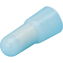
Insulated Crimp Terminal, Closed End Connector【100 pieces】
Click image to view enlarged image
Part number:
possible part numbers found.Product specifications
Specifications

| 1-pack | 100-piece Pack |
| Model | Color |
| CE-1 | Milky White |
| CE-2 | |
| CE-5 | |
| CE-8 |
More Information

External Dimensions Table and Specifications
| Model | Insulation Material | Rated Voltage | Operating Temperature Range | External Dimensions (Unit: mm) | Weight (g) | Compatible Tool | |||||||
| A | B | C | D | E | F | G | H | ||||||
| CE-1 | Nylon | 300V | -40°C ~ +105°C | 2.4 | 7.0 | 0.5 | 5.0 | 6.5 | 20.0 | 9.5 | 0.8 | 0.62 | 7GOU-A |
| CE-2 | 3.0 | 7.1 | 5.6 | 7.8 | 9.3 | 0.80 | 8GOU / 7GOU-A | ||||||
| CE-5 | 4.0 | 8.1 | 0.8 | 7.3 | 9.4 | 23.0 | 10.5 | 0.9 | 1.46 | 8GOU / 7GOU-A | |||
| CE-8 | 5.0 | 9.5 | 1.0 | 9.0 | 10.4 | 28.0 | 11.8 | 2.57 | 8GOU | ||||
Electric Wire Combination Table
(How to Use the Table)
In the case of CE-1, for example, this means that for a single standard wire of 0.3 mm2, the possible combinations of wire size and number of wires are from 1 to 3 for 0.3 mm2, or from 1 to 2 for 0.5 mm2, or 1 for 0.75 mm2.
| Model | Wire Conjugation Range | Reference Wire Size | Wire Size mm2 (AWG) and Possible Bundle Number | |||||||
| mm2 | mm2 (AWG) | Count | 0.3 (22) | 0.5 (20) | 0.75 (18) | 1.25 (16) | 2.0 (14) | 3.5 (12) | 5.5 (10) Stranded Wire | |
| CE-1 | 0.5 ~ 1.25 | 0.3 (22) | 1 | 1 ~ 3 | 1 ~ 2 | 1 | 1 | — | — | — |
| 2 | 1 ~ 2 | 1 | 1 | — | — | — | — | |||
| 3 | — | 1 | 1 | — | — | — | — | |||
| 0.5 (20) | 1 | 1 ~ 3 | — | — | — | — | — | — | ||
| 2 | 1 ~ 2 | — | — | — | — | — | — | |||
| 0.75 (18) | 1 | 1 ~ 2 | 1 | 1 | — | — | — | — | ||
| 1.25 (16) | 1 | 1 | 1 | — | — | — | — | — | ||
| CE-2 | 1.0 ~ 3.0 | 0.3 (22) | 1 | 3 ~ 7 | 2 ~ 4 | 1 ~ 2 | 1 ~ 2 | 1 | — | — |
| 2 | — | 1 ~ 3 | 1 ~ 2 | 1 | 1 | — | — | |||
| 3 | — | 1 ~ 3 | 1 ~ 2 | 1 | 1 | — | — | |||
| 0.5 (20) | 1 | 2 ~ 6 | 1 ~ 4 | 1 ~ 2 | 1 ~ 2 | 1 | — | — | ||
| 2 | 1 ~ 5 | — | 1 ~ 2 | 1 | 1 | — | — | |||
| 3 | 1 ~ 4 | — | 1 ~ 2 | 1 | — | — | — | |||
| 0.75 (18) | 1 | 1 ~ 5 | 1 ~ 3 | 1 ~ 2 | 1 | 1 | — | — | ||
| 2 | 1 ~ 4 | 1 ~ 2 | 1 | 1 | — | — | — | |||
| 3 | 1 ~ 2 | 1 | — | — | — | — | — | |||
| 1.25 (16) | 1 | 1 ~ 4 | 1 ~ 2 | 1 ~ 2 | 1 | — | — | — | ||
| 2.0 (14) | 1 | 1 ~ 2 | 1 | 1 | — | — | — | — | ||
| CE-5 | 2.5 ~ 6.0 | 0.3 (22) | 1 | 7 ~ 9 | 5 ~ 9 | 3 ~ 6 | 2 ~ 3 | 2 | 1 | 1 |
| 2 | — | 4 ~ 8 | 3 ~ 6 | 2 ~ 3 | 1 | 1 | — | |||
| 3 | — | 4 ~ 7 | 3 ~ 5 | 2 | 1 | 1 | — | |||
| 0.5 (20) | 1 | 7 ~ 8 | 4 ~ 7 | 3 ~ 5 | 2 ~ 3 | 1 ~ 2 | 1 | 1 | ||
| 2 | 5 ~ 7 | — | 2 ~ 4 | 1 ~ 2 | 1 ~ 2 | 1 | — | |||
| 3 | 3 ~ 5 | — | 2 ~ 3 | 1 ~ 2 | 1 ~ 2 | 1 | — | |||
| 0.75 (18) | 1 | 6 ~ 8 | 4 ~ 7 | 2 ~ 4 | 2 ~ 3 | 1 ~ 2 | 1 | — | ||
| 2 | 4 ~ 6 | 1 ~ 5 | — | 1 ~ 2 | 1 ~ 2 | 1 | — | |||
| 3 | 1 ~ 5 | 1 ~ 3 | — | 1 ~ 2 | 1 | 1 | — | |||
| 1.25 (16) | 1 | 5 ~ 8 | 3 ~ 4 | 2 ~ 4 | 1 ~ 2 | 1 ~ 2 | 1 | — | ||
| 2 | 1 ~ 6 | 1 ~ 3 | 1 ~ 2 | — | 1 | — | — | |||
| 3 | 1 ~ 5 | 1 ~ 2 | 1 ~ 2 | — | — | — | — | |||
| 2.0 (14) | 1 | 2 ~ 7 | 1 ~ 4 | 1 ~ 4 | 1 ~ 2 | 1 ~ 2 | 1 | — | ||
| 3.5 (12) | 1 | 1 ~ 6 | 1 ~ 4 | 1 ~ 2 | 1 | 1 | — | — | ||
| CE-8 | 4.0 ~ 9.0 | 0.5 (20) | 1 | — | 7 ~ 12 | 5 ~ 8 | 3 ~ 4 | 2 ~ 3 | 1 ~ 2 | 1 |
| 2 | — | — | 4 ~ 7 | 2 ~ 4 | 2 ~ 3 | 1 ~ 2 | 1 | |||
| 3 | — | — | 4 ~ 7 | 2 ~ 4 | 2 | 1 | 1 | |||
| 4 | — | — | 3 ~ 6 | 1 ~ 3 | 1 ~ 2 | 1 | 1 | |||
| 5 | — | — | 2 ~ 5 | 1 ~ 3 | 1 ~ 2 | 1 | 1 | |||
| 6 | — | — | 2 ~ 4 | 1 ~ 2 | 1 | 1 | 1 | |||
| 0.75 (18) | 1 | — | 7 ~ 11 | 5 ~ 8 | 3 ~ 4 | 2 ~ 3 | 1 ~ 2 | 1 | ||
| 2 | — | 5 ~ 10 | — | 2 ~ 4 | 2 | 1 ~ 2 | 1 | |||
| 3 | — | 4 ~ 9 | — | 2 ~ 3 | 1 ~ 2 | 1 | 1 | |||
| 4 | — | 2 ~ 8 | — | 1 ~ 2 | 1 ~ 2 | 1 | 1 | |||
| 5 | — | 1 ~ 6 | — | 1 ~ 2 | 1 | 1 | — | |||
| 1.25 (16) | 1 | — | 7 ~ 11 | 4 ~ 8 | 3 ~ 4 | 2 | 1 | 1 | ||
| 2 | — | 5 ~ 10 | 2 ~ 6 | — | 1 ~ 2 | 1 | — | |||
| 3 | — | 1 ~ 7 | 1 ~ 4 | — | 1 ~ 2 | 1 | — | |||
| 4 | — | 1 ~ 6 | 1 ~ 3 | — | 1 ~ 2 | 1 | — | |||
| 2.0 (14) | 1 | — | 7 ~ 10 | 3 ~ 7 | 2 ~ 4 | 1 ~ 2 | 1 | 1 | ||
| 2 | — | 1 ~ 8 | 1 ~ 4 | 1 ~ 2 | — | 1 | — | |||
| 3 | — | 1 ~ 5 | 1 ~ 2 | 1 ~ 2 | — | — | — | |||
| 3.5 (12) | 1 | — | 1 ~ 8 | 1 ~ 5 | 1 ~ 2 | 1 | 1 | 1 | ||
| 2 | — | 1 ~ 2 | 1 ~ 2 | 1 | 1 | — | — | |||
| 5.5 (10) Stranded Wire | 1 | — | 1 ~ 5 | 1 ~ 4 | 1 ~ 3 | 1 | 1 | — | ||
More Information
Basic information
Closed-ended connector compliant with JIS standards. 1 pack contains 100 pieces

● Most commonly used crimp closed-end connectors with insulation. Any number of wires can be bundled together and connected.
● JIS (JQ0608005), UL (E74917) and CSA (LR66230) have been acquired.

· Use a dedicated tool for crimping.
· As it is not waterproof, use only in places where it cannot come into contact with water.
· Available from 1 pack (100 pieces).
Common specifications
Features
● Crimp terminals are wire connection components that are used in a wide range of applications such as electrical engineering as well as domestic electrical appliances, measuring devices, FA control devices etc.● Available in 2 types: conventional type bare crimp terminals without insulation sheathing, and crimp terminals with insulation sleeves.
● We also offer products with JIS, UL and CSA certification, allowing for use with peace of mind.
Allowable Current
| Wire Size Used | Terminal Nominal Number |
Allowable current or less (at 30°C) | ||||
|---|---|---|---|---|---|---|
| Single Wire | Stranded Wire | AWG | With rubber vinyl insulated wire | Cord | ||
| Single Wire | Stranded Wire | |||||
| - | 0.08 | 28 | 0.08 | - | - | - |
| - | 0.3 | 26, 24 | 0.3 | - | - | - |
| 0.8 | 0.3, 0.5 | 22, 20 | 0.5 | - | - | - |
| 1.0, 1.2 | 0.75, 0.9, 1.25 | 18, 16 | 1.25 | 16 A, 19 A | 16 A, 17 A, 19 A | 7 A (0.75 mm), 12 A |
| 1.6 | 2 | 14 | 2 | 27 A | 27 A | 17 A |
| 2.0 | 3.5 | 12 | 3.5 | 35 A | 37 A | 23 A |
| 2.6 | 5.5 | 10 | 5.5 | 48 A | 48 A | 35 A |
| 3.2 | 8 | 8 | 8 | 62 A | 62 A | - |
Allowable Voltage
Bare Crimp Terminal: 600 VAC or lessInsulated Crimp Terminal: 300 VAC or less
Materials
Conductor Component: Oxygen-free Copper (Tin-Plated)Insulator Component: Refer to product pages
Compatible Wire Size
Refer to product pages.Crimping Method
Diagram A
| Terminal Nominal (Note 3) |
Wire Size Used | Wire Sheath Strip Dimensions (mm) | ||||
|---|---|---|---|---|---|---|
| Stranded Wire (mm2) | Single Wire (Dia. mm) |
Wire Conjugation Capacity (Note 1) |
L (Note 2) |
L1 | L2 | |
| 0.08 | 0.08 | - | - | B + L1 + L2 | 0.5 ~ 2 | 0 ~ 1 |
| 1.25 | 0.3, 0.5, 0.75, 0.9, 1.25 |
0.75 ~ 1.44 | 0.25 ~ 1.65 | B + L1 + L2 | 0.5 ~ 2 | 0 ~ 1 |
| 2 | 1.25, 2.0 | 1.14 ~ 1.82 | 1.04 ~ 2.63 | B + L1 + L2 | 0.5 ~ 2 | 0 ~ 1 |
| 5.5 | 3.5, 5.5 | 1.82 ~ 2.89 | 2.63 ~ 6.64 | B + L1 + L2 | 0.5 ~ 2 | 0 ~ 1 |
| 8 | 8 | 2.89 ~ 3.65 | 6.64 ~ 10.52 | B + L1 + L2 | 1 ~ 2 | 0 ~ 2 |
(Note 2) The calculation method of the L dimension is simply for finding the dimensions of the wire sheath stripping, and is not used to indicate the shape or dimensions after crimping.
(Note 3) For applicable wires at 0.3, use a conductor cross-sectional area close to the terminal nominal. Furthermore, fold back the core wire when crimping thin types such as AWG28.
Also, ensure that the wire stripping dimension complies with the terminal nominal 1.25.
Crimping Guideline

Selection of Crimping Tool

Visual Inspection after Crimping
