- [D] Diameter (Shaft)(mm)
- 10
- 12
- 13
- 16
- 20
- 25
- 30
- 35
- 40
- 50
- [L] Length (Shaft)(mm)[200-1500/1mm units]
- Material
- Alloyed Steel
- EN 1.3505 Equiv.
- Stainless Steel (martensitique)
- EN 1.4037 Equiv.
- Surface Treatment
- CAD
- 2D
- 3D
- Est. shipping days
- All
- Within 7 working days
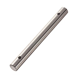
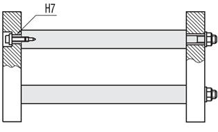
Linear shafts / radial bore with internal thread

Mouse over image to enlarge
Part number:
possible part numbers found.Outline drawing and specifications table

K: Number of Pitches
 ; and for unplated products, it is
  .
.[ ! ] The dimension tolerances for L and P conform to JIS B 0405 Class m.
[ ! ] Machined areas may be out of O.D. tolerances due to annealing-induced deformation.
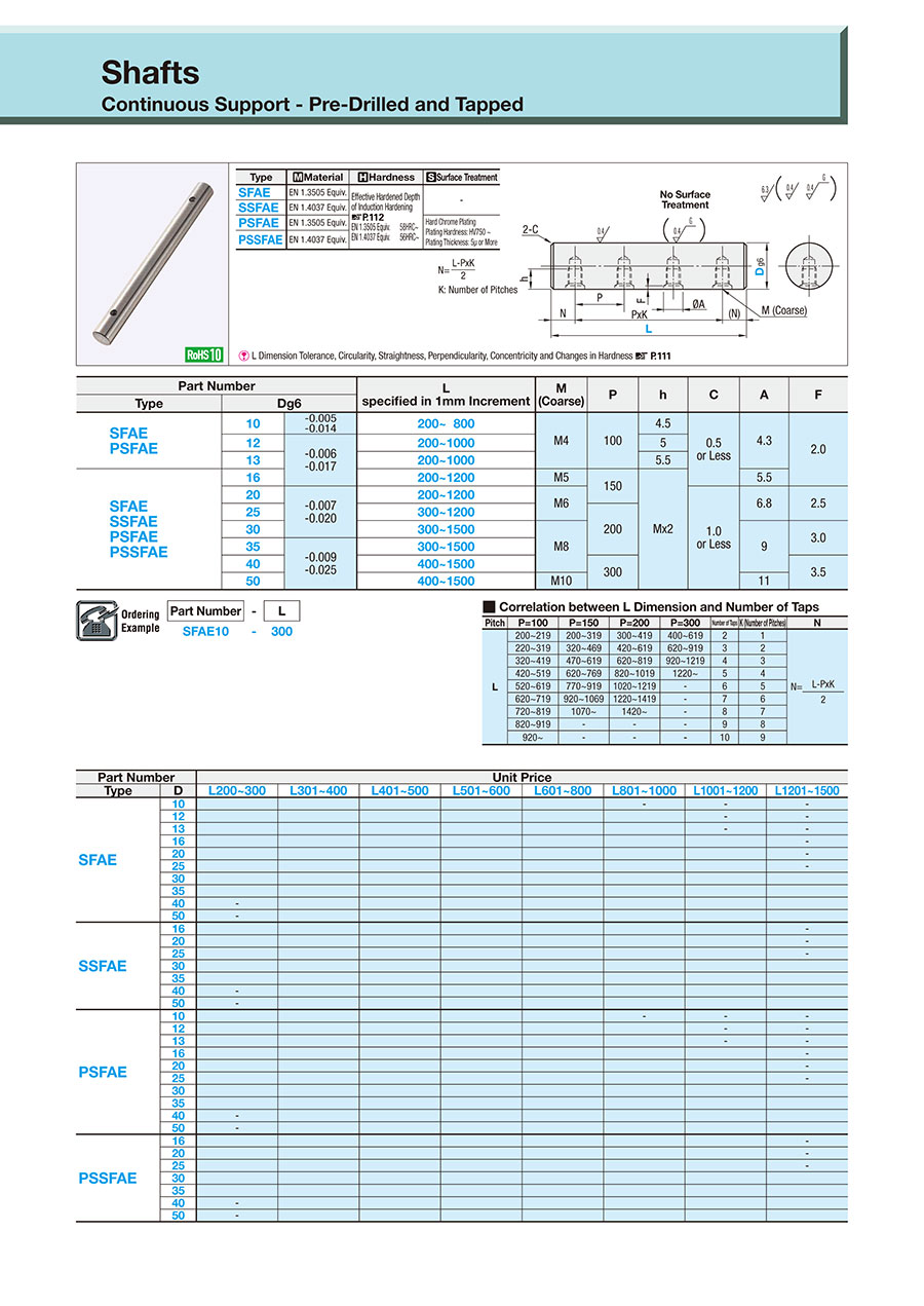
| Type | [M] Material | [H] Hardness | [S]Surface Treatment |
| SFAE | EN 1.3505 Equiv. | Induction Hardened EN 1.3505 Equiv. 58HRC~ EN 1.4125 Equiv. 56HRC~ | — |
| SSFAE | EN 1.4125 Equiv. | ||
| PSFAE | EN 1.3505 Equiv. | Hard Chrome Plating Plating Hardness: HV750 or more Plating Thickness: 5µ or More | |
| PSSFAE | EN 1.4125 Equiv. |
Specification Table
| Part Number | — | L |
| SFAE10 | — | 300 |
| Part Number | L 1 mm Increments | M (Coarse) | P | h | C | A | F | ||
| Type | Dg6 | ||||||||
| SFAE PSFAE | 10 | −0.005 −0.014 | 200 to 800 | M4 | 100 | 4.5 | 0.5 or Less | 4.3 | 2.0 |
| 12 | −0.006 −0.017 | 200 to 1000 | 5 | ||||||
| 13 | 200 to 1000 | 5.5 | |||||||
| SFAE SSFAE PSFAE PSSFAE | 16 | 200 to 1200 | M5 | 150 | M × 2 | 5.5 | |||
| 20 | −0.007 −0.020 | 200 to 1200 | M6 | 1.0 or Less | 6.8 | 2.5 | |||
| 25 | 300 to 1200 | 200 | |||||||
| 30 | 300 to 1500 | M8 | 9 | 3.0 | |||||
| 35 | −0.009 −0.025 | 300 to 1500 | |||||||
| 40 | 400 to 1500 | 300 | 3.5 | ||||||
| 50 | 400 to 1500 | M10 | 11 | ||||||
| Pitch | P = 100 | P = 150 | P = 200 | P = 300 | Number of Taps | K (Number of Pitches) | N | ||
| L | 200 to 219 | 200 to 319 | 300 to 419 | 400 to 619 | 2 | 1 | N =
| ||
| 220 to 319 | 320 to 469 | 420 to 619 | 620 to 919 | 3 | 2 | ||||
| 320 to 419 | 470 to 619 | 620 to 819 | 920 to 1219 | 4 | 3 | ||||
| 420 to 519 | 620 to 769 | 820 to 1019 | 1220 or more | 5 | 4 | ||||
| 520 to 619 | 770 to 919 | 1020 to 1219 | — | 6 | 5 | ||||
| 620 to 719 | 920 to 1069 | 1220 to 1419 | — | 7 | 6 | ||||
| 720 to 819 | 1070 or more | 1420 or more | — | 8 | 7 | ||||
| 820 to 919 | — | — | — | 9 | 8 | ||||
| 920 or more | — | — | — | 10 | 9 |
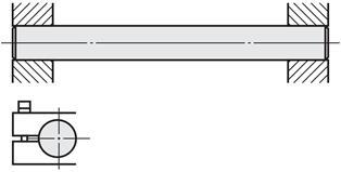
Circularity (M), Straightness (K), L Dimension Tolerance, Perpendicularity
■Straightness Measurement Method

Shaft ends are supported on V-blocks and turned 360 degrees to
measure shaft runout using a dial indicator.
1/2 of measured runout is defined as the straightness.
Shaft Outer Dia. g6 (Hardening)
| D | Circularity M | |
|---|---|---|
| Over | or Less | |
| 9 | 13 | 0.004 |
| 13 | 20 | 0.005 |
| 20 | 40 | 0.006 |
| 40 | 50 | 0.007 |
Shaft Outer Dia. g6 (Hardening)
| D | L | Straightness K | |
|---|---|---|---|
| 10 to 50 | L ≤ 100 | 0.01 or Less | |
| L > 100 | (L/100) × 0.01 or Less | ||
Shaft Outer Dia. g6 (Hardening)
| L | L Dimension Tolerance | |
|---|---|---|
| Over | or Less | |
| 199 | 400 | ±0.5 |
| 400 | 1000 | ±0.8 |
| 1000 | 1500 | ±1.2 |
■ Perpendicularity

Notes on Surface Treating
■Reduced Hardness around Machined Areas
·Although processing is performed after the base material is hardened, annealing may lower hardness of the machined area.
* Reduced Hardness: Approximately 10 to 40 HRC
* Machined areas may be out of O.D. tolerances due to annealing-induced deformation.
■Reduced Hardness Range
·Approximately 10 mm from the machined area

■Reduced Hardness Condition of Tapped
The conditions for lower hardness for tapped differ depending on the material and selection conditions.
- EN 1.4125 Equiv. : The hardness of the tapped part will decrease.
- EN 1.3505 Equiv.: Under the following conditions, the hardness of the tapped will decrease.
·When M ≥ D/2, · RC thread, · One End Two Tapped Holes
■Effective Hardened Layer Depth of Hardening
The effective hardened layer depth varies depending on the external dimensions and materials.
| O.D. D | Effective Hardened Layer Depth | |||
|---|---|---|---|---|
| EN 1.3505 Equiv. | EN 1.4125 Equiv. | |||
| 10 | 0.5 or More | 0.5 or More | ||
| 12·13 | 0.7 or More | |||
| 16·20 | 0.7 or More | |||
| 25 to 50 | 1.0 or More | |||
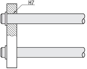
■About hard chrome plating and plating layer of processed part
- Hard chrome plating is applied after surface treatment of the base material, so there is no plating on the processed parts.
- In the example below, only "///" area is treated with hard chrome plating.
/// Part: Plating Remains

Part number list
| Part number |
|---|
Unit price (excluding VAT)(Unit price including VAT) | Standard shipping days |
|---|
- ( - ) | 7 working days |
- ( - ) | 7 working days |
- ( - ) | 7 working days |
- ( - ) | 7 working days |
- ( - ) | 7 working days |
- ( - ) | 7 working days |
- ( - ) | 7 working days |
- ( - ) | 7 working days |
- ( - ) | 7 working days |
- ( - ) | 7 working days |
- ( - ) | 7 working days |
- ( - ) | 7 working days |
- ( - ) | 7 working days |
- ( - ) | 7 working days |
- ( - ) | 7 working days |
- ( - ) | 7 working days |
- ( - ) | 7 working days |
- ( - ) | 7 working days |
- ( - ) | 7 working days |
- ( - ) | 7 working days |
- ( - ) | 7 working days |
- ( - ) | 7 working days |
- ( - ) | 7 working days |
- ( - ) | 7 working days |
- ( - ) | 7 working days |
- ( - ) | 7 working days |
- ( - ) | 7 working days |
- ( - ) | 7 working days |
- ( - ) | 7 working days |
- ( - ) | 7 working days |
- ( - ) | 7 working days |
- ( - ) | 7 working days |
- ( - ) | 7 working days |
- ( - ) | 7 working days |
More Information
Basic information
Outline and specifications
Surface Limits / Hardness - Linear Shafts
Limits of hardness and hardening depth
The linear shafts are processed after the base material has undergone inductive hardening. Therefore, the processed surfaces may result in a deviating hardness.
In the following example, you can view the affected areas of the linear shaft, which may be affected after processing by e.g. threads, level surfaces, key surfaces and transverse bores.
_(450x164).jpg)
Cause for deviating hardness
The raw material of the linear shaft is treated via thermal induction before grinding. Thus, a configured linear shaft can be custom-made not only cost-effectively, but also with short delivery times. The linear shaft is hardened at the boundary layer (boundary layer hardening) of the liner shaft. The depth of the hardened boundary layer depends on the material used and the diameter of the linear shaft. The following table shows the hardening depth of linear shafts.
Coatings and plating are applied to the raw material after hardening and grinding. For more information, see Coatings of the Linear Shaft.
.jpg)
Figure of boundary layer hardening: hardened boundary layer in light gray
Effective hardening depth of linear shafts
| Outside diameter (D) | Effective hardening depth | |||
| EN 1.1191 equiv. | EN 1.3505 equiv. | EN 1.4125 equiv. | EN 1.4301 equiv. | |
| 3 | - | +0.5 | +0.5 | Without induction hardening |
| 4 | - | |||
| 5 | - | |||
| 6 - 10 | +0.3 | |||
| 12 - 13 | +0.5 | +0.7 | +0.5 | |
| 15 - 20 | +0.7 | |||
| 25 - 50 | +0.8 | +1 | ||
Overview of the effective hardening depth as PDF
Coatings of the linear shaft
The surface coating is applied to the raw material before machining the linear shaft. Thanks to their coating, the usable surface or work surface of the linear shaft is not only protected against corrosion but also against wear.
Machined positions of the linear shafts, such as plane surfaces or threads, may be uncoated, as they are added afterwards. This can lead to the machined surfaces being corroded in a linear shaft made of steel. If the linear shaft is used in a corrosive environment, it is recommended to use a stainless steel linear shaft.
The following figure shows the areas of the linear shaft that are coated (crosshatched).
_(321x64).jpg)
Figure: Coating of linear shafts
You can find further information on surface treatment and hardness in this PDF .
General Information - Linear Shafts
Linear Shaft Selection Details
- Material: steel, stainless steel
- Coating/plating: uncoated, hard chrome plated, LTBC coated, chemically nickel-plated
- Heat treatment: untreated, inductively hardened
- ISO tolerances: h5, k5, g6, h6, h7, f8
- Precision classes: perpendicularity 0.03, concentricity (with thread and increments) Ø0.02, perpendicularity 0.20, concentricity (thread and stepper) Ø0.10
- Linearity/roundness: depends on diameter, here for the PDF
Description / basics of the linear shaft
Linear shafts are steel shafts that perform guiding tasks in combination with linear bearings, such as plain bearing bushings or linear ball bushings. Linear shaft holding functions can be adopted from shaft holders or linear ball bearing adapters. Most linear shafts are heat-treated (induction hardened) solid shafts. A special design of linear shafts is the hollow shaft, which is also called tubular shaft. Inductively hardened linear shafts have a high surface hardness and a tough core. The achievable surface hardness is approx. 55-58 HRC (see information on hardening depth). Linear shafts made of stainless steels can generally not be hardened. Therefore, these steel shafts should be chrome plated to protect them from wear.
Materials
Linear shafts are mainly hardened steel shafts. In addition to the selected heat treatment, the steel used in particular imparts its properties to the linear shaft, although it is a hollow shaft or a solid shaft. Therefore, special aspects such as hardness, corrosion and wear must be considered when selecting the shaft steel.
Coatings
To protect linear shafts from corrosion, the surface can be chemically nickel-plated. As an alternative to chemical nickel-plating, steel shafts can also be coated with LTBC. The LTBC coating is an anti-corrosive surface coating and it is a low-reflection coating, made of a 5 μm thick film of fluoropolymer, which in essence is a black film. In addition, the LTBC coating is resistant to bursting pressure by extreme or repeated bending. LTBC-coated linear shafts are thus particularly suitable for locations where corrosion or light reflections are undesirable. Linear shafts that require particularly high surface hardness and wear resistance can be hard chrome plated.
Function
The form and function of linear shafts differ from linear guiderails. Linear guiderails are square rails that work in combination with carriers (rotary elements, carriages) according to the rolling or sliding principle. Linear shafts on the other hand are precision-ground round steel shafts that take on a linear guide function in conjunction with linear ball bushings or plain bearing bushings (maintenance-free bushings).
Areas of Application
Linear shafts are intended for axial motion. Whether horizontal or vertical linear motion, all linear motions can be implemented with linear shafts. Common applications are stroke mechanisms and other applications with high demands on smoothness, precision and service life. Linear shafts can therefore be used in almost all industries of plant construction and mechanical engineering. Linear shafts are often found in 3D printers, metering equipment, measuring devices, positioning devices, alignment devices, bending devices and sorting equipment.
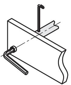
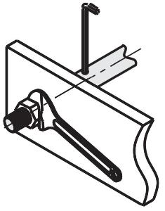
Instructions for Use / Installation - Linear Shafts
For product selection, please observe the linear shaft tolerances (e.g. h5, k5, g6, h6, h7, f8) in conjunction with the diameter tolerance of the plain bearing bushing (sliding bearing) after pressing in or the running circle diameter of the linear ball bearing (ball bushing).
.jpg)
.jpg)
.jpg)
.jpg)

_M0102000000_.jpg)
Adjusting rings/clamping rings
_M0103000000_.jpg)
_M0104000000.jpg)
_M0107080000.jpg)
_M0105000000.jpg)