Currently there are no notifications.
Balls screws and lead screws
-

Thread Diameter 10/Lead 2/4 or 10 -

Precision Ball Screws/Shaft Diameter 6 or 8/Lead 1 or 2 -

Rolled Ball Screws 8 - 32 -

Configure and order now -

Precision Ball Screws Diameters 12/ Lead 2/4/5 or 10 -

Rolled Ball Screws/Compact Nut/Shaft Dia. 12/Lead 4 -

Precision Ball Screws, Thread Diameters 15, Lead 5/10/20 -

PDF - at a glance
MISUMI offers a wide range of ball screws and lead screws. You can select between precision and rolled ball screws. Parameters, such as length and shape of the shaft end and the nut form, can be configured according to your design. For the spindle nuts with acme thread, you can choose between different models, such as block flange, round flange or square flange.
Rolled ball screws with up to 40% less volume
The rolled ball screw type and corresponding compact nuts offer up to 40% lower nut capacity. Of course, standard nuts and guide nuts are also available.
Various shaft end options
Several options are available for the shaft end of the ball screw:
Support side
- No machining of the shaft end
- Reversed ball nut alignment
- No safety groove on the shaft end of the support side
- Other processing of the shaft end of the support side
- Other length of the shaft end of the support side
Fixed side
- Key areas on the fixed side
- Groove on the shaft end of the fixed side
- Up to 2 clamping surfaces at the shaft end
Available lubricants for ball screws
The lubricants of the ball screws can be changed from the standard version to the following types. The versions L or G permit proper operation by low particle emission during operation.
The choices are:
- ET-100 with excellentheat resistance/oxidationresistance and adhesion strength/cohesion strength, as well as minimum splashand low
- LG2 as cleanroom qualified special lubricantforlinear guides, ball screws, etc.
Selection of Ball Screws
The standard selection procedure for right ball screw:
1) Decide on operating conditions of the ball screw:
weight per part, movement speed, movement pattern, speed of threaded shaft, strokes, mounting direction (horizontal or vertical), life, positioning.
2) Preliminarily select the specifications for the ball screw according to the operating conditions:
precision category, shaft diameter, thread pitch and length of threaded shaft of ball screw.
3) Standard safety check:
Check permissible axial load:
Make sure that the value of the axial load is within the safe range of permissible values for the threaded shaft.
Check permissible speed:
Make sure that the speed of the screw shaft is within the safe range of permissible values for the threaded shaft.
Operating time:
Calculate the lifetime of the threaded shaft and make sure that it is suitable for the required operations.
Depending on the results of the safety check, it might be necessary to return to Step 1 and Step 2 to make adjustments to the setup. If the standard safety check is passed, continue to Step 4.
4) Considerations for required performance:
The following confirmations are necessary if higher positioning speed and better control behaviour are required:
Strength of threaded shaft Operating time variations due to temperature variations
Depending on the results of these considerations, returning to Steps 1 and 2 might be necessary in order to make corresponding adjustments.
Permissible axial load of ball screws
The allowable axial load represents the maximum load, including safety limits, which causes a bulging of the shaft. The maximal axial load on the threaded shaft must be less than or equal to the value for the permissible axial load.
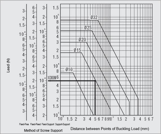
1. Calculating the permissible axial load
Determine the value of the curve to the allowable axial load on the Ball Screw using the following three factors:
- Thread shaft-Ø
- Mounting aid procedure
- Distance between load points of action
* Use a formula in order to determine the exact value for the permissible axial load.
2. Calculation of maximal axial load
Use the following formulas to determine each axial acceleration, constant speed and deceleration (when installed horizontally). The largest load is considered the maximum axial load:
- Constant speed ··· axial load (Pb)=μWg
- Acceleration ··· axial load (Pa)=W +μWg
- Delay ··· axial load (Pc)=W -μWg
*For vertical installation remove the "μ" from the calculation.
μ: linear guide friction constant (0:02 for the linear guides)
W: weight of parts
g: acceleration due to gravity 9.8 m/s2
α : acceleration (*)
(*) acceleration (α)=(Vmax/t)x10-3
Vmax: quick delivery speed
t: acceleration/deceleration time
3. Safety check
Check the curve for the permissible axial load to ensure that the value for the maximum axial load is less than or equal to the value for the permissible axial load.
Video - Introduction ball screws
These videos were kindly provided to us by our USA subsidiary. Therefore, contact the US subsidiary for all related details. All products are also available in Europe.