Currently there are no notifications.
Worm Gear – Low-Noise Gear Ratio Expert
Worm gears are an important part of the design of many machines and systems. They offer high gear ratios and torque transmission, while taking up only little space in mechanical application thanks to their space-saving design. In order to find the best possible solution for your specific requirements, it is important to select the right components based on the required specifications and performance requirements.
What worm gears are and what they are used for
Worm gears are a torque transfer mechanism and consist of a worm and a gear wheel (worm wheel). Worm gears convert rotary movements into another rotary movement with a very high reduction or transfer ratio and are used to enable high torque at a low speed.
Due to the shape and geometry of the worm gears, they have an extremely low noise and vibration behavior in operation. They are able to provide high torque at low speed of rotation, making them ideal for applications such as lifting and material transport equipment. You can continue working unidirectionally, which means that the worm wheel cannot transfer the torque to the worm.

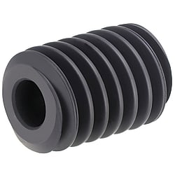
- (a) - worm shaft
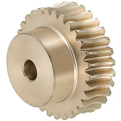
- (b) - worm wheel
What components does a worm gear system consist of?
A worm gear consists of the following two main components:
Worm Shaft: A spiral-shaped shaft, which converts the input torque into a rotational movement and transfers it to the worm wheel. Usually, the worm acts as a drive on the worm wheel. The worm may have one or more threads that engage in the gear rim of the worm gear.
Worm wheel: A wheel with a bevelled gear rim that absorbs the rotational movement of the worm and transfers it to the output torque.
Basics for the selection of worm gears
The calculation principles for worm gears are multidimensional and require a comprehensive understanding of the mechanics and geometry. The most important points when selecting a suitable worm gear are:
The calculation principles for worm gears are multidimensional and require a comprehensive understanding of the mechanics and geometry. The most important points when selecting a suitable worm gear are:
- Gear ratio: The gear ratio of a worm gear is determined by the ratio of the number of teeth (z). To determine, the number of teeth of the worm wheel is divided by the number of turns of the worm.
- Torque transmission: The maximum permissible torque of worm gears is largely determined by the strength of the tooth surfaces and must not be exceeded during application in order to achieve a long service life.
- Engagement distance: The distance between the centres of axle of the worm and worm wheel must be determined.
- Load-bearing capacity: The load-bearing capacity of worm gears is largely determined by the material pairing of the worm and the worm wheel. The load-bearing capacity limits are calculated on the basis of DIN 3996.
Which components are required for efficient worm gears?
Worm gears are mounted on drive shafts, rotation shafts and motor shafts. The worm gear transfers the engine torque to other parts of the system. The fixation on the drive shaft can be carried out, for example, using grub screws, which ensure that the components are securely connected to each other. Bearing housings can be used to ensure permanent positioning of this drive segment. They serve to stabilize the shaft and thus the entire system. The solid interlocking of these components ensures that all elements can work together optimally without causing unnecessary friction forces.
Worm Shaft and Worm Wheel Specifications

Worm Shaft Specifications
| Part number | Number of threads | Shaft bore Ø PH7 | Direction of rotation | Thread angle | d | D | L | ℓ | |
|---|---|---|---|---|---|---|---|---|---|
| Design | Module | Straight bore hole + thread | |||||||
| WGEAU | 0.8 | 1 | 6 | R (Right) |
3 ̊17' | 14 | 15.6 | 30 | 5 |
| 2 | 6 | 6 ̊34' | |||||||
| 1 | 1 | 6 | 3 ̊35' | 16 | 18 | 32 | 5 | ||
| 2 | 6 | 7 ̊11' | |||||||
Worm Wheel Specifications
| Part number | Number of teeth | Number of threads | Shaft bore Ø PH7 | Direction of rotation | d | D | B | H | L | ℓ | F Engagement distance | Permissible torque (Nm) | Clearance (mm) | Reduction ratio | |
|---|---|---|---|---|---|---|---|---|---|---|---|---|---|---|---|
| Design | Module | Straight bore hole | Strength of the tooth surface | ||||||||||||
| WGEAH | 0.8 | 20 | 2 | 5 | R (Right) |
16.11 | 17.6 | 9 | 12 | 18 | 9 | 15 | 0.86 | 0.04~022 | 1/10 |
| 30 | 1 | 5 | 24.04 | 25.6 | 18 | 19 | 1.89 | 1/30 | |||||||
| 2 | 24.16 | 25.6 | 18 | 19 | 1.87 | 1/15 | |||||||||
| 40 | 1 | 6 | 32.05 | 33.6 | 20 | 23 | 3.24 | 1/40 | |||||||
| 50 | 1 | 8 | 40.06 | 41.6 | 25 | 27 | 4.90 | 1/50 | |||||||
| 1 | 20 | 1 | 6 | 20.05 | 23 | 10 | 16 | 20 | 10 | 18 | 1.58 | 0.06~0.24 | 1/20 | ||
| 2 | 20.16 | 23 | 16 | 18 | 1.54 | 1/10 | |||||||||
| 30 | 1 | 6 | 30.07 | 33 | 20 | 23 | 3.38 | 1/30 | |||||||
| 2 | 30.24 | 33 | 20 | 23 | 3.35 | 1/15 | |||||||||
| 40 | 1 | 8 | 40.08 | 43 | 26 | 28 | 5.79 | 1/40 | |||||||
| 50 | 1 | 8 | 50.1 | 53 | 30 | 33 | 8.76 | 1/50 | |||||||
Choose the right lubricant
Due to the high friction between the worm and the worm wheel, worm gears generate more heat than other types of gear units, which must be taken into account when selecting the correct lubrication and cooling. Lubrication in worm gears essentially has the following purposes:
- Reduction of sliding friction
- Temperature regulation
- Protection of the surfaces against corrosion
- Removal of foreign bodies
Different lubrication methods are suitable for the lubrication of worm gears. Choosing the correct lubrication method depends on the sliding speed between the contact surfaces. There are three different lubrication methods: Grease lubrication, immersion lubrication and forced lubrication.
| Lubrication process | Special features | Sliding speed |
|---|---|---|
| Grease lubrication | For lubrication, grease is applied manually to the tooth surfaces. This method is suitable at low engine speeds and lower torques. | up to 5 m/s |
| Immersion lubrication | During immersion lubrication, the worm gear is located in a closed container with an oil pan. The worm wheel dips with its teeth into the lubricating oil, which continuously wets the contact surfaces with lubricating oil. This method is suitable for medium engine speeds and medium torques | 5-10 m/s |
| Forced lubrication | The lubricating oil is introduced into the contact surface between the worm and worm wheel by means of gravity or via a pump. This method is suitable for high engine speeds and high torques. | from 10 m/s |
Maintenance of worm gears
Worm gears are of great importance in many construction applications. They are characterized by high precision and the capability to transfer large torques. Regular maintenance is essential for ensuring the longest possible service life and reliability.
One of the most important maintenance activities for worm gears is checking for proper lubrication. Because there is a high friction between the worm and worm wheels, worm gears develop more heat than other types of gear units, which must be taken into account when selecting the correct lubrication and maintenance.
Furthermore, inspecting the tooth flanks is of great importance for maintaining worm gears. These should be checked regularly for wear, damage or deformation. Damaged contact surfaces can lead to an increased material wear and malfunctions.
The following points should be observed during maintenance:
- Check the lubrication: The lubricating oil or lubricating grease must be checked regularly for dirt and contamination and replaced if necessary.
- Cleaning: Before relubricating or replacing the lubricating oil, the gear unit should be thoroughly cleaned to remove foreign bodies and deposits.
- Check for wear: Bearings, seals and contact surfaces should be checked regularly for wear. If necessary, worn parts may have to be replaced.
- Alignment check: Worm gears should be checked regularly for their alignment to prevent abrasion of the teeth.
Regular maintenance allows worm gears to work reliably and efficiently and reach their maximum service life.
Related articles


