Currently there are no notifications.
How to select the right component surface – Basic knowledge about surface roughness
Surface roughness and surface hardness are important properties that must be considered when selecting components. Although there are various methods to measure roughness or surface roughness of the surface of a component. However, these measurements often have to be converted to a standard dimension. This article explains how roughness properties can be determined according to the standards JIS B 0031, JIS B 0601, DIN EN or ISO.
What is surface roughness?
In most cases, the surfaces of materials do not have a regular structure. They contain deviations that are divided into roughness, ripples and shape.
The term surface roughness or roughness describes the unevenness of the surface height. In order to quantify the roughness, there are different calculation methods that consider the different properties of the surface.
The surface roughness can be influenced by various methods such as polishing, grinding or other surface treatment. Corrosion and wear behavior also play a role.
How is the surface roughness typically calculated?
The following parameters are important for calculating the components:
- Roughness curve = measured surface condition (2D)
- Ra = arithmetic roughness average
- Rz = ten-point roughness average
- Ry = maximum height
- Rmr = material portion or support portion
1. Measuring of the surface quality and determination of the roughness curve
In order to comprehensively and qualitatively check the surface quality of materials and components, it is necessary to check and analyze the surface in its entirety. For this purpose, scanning measuring tips or scanning devices are used to detect the vertical deflection of the scanning tip over the component surface. The information about the surface along one profile (2D) can thus be obtained, which is specified as a roughness curve. In order to ensure a comprehensive and high-quality examination of the surface quality, the surface must be considered and analyzed in its entirety.
2. Determine average roughness Ra
After determining the roughness curve, you "cut out" the part that extends over a reference length ℓ in the direction of the average line.
This cut-out part is illustrated as the size in a new X-axis graph in the same direction as the average line and Y-axis. Ra calculated with the following equation:
R_a = \frac{1}{l}\int_{0}^{l}f(x)dx
The average roughness Ra is typically indicated in micrometers [μm].

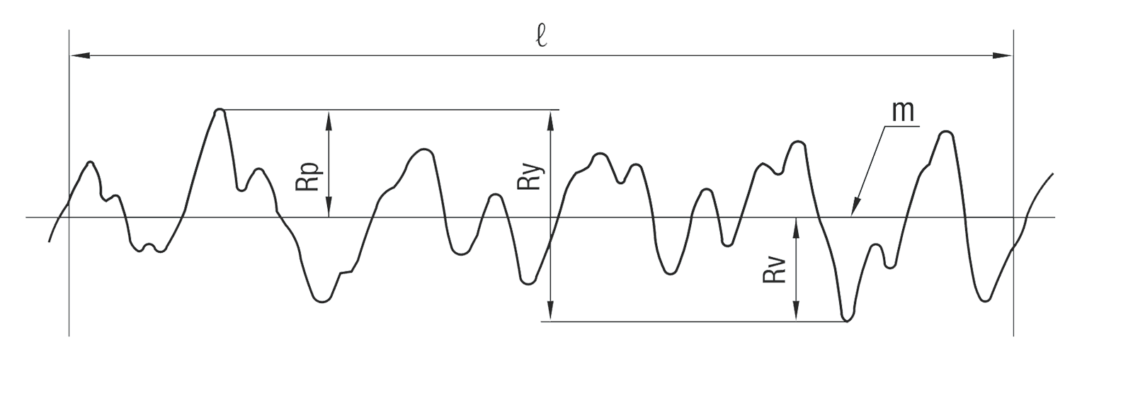
3. Determine the maximum height Ry
After determining the roughness curve, you "cut out" the part that extends over a reference length ℓ in the direction of the average line.
This cut-out part is illustrated as the size in a new X-axis graph in the same direction as the average line and Y-axis. Ry is calculated with the following equation:
R_y = |R_p|+|R_v|
The maximum height is, so to speak, the distance from the global minimum to the global maximum of the curve.
The maximum height Ry is typically specified in micrometers [μm].
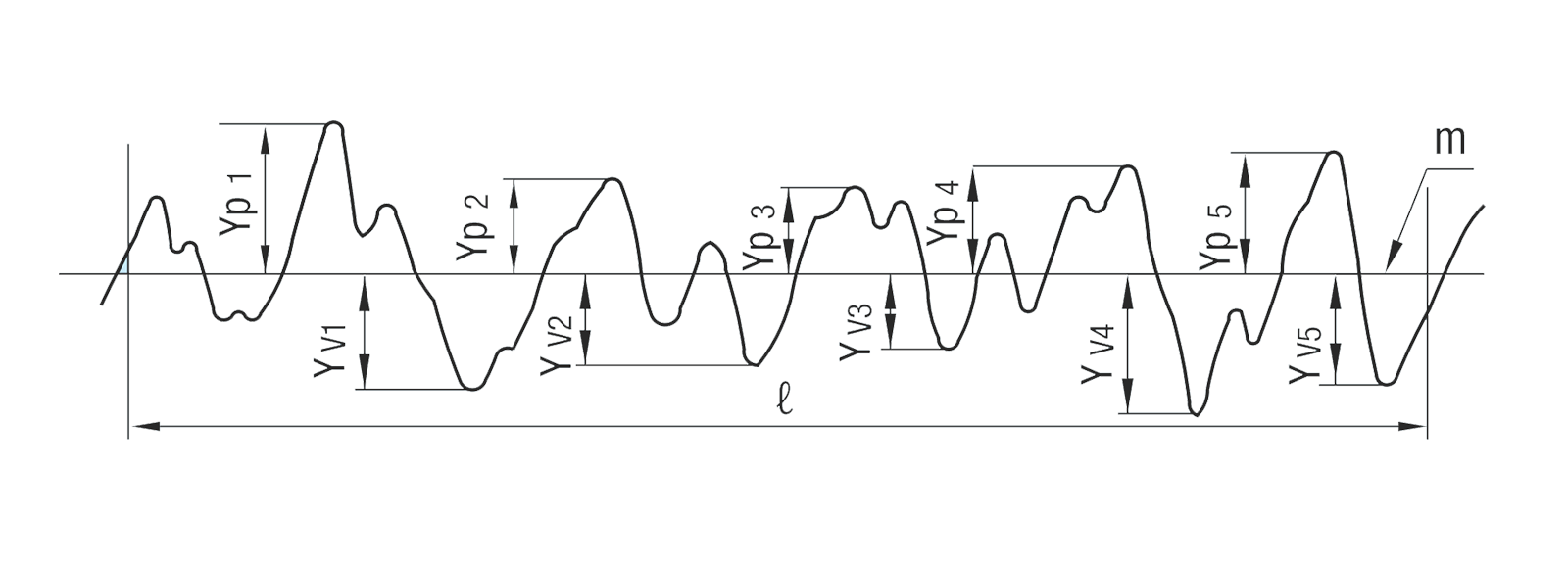
4. Determine ten-point roughness average Rz
After determining the roughness curve, you "cut out" the part that extends over a reference length ℓ in the direction of the average line.
The average values (YP) from the highest to the "fifth highest" peak value and the average values (Yv) from the lowest to the "fifth lowest" value are added:
R_z = \frac{∣Y_p1+Y_p2+Y_p3+Y_p4+Y_p5∣+∣Y_v1+Y_v2+Y_v3+Y_v4+Y_v5∣}{5}
The ten-point roughness average Rz is typically specified in micrometers [μm].
5. Determination of the material portion Rmr
After determining the roughness curve, you "cut out" the part that extends over a reference length ℓ in the direction of the average line.
The material portion is the portion of the positioning surface (a specific cutting line) relative to the observed reference length ℓ. The material portion is determined with the following formula:
R_{mr} = \frac{1}{l}\sum_{i=1}^{n}L_i
The material portion Rmr is typically specified in percent [%].
| Arithmetic roughness average Ra | Maximum height Ry | Ten-point average roughness Rz | Reference length of Ry (Rz) ℓ (mm) | Traditional symbol Surface treatment |
||||||||||||||||||||||||||||||||||||||||||||||||||||||||||||||||||||||||||||||||||||||||||||||||
|---|---|---|---|---|---|---|---|---|---|---|---|---|---|---|---|---|---|---|---|---|---|---|---|---|---|---|---|---|---|---|---|---|---|---|---|---|---|---|---|---|---|---|---|---|---|---|---|---|---|---|---|---|---|---|---|---|---|---|---|---|---|---|---|---|---|---|---|---|---|---|---|---|---|---|---|---|---|---|---|---|---|---|---|---|---|---|---|---|---|---|---|---|---|---|---|---|---|---|---|---|
| Standard series | Cutout value c (mm) | Graphical representation of the surface texture | Standard series | |||||||||||||||||||||||||||||||||||||||||||||||||||||||||||||||||||||||||||||||||||||||||||||||||
| 0.012 Ra 0.025 Ra 0.05 Ra 0.1 Ra 0.2 Ra |
0.08 |  |
0.05 Ry 0.1 Ry 0.2 Ry 0.4 Ry 0.8 Ry |
0.05 Rz 0.1 Rz 0.2 Rz 0.4 Rz 0.8 Rz |
0.08 |  |
||||||||||||||||||||||||||||||||||||||||||||||||||||||||||||||||||||||||||||||||||||||||||||||
| 0.25 | ||||||||||||||||||||||||||||||||||||||||||||||||||||||||||||||||||||||||||||||||||||||||||||||||||||
| 0.25 | ||||||||||||||||||||||||||||||||||||||||||||||||||||||||||||||||||||||||||||||||||||||||||||||||||||
| 0.8 | ||||||||||||||||||||||||||||||||||||||||||||||||||||||||||||||||||||||||||||||||||||||||||||||||||||
| 0.8 | ||||||||||||||||||||||||||||||||||||||||||||||||||||||||||||||||||||||||||||||||||||||||||||||||||||
| 0.4 Ra 0.8 Ra 1.6 Ra |
 |
1.6 Ry 3.2 Ry 6.3 Ry |
1.6 Rz 3.2 Rz 6.3 Rz |
 |
||||||||||||||||||||||||||||||||||||||||||||||||||||||||||||||||||||||||||||||||||||||||||||||||
| 3.2 Ra 6.3 Ra |
2.5 |  |
12.5 Ry 25 Ry |
12.5 Rz 25 Rz |
2.5 |  |
||||||||||||||||||||||||||||||||||||||||||||||||||||||||||||||||||||||||||||||||||||||||||||||
| 12.5 Ra 25 Ra |
8 |  |
50 Ry 100 Ry |
50 Rz 100 Rz |
 |
|||||||||||||||||||||||||||||||||||||||||||||||||||||||||||||||||||||||||||||||||||||||||||||||
| 8 | ||||||||||||||||||||||||||||||||||||||||||||||||||||||||||||||||||||||||||||||||||||||||||||||||||||
| 50 Ra 100 Ra |
 |
200 Ry 400 Ry |
200 Rz 400 Rz |
~ | ||||||||||||||||||||||||||||||||||||||||||||||||||||||||||||||||||||||||||||||||||||||||||||||||
| − | − | |||||||||||||||||||||||||||||||||||||||||||||||||||||||||||||||||||||||||||||||||||||||||||||||||||
| ||||||||||||||||||||||||||||||||||||||||||||||||||||||||||||||||||||||||||||||||||||||||||||||||||||
Configure your components
Use the MISUMI Configurator to freely configure shafts and other components.
Select the component type and set the desired specifications and features.
CAD Library
Take advantage of our extensive CAD Library to find the best assembly part for your components and applications. Download your configured component free of charge from our website.
You can then import the downloaded components into your CAD program.

Be inspired by our inCAD Library and edit your designs with our SolidWorks AddOn.
![]()