
- inCAD Library Home
- > No.000091 Large automated door
No.000091 Large automated door
23
23
A cylinder powered mechanism used to open a door.
Related Category


Shaft Collar
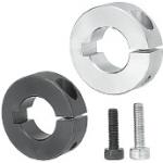
| Product name | Shaft Collars/With Key Groove/Slit |
|---|---|
| Part number | SCSKS30-15 |
* Orange colored cells in the table below indicate the part numbers used in this example.
Selection criteria
To allow even clamping of collars around shaft for increase holding power.
Available sizes
■Shaft collar (Slit type)
| Material | Surface treatment |
|---|---|
| EN 1.1191 Equiv. | Black oxide |
| Electroless nickel plating |
■Sizes and Dimensions
| I.D. (mm) | Thickness (mm) |
|---|---|
| 10 | 10 |
| 12 | 10 |
| 15 | 10 |
| 12 | |
| 15 | |
| 20 | 10 |
| 12 | |
| 15 | |
| 25 | 12 |
| 15 | |
| 30 | 15 |
Accuracy Info
■Accuracy of shaft collars
| I.D. (mm) | I.D. tolerance (mm) |
|---|---|
| 10 | +0.05 +0.01 |
| 12 | |
| 15 | |
| 20 | |
| 25 | |
| 30 |

Oil Free Bushings

| Product name | Oil Free Bushings/Copper Alloy/Thrust Type |
|---|---|
| Part number | MPGZ30-25 |
| Features | Embedded lubricant at flange allows the bearing of the radial journal load and thrust load at the same time. |
* Orange colored cells in the table below indicate the part numbers used in this example.
Selection criteria
Suitable for use in locations where both thrust and radial loads apply.
Available sizes
■Oil free bushings (Copper alloy thrust type, Standard type)
■Sizes and Dimensions
| I.D. (mm) | Length (mm) | Material |
|---|---|---|
| 6 | 10, 12 | High strength brass alloy solid lubricant embedded |
| 8 | 10, 12, 15 | |
| 10 | 10, 12, 15, 20 | |
| 12 | 10, 12, 15, 20, 25 | |
| 13 | 12, 15, 20, 25 | |
| 15 | 12, 15, 20, 25 | |
| 16 | 12, 15, 20, 25, 30 | |
| 18 | 14, 20, 25, 30, 35 | |
| 20 | 14, 20, 25, 30, 35, 40 | |
| 25 | 14, 20, 25, 30, 35, 40 | |
| 30 | 20, 25, 30, 35, 40 | |
| 35 | 20, 25, 30, 35, 40 | |
| 40 | 25, 30, 35, 40, 45, 50 | |
| 50 | 30, 35, 40, 45, 50, 55, 60 |
Accuracy Info
■Accuracy of oil free bushing
| I.D. (mm) | I.D. tolerance (mm) |
|---|---|
| 6 | +0.032 +0.020 |
| 8 | +0.040 +0.025 |
| 10 | |
| 12 | +0.050 +0.032 |
| 13 | |
| 15 | |
| 16 | |
| 18 | |
| 20 | +0.061 +0.040 |
| 25 | |
| 30 | |
| 35 | +0.075 +0.050 |
| 40 | |
| 50 |
Performance info.
■Allowable properties of oil free bushing (Reference values)
| Periodical lubrication | No lubrication | |
|---|---|---|
| Max. allowable load | 29N/mm² | |
| Max. allowable speed | 1.00m/s | 0.5m/s |
| Max. allowable PV value | 3.25Nmm² ・ m/s | 1.65Nmm² ・ m/s |


-

-
 Terms of use of CAD data and simplified drawing data
- These terms and conditions (hereinafter referred to as “the Terms") set forth the conditions for downloading CAD data and simplified drawing data provided by MISUMI Corporation (hereinafter referred to as "MISUMI") via www.misumi-europe.com operated by MISUMI Europa GmbH(hereinafter referred to as the "Website"). By downloading CAD data and simplified drawing data posted on the Website (hereafter referred to as “Data”), customers are deemed to have agreed to these Terms.
- 1. Purpose of Use
-
MISUMI offers the following:
1)CAD data found on the Website (3D CAD data, 3D Intermediate data and 2D CAD data) for the purpose of informing customers of the characteristics of the products offered by MISUMI or a manufacturer affiliated with MISUMI for use in their designs.
2)Simplified drawing data (in PDF format) for the purpose of checking the specifications of products. - 2. Characteristics of Data
- There may be a discrepancy in certain characteristics of products (for example: tolerance, surface roughness, chamfer, etc.) between the Data and the actual product. Furthermore, for the purpose of reducing the file size of the Data, some information such as oil groove shapes, threads, or spring shapes, may be removed from the Data.
- 3. Disclaimer
- MISUMI carefully creates the Data but makes no warranty as to the quality, accuracy, functionality, safety, reliability, etc., of the Data. MISUMI may at any time, and with no prior notice to customers, revise or delete Data. MISUMI assumes no responsibility for any damage or loss resulting from any revision or deletion of the Data, or any errors in said data. Customers are solely responsible for all aspects of their own designs, including those made using the Data. MISUMI may provide customers with design example data on the Website, but the quality, accuracy, functionality, safety, reliability, etc., of such data are not guaranteed. MISUMI may, at any time, and in its sole discretion, request that the customer cease its use of or destroy the Data in its possession. MISUMI may request the customer provide MISUMI documentation of such destruction.
- 4.Prohibited Acts
-
Customers or users of the Data, are prohibited from the following acts regarding the Data, in whole or in part:
(1)Requesting quotations or placing orders for products with third parties other than those authorized by MISUMI or its affiliates;
(2)Receiving quotations or orders for products from third parties by providing the Data to a third party or using the Data in their own business;
(3)Displaying links to the Website related to the Data on their own websites, etc., without consent of MISUMI or its affiliates;
(4)Using or reproducing the Data beyond the scope of the above-stated Purpose of Use;
(5)Modifying, altering, tampering with, translating, or adapting the Data;
(6)Selling, transferring, lending, sublicensing, or providing the Data to third parties in any way without consent of MISUMI or its affiliates;
(7)Altering the content, reverse engineering, decompiling, disassembling, or analyzing the Data;
(8)Publicly disclosing or exhibiting the Data without consent of MISUMI or its affiliates;
(9)Using the Data for the purpose of providing products and services identical or similar to those of MISUMI or its affiliates;
(10)Performing acts that interfere with the proper functioning of this Website, such as acquiring Data in bulk. - 5. Copyright
-
All title and copyright in and to any information contained in the Data are owned by MISUMI or the relevant manufacturer affiliated with MISUMI and are protected by applicable copyright laws and international treaties. By downloading Data, the customer acquires no ownership rights of any kind in the intellectual property contained within. Without prior approval from MISUMI, no part of the Data may be utilized (reproduced, modified, reverse-engineered, uploaded, presented, sent, distributed, licensed, sold, or published) for any purpose other than that mentioned above.
In the event Data is found to have been to be used for any purpose other than that mentioned above or against any applicable laws or the Terms, MISUMI may pursue any legal remedy available to it, which may result in forbidding the offending user from using the Data or accessing the Website. - 6. Third-Party Data
- MISUMI offers some Data provided by third parties. Such Data may be subject to separate terms and conditions, in addition to these terms. MISUMI makes no guarantee or warranty regarding Data from third parties.
- 7. Export Control
- Customers shall comply with all applicable laws and regulations regarding the export of the Data.
- 8. Amendments to the Terms
- MISUMI may, at any time, and in its sole discretion, modify these terms and conditions; any such modification will be effective immediately.
- 9. Severability
- If any term or provision of these Terms is invalid, illegal, or unenforceable in any jurisdiction, such invalidity, illegality, or unenforceability shall not affect any other term or provision of these Terms or invalidate or render unenforceable such term or provision in any other jurisdiction. Section 139 BGB (German Civil Code) shall not apply.
- 10.Miscellaneous
-
In the event that Customers violate the Terms, MISUMI and/or MISUMI Europa GmbH shall be entitled to claim the damages and expenses (including attorney's fees) incurred by such violation against the Customers.
These Terms and any disputes arising in connection therewith shall be exclusively governed by and construed in accordance with the laws of the Federal Republic of Germany, without regard to its conflicts of law principles. The courts located in Frankfurt am Main/Germany shall have exclusive jurisdiction to adjudicate any dispute arising in connection with these Terms. By downloading the Data, you agree to submit to the exclusive and personal jurisdiction of the courts located in Frankfurt am Main/Germany. - Revised: September 21, 2025
CAD Data Download (Unit Assembly)
CAD Data Download: File Format
Cautions on the CAD data
-
Assembly data shows the assembly drawings in the concept design phase. The sole purpose of the data is to explain the structure and functionality of the assembly and is not considered nor to be used as a final design.
You will need to edit the Data so that it meets your specific design conditions. -
The CAD data unit assembly consists of sub-assemblies.
Each sub-assembly unit can be used as it is or can be edited. - The Data for fabricated parts is based on easy-to-edit dimensions and shapes in sketches and histories.
- The Data including the third-part components are made by the Company.
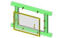
* The part in the frame is a sub-assembly unit.
-

- * Unit assembly CAD data consists of some sub-assemblies.
Each sub-assembly unit can be used as it is or can be edited.
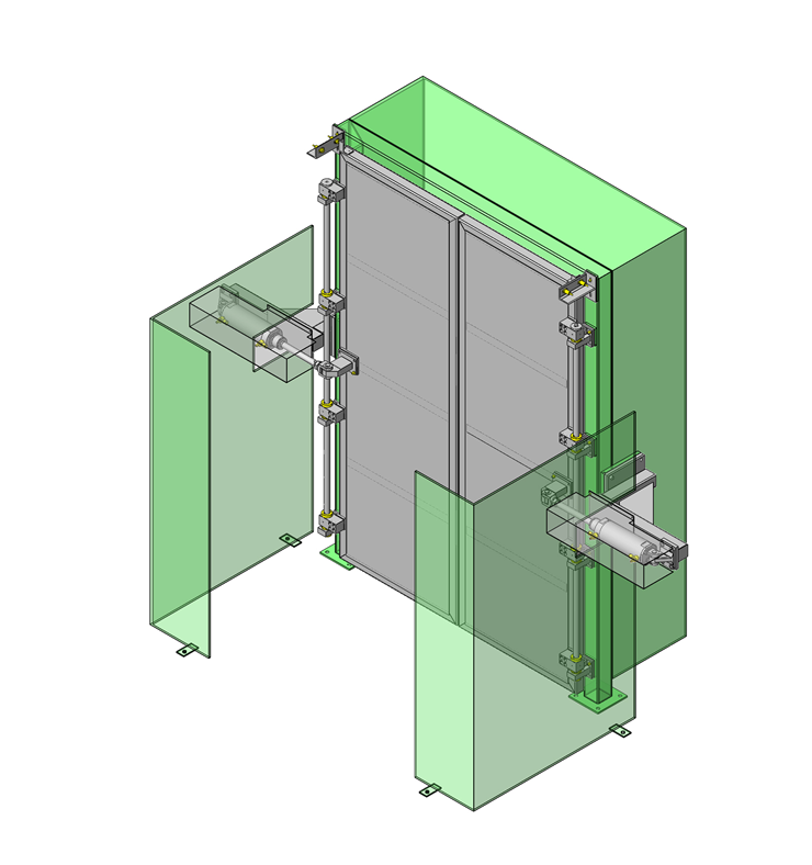
Application Overview
Purpose
- Automated door with remote operation control center.
Points for use
- Safety countermeasures such as safety fencing and remote door operation will be taken.
- Door open/close confirmation sensor is mounted above the door.
- The double door structure is operated by cylinders mounted on each side. Door swing angle is 90°.
Target workpiece
- Door size to accommodate people and material flow with sufficient clearance.
- External dims.: Up to W1800 x H2400mm can be loaded.
Design Specifications
Operating Conditions or Design Requirements
- A cylinder push/pull operates the door approx. 90° each side.
- External dimensions: W3086 x H2530 x D610mm
Selection Criteria for Main Components
- Cylinder
- Select a size needed to open / close the door.
- Thrust bushings
- Thrust bushings that can support the entire weight of the door.
Design Evaluation
Verification of main components
- Verify that the cylinder has sufficient force to open / close the door.
- Cylinder
- Operating Conditions
F = 900N - door weight
d = 30mm - shaft dia.
µ = 0.5 -friction of coefficient (shaft - oil free bushing)
L = 100mm - shortest distance from shaft to cylinder - Suppose the force to pull the door is P[N],
F x µ x (d / 2) = L x P
900 x 0.5 x 15 = 100 x P
P = 67.5N . . . (1) - Determine cylinder output thrust (Fc)
Fc = η x P x d
η = 0.5, Load factor
P = 0.4MPa - Operating pressure
d - selected tube I.D. cross section
Fc = 0.5 x 0.4MPa x π / 4 x (100² - 30²)mm²
Fc = 1429N > 67.5N (= From (1))
- Operating Conditions
- Thrust bushing
- Surface pressure applied per thrust bushing = (90kg x 9.8 / 4places) / (π / 4 x 50² -π / 4 x 30²) = 0.2N/mm² < 34.5N/mm²
(For surface pressure selected safety factor is 10)
- Surface pressure applied per thrust bushing = (90kg x 9.8 / 4places) / (π / 4 x 50² -π / 4 x 30²) = 0.2N/mm² < 34.5N/mm²
Other Design Consideration
- Positions of fixed side and door side brackets are adjusted with shims for smooth operation.
- Metal washers supported by the thrust bushings have no constraints in axial direction, and the rotational forces are uniformly transmitted to the bushings.
Explore Similar Application Examples
Page
-
/
-


Payment Method


On-Demand Manufacturing
Certificates


Copyright © MISUMI Corporation All Rights Reserved.