
- inCAD Library Home
- > No.000180 Mechanism to Check Part Condition
No.000180 Mechanism to Check Part Condition
14
Sensor position adjustments using a spring hinge.
Related Category


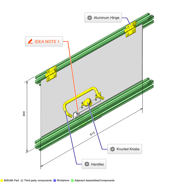
Knurled Knobs

| Product name | Knurled Knobs/Drop-Proof |
|---|---|
| Part number | NKOSD8-20 |
Selection criteria
Select Drop-proof type to prevent losing knobs when the door opens
Available sizes
■Knurled Knobs - Drop-Proof
| Material | Surface Treatment |
|---|---|
| EN 1.0711 Equiv. | Buff Polished + Chrome Plating |
| EN 1.4305 Equiv. | Brushed Finish |
■Sizes and Dimensions
| Thread | Knob | Shaft Part under Head | Stepped Shaft Part | Mounting Height | Length under head | ||||
|---|---|---|---|---|---|---|---|---|---|
| DIA. (Coarse) | Length | O.D. | Thickness | Diameter | Length | Diameter | Length | ||
| M3 | 4 | Ø12 | 2.5 | Ø6 | 6 | Ø5 | 2 | 7.5 | 10 |
| M4 | 5 | Ø16 | 3.5 | Ø8 | 5 | Ø6 | 3 | 9.5 | 10 |
| 10 | 15 | ||||||||
| M5 | 6 | Ø20 | 4 | Ø10 | 4 | Ø7.5 | 3.8 | 11.5 | 10 |
| 9 | 15 | ||||||||
| 14 | 20 | ||||||||
| M6 | 8 | Ø24 | 5 | Ø12 | 7 | Ø10 | 4.5 | 15 | 15 |
| 12 | 20 | ||||||||
| 22 | 30 | ||||||||
| M8 | 10 | Ø30 | 6 | Ø16 | 10 | Ø12 | 6 | 18 | 20 |
| 20 | 30 | ||||||||

Handles

| Product name | Handles/Offset |
|---|---|
| Part number | UHFNEA160 |
| Features | Round Bar Pull Handles - Offset |
Selection criteria
Suitable as an economical way to open and close the door.
Available sizes
■Handles - Offset
| Material | Surface Treatment |
|---|---|
| EN 1.0038 Equiv. | Chrome Plating |
| EN 1.4301 Equiv. | Buffing |
| Aluminum Alloy | |
| Anodize (Clear) | |
| Electrostatic Paint (Mat Black) |
■Sizes and Dimensions
| Rod Dia. | Overall Length | Mounting Pitch | Mounting Screw Hole | Overall Height | Overall Width | Allowable Load (N) |
|---|---|---|---|---|---|---|
| Ø10 | 58 | 48 | M5 (Coarse) Depth 13 | 47 | 40 | 2000 |
| 76 | 66 | |||||
| 98 | 88 | |||||
| 110 | 100 | |||||
| 120 | 110 | |||||
| 130 | 120 | |||||
| 135 | 125 | |||||
| 170 | 160 |

Aluminum Hinge
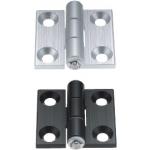
| Product name | Aluminum Hinges |
|---|---|
| Part number | HHPBSN6 |
Selection criteria
Suitable to open and close the mechanism.
Available sizes
■Aluminum Hinge
| Material | Surface Treatment |
|---|---|
| EN 1.4301 Equiv. | Gloss Tumble Polish |
■Sizes and Dimensions
| Length | Applicable Mounting Screw Dia. | Holes on One Side | Overall Width | Plate Thickness |
|---|---|---|---|---|
| 20 | - | - | 14 | 0.5 |
| 25 | M3 | 2 | 32 | 1.2 |
| 38 | 32 | 1.5 | ||
| 51 | 38 | 1.5 |
Performance info.
■Spring Load of Spring Hinges
| Length | Spring Load (kgf) |
|---|---|
| 20 | 0.38 |
| 25 | 0.4 |
| 38 | 1 |
| 51 | 0.68 |
*Spring load is a value at (A) with the hinge plates folded at 270° as shown in the figure.
Only for Length 20, the value is measured at a 180° angle position (B).
Do not bend Length 20 beyond 180° angle position (B).
Small wire diameter spring may cause problems.

-
 Terms of use of CAD data and simplified drawing data
- These terms and conditions (hereinafter referred to as “the Terms") set forth the conditions for downloading CAD data and simplified drawing data provided by MISUMI Corporation (hereinafter referred to as "MISUMI") via www.misumi-europe.com operated by MISUMI Europa GmbH(hereinafter referred to as the "Website"). By downloading CAD data and simplified drawing data posted on the Website (hereafter referred to as “Data”), customers are deemed to have agreed to these Terms.
- 1. Purpose of Use
-
MISUMI offers the following:
1)CAD data found on the Website (3D CAD data, 3D Intermediate data and 2D CAD data) for the purpose of informing customers of the characteristics of the products offered by MISUMI or a manufacturer affiliated with MISUMI for use in their designs.
2)Simplified drawing data (in PDF format) for the purpose of checking the specifications of products. - 2. Characteristics of Data
- There may be a discrepancy in certain characteristics of products (for example: tolerance, surface roughness, chamfer, etc.) between the Data and the actual product. Furthermore, for the purpose of reducing the file size of the Data, some information such as oil groove shapes, threads, or spring shapes, may be removed from the Data.
- 3. Disclaimer
- MISUMI carefully creates the Data but makes no warranty as to the quality, accuracy, functionality, safety, reliability, etc., of the Data. MISUMI may at any time, and with no prior notice to customers, revise or delete Data. MISUMI assumes no responsibility for any damage or loss resulting from any revision or deletion of the Data, or any errors in said data. Customers are solely responsible for all aspects of their own designs, including those made using the Data. MISUMI may provide customers with design example data on the Website, but the quality, accuracy, functionality, safety, reliability, etc., of such data are not guaranteed. MISUMI may, at any time, and in its sole discretion, request that the customer cease its use of or destroy the Data in its possession. MISUMI may request the customer provide MISUMI documentation of such destruction.
- 4.Prohibited Acts
-
Customers or users of the Data, are prohibited from the following acts regarding the Data, in whole or in part:
(1)Requesting quotations or placing orders for products with third parties other than those authorized by MISUMI or its affiliates;
(2)Receiving quotations or orders for products from third parties by providing the Data to a third party or using the Data in their own business;
(3)Displaying links to the Website related to the Data on their own websites, etc., without consent of MISUMI or its affiliates;
(4)Using or reproducing the Data beyond the scope of the above-stated Purpose of Use;
(5)Modifying, altering, tampering with, translating, or adapting the Data;
(6)Selling, transferring, lending, sublicensing, or providing the Data to third parties in any way without consent of MISUMI or its affiliates;
(7)Altering the content, reverse engineering, decompiling, disassembling, or analyzing the Data;
(8)Publicly disclosing or exhibiting the Data without consent of MISUMI or its affiliates;
(9)Using the Data for the purpose of providing products and services identical or similar to those of MISUMI or its affiliates;
(10)Performing acts that interfere with the proper functioning of this Website, such as acquiring Data in bulk. - 5. Copyright
-
All title and copyright in and to any information contained in the Data are owned by MISUMI or the relevant manufacturer affiliated with MISUMI and are protected by applicable copyright laws and international treaties. By downloading Data, the customer acquires no ownership rights of any kind in the intellectual property contained within. Without prior approval from MISUMI, no part of the Data may be utilized (reproduced, modified, reverse-engineered, uploaded, presented, sent, distributed, licensed, sold, or published) for any purpose other than that mentioned above.
In the event Data is found to have been to be used for any purpose other than that mentioned above or against any applicable laws or the Terms, MISUMI may pursue any legal remedy available to it, which may result in forbidding the offending user from using the Data or accessing the Website. - 6. Third-Party Data
- MISUMI offers some Data provided by third parties. Such Data may be subject to separate terms and conditions, in addition to these terms. MISUMI makes no guarantee or warranty regarding Data from third parties.
- 7. Export Control
- Customers shall comply with all applicable laws and regulations regarding the export of the Data.
- 8. Amendments to the Terms
- MISUMI may, at any time, and in its sole discretion, modify these terms and conditions; any such modification will be effective immediately.
- 9. Severability
- If any term or provision of these Terms is invalid, illegal, or unenforceable in any jurisdiction, such invalidity, illegality, or unenforceability shall not affect any other term or provision of these Terms or invalidate or render unenforceable such term or provision in any other jurisdiction. Section 139 BGB (German Civil Code) shall not apply.
- 10.Miscellaneous
-
In the event that Customers violate the Terms, MISUMI and/or MISUMI Europa GmbH shall be entitled to claim the damages and expenses (including attorney's fees) incurred by such violation against the Customers.
These Terms and any disputes arising in connection therewith shall be exclusively governed by and construed in accordance with the laws of the Federal Republic of Germany, without regard to its conflicts of law principles. The courts located in Frankfurt am Main/Germany shall have exclusive jurisdiction to adjudicate any dispute arising in connection with these Terms. By downloading the Data, you agree to submit to the exclusive and personal jurisdiction of the courts located in Frankfurt am Main/Germany. - Revised: September 21, 2025
CAD Data Download (Unit Assembly)
CAD Data Download: File Format
Cautions on the CAD data
-
Assembly data shows the assembly drawings in the concept design phase. The sole purpose of the data is to explain the structure and functionality of the assembly and is not considered nor to be used as a final design.
You will need to edit the Data so that it meets your specific design conditions. -
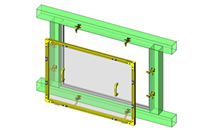
The CAD data unit assembly consists of sub-assemblies.
Each sub-assembly unit can be used as it is or can be edited. - The Data for fabricated parts is based on easy-to-edit dimensions and shapes in sketches and histories.
- The Data including the third-part components are made by the Company.
* The part in the frame is a sub-assembly unit.
-

- * Unit assembly CAD data consists of some sub-assemblies.
Each sub-assembly unit can be used as it is or can be edited.
Application Overview
Purpose
- Purpose
- Prevents failure when closing or affixing the maintenance door.
- Operation
- After closing the door, fix the bracket connected to the door with the spring hinge using the knurled knob. At this point, the bracket shields the sensor from light. By removing the knurled knob, the bracket and knob are flipped up, tripping the check sensor.
Points for use
- Manually operated.
Target workpiece
- Doors that require interlock.
Design Specifications
Selection Criteria for Main Components
- Spring hinges that can be flipped up against the weight of the knob.
Design Evaluation
Verification of main components
- The spring hinges are verified based on the load moment, to see whether the dog moves away from the sensor.
-
- Conditional Value:
Total mass of dog and knob: m = 0.10kg
Horizontal distance between hinge shaft and center of gravity of dog and knob: a 20.0mm
Load of hinge spring: k = 0.40kgf
Hinge spring load definition angle: θ = 270°
Hinge spring load position: b = 16mm
Number of hinge springs: n = 2pieces
Hinge spring load in free condition: k0 = 0.10kgf
Hinge spring angle in free condition: θ0=90°
Target hinge angle: θ1 = 225°
Gravitational acceleration: g = 9.8m/s²
Hinge spring load at target angle: k1 = {(k - k0)/(θ - θ0)} x θ1 = {(0.4 - 0.1)/(270 - 90)} x 225 = 0.375kgf
Total hinge spring load at target angle: k1' = k1 x n = 0.375 x 2 = 0.75kgf
Moment by dog and knob: M1=m x g x a, hence, M1 = 0.1 x 9.8 x 20 = 2.0kgf・mm
Moment by hinge: M2 = k1' x b, hence, M2 = 0.75 x 16 = 12.0kgf・mm
From M1 < M2, the angle of the hinge at an unfixed state satisfies the target angle θ1 at which the dog moves away from the sensor.
- Conditional Value:
Other Design Consideration
- The mechanism is designed so that when flipped up, the spring hinge flips the total weight of the dog away from the sensor.
- The photomicrosensor should be set to turn on when shielded from light, and the interlock should be applied when the sensor turns off due to the door being open or failure of the sensor.
Explore Similar Application Examples


Payment Method


On-Demand Manufacturing
Certificates


Copyright © MISUMI Corporation All Rights Reserved.