Clamp Cylinder Magnetic Field Resistant Auto Switch, CKG1/CKP1/CK1/CKGA/CKPA Series (CK1A50TF-50YZ)
Product Details:
Manufacturer part number: CK1A50TF-50YZ
Brand: SMC
Price: 183.76 €
Delivery time: 26 Days
Technical Data:
Cylinder Diameter: 50 Ø
Stroke: 50 mm
Rod Tip Shape: [Others] Others
Body options: -
Operating Temperature Range: -10~70 ℃
(i)Remark
- Refer to the catalog for details on product specifications.
- The products shown in the image are representative. CAD data is not supported for some model numbers.
Part Number
Once your search is narrowed to one product,
the corresponding part number is displayed here.
CK1A50TF-50YZ
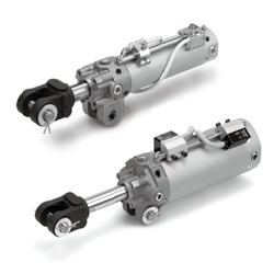
Details of Clamp Cylinder Magnetic Field Resistant Auto Switch (Rod Mount Type) CKG1/CKP1 Series
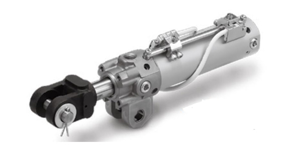
CKG1 product image
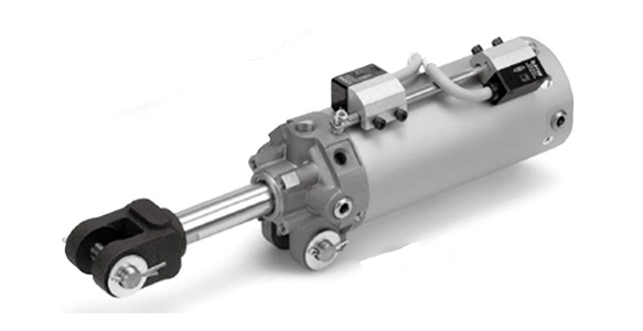
CKP1 product image
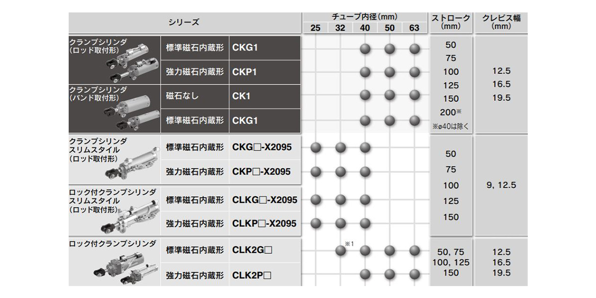
Image of CK1 series variation table
- * 1Clevis width is 12 mm.
Specifications of Clamp Cylinder Magnetic Field Resistant Auto Switch (Rod Mount Type) CKG1/CKP1 Series
Part number display method (Magnetic field resistant auto switch)
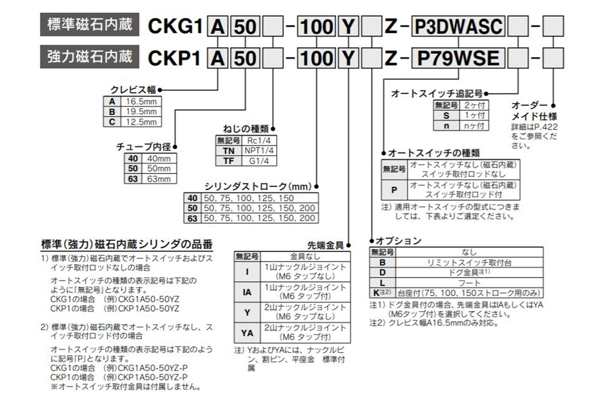
Magnetic field resistant auto switch, part number example
Part number display method (Standard auto switch)

Standard auto switch part number example
Individual made-to-order specifications Part number example
Made to Order Specifications

Made-to-order specifications table image
- * There is no setting for the CKP1 series.
Standard auto switch
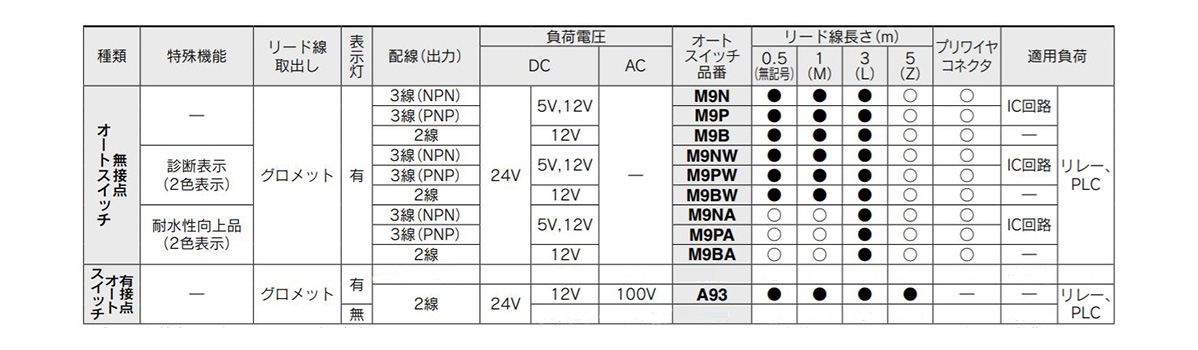
Image of standard auto switch selection table
- * The standard auto switch cannot be used in a strong magnetic field environment.
- * 〇The non-contact auto switches marked with are made-to-order.
- * The auto switch and mounting bracket are shipped together (not assembled).
Specifications
| Tube Internal Diameter (mm) | 40 | 50 | 63 |
|---|---|---|---|
| Fluid | Air | ||
| Proof Pressure | 1.5 MPa | ||
| Maximum operating pressure | 1.0 MPa | ||
| Minimum operating pressure | 0.05 MPa | ||
| Ambient and fluid temperature | -10°C to +60°C | ||
| Piston Speed | 50 to 500 mm/s | ||
| Cushioning | Unclamp side (Head Side): With Air Cushion | ||
| Speed controller | Double-sided | ||
| Lubrication | Not required | ||
| Stroke Length Tolerance | +1.0 | ||
| 0 | |||
| Mounting support type *) | Double Clevis | ||
- * *) Clevis pin, cotter pin, and plain washer are included as standard.
Clevis width
| Clevis width | 16.5 mm | CKG1A/CKP1A |
|---|---|---|
| 19.5 mm | CKG1B/CKP1B | |
| 12.5 mm | CKG1C/CKP1C |
Standard Stroke Table
| Tube Internal Diameter (mm) | Standard Stroke (mm) |
|---|---|
| 40 | 50,75,100,125,150 |
| 50,63 | 50,75,100,125,150,200 |
Tip fitting / option
| Model code | Part Name | Part No. | |||
|---|---|---|---|---|---|
| CKG1A/CKP1A | CKG1B/CKP1B | CKG1C/CKP1C | |||
| I | Single knuckle joint | M6 no tapping | CKB-I04 | ||
| IA | M6 tapped | CKB-IA04 | |||
| Y | U-Shaped Knuckle Joint (Knuckle pin, cotter pin Plain washer included as standard) | M6 no tapping | CKA-Y04 | CKB-Y04 | CKC-Y04 |
| YA | M6 tapped | CKA-YA04 | CKB-YA04 | CKC-YA04 | |
Weight Table (* The basic weight is the 0 stroke weight including the switch mounting rod. )
(Unit: kg)
| Tube Internal Diameter (mm) | 40 | 50 | 63 | |
|---|---|---|---|---|
| CKG1□ cylinder | Basic weight | 0.70 | 0.92 | 1.12 |
| Extra weight per 25 strokes | 0.11 | 0.12 | 0.14 | |
| CKP1□ cylinder | Basic weight | 0.72 | 0.98 | 1.28 |
| Extra weight per 25 strokes | 0.11 | 0.12 | 0.14 | |
| Single knuckle joint | 0.20 | |||
| U-Shaped Knuckle Joint (Knuckle pin, cotter pin, plain washer included as standard) | 0.34 | |||
Calculation
Example) CKG1□50-100YZ-P
- Basic weight: 0.92 kg (ø50 [diameter: 50 mm])
- Extra weight: 0.12/25 stroke
- Cylinder stroke: 100 stroke
- Double knuckle joint: 0.34 (Y)
0.92 + 0.12 × 100/25 + 0.34 = 1.74 kg
Theoretical Output Table
(Unit: N)
| Tube inner diameter (mm) | Rod Diameter (mm) | Operation Direction | Piston Area (mm^2) | Operating Pressure (MPa) | |||
|---|---|---|---|---|---|---|---|
| 0.3 | 0.4 | 0.5 | 0.6 | ||||
| 40 | 20 | OUT | 1,260 | 378 | 504 | 630 | 756 |
| IN | 943 | 283 | 377 | 472 | 566 | ||
| 50 | 20 | OUT | 1,960 | 588 | 784 | 980 | 1,180 |
| IN | 1,650 | 495 | 660 | 825 | 990 | ||
| 63 | 20 | OUT | 3,120 | 934 | 1,250 | 1,560 | 1,870 |
| IN | 2,800 | 840 | 1,120 | 1,400 | 1,680 | ||
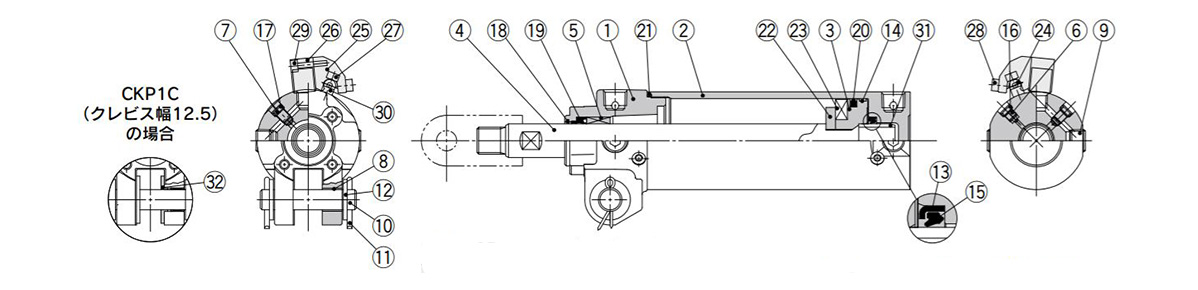
Structural drawing (CKG1 40, 50, 63 rod mount type)
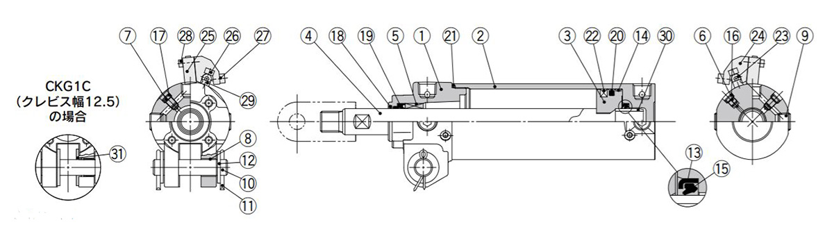
Structural drawing of CKG1 40, 50, 63 rod mounting type
Components
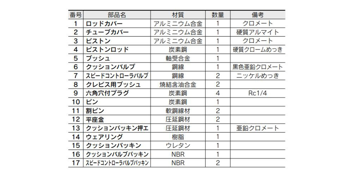
Image for components parts table (1 to 17) of CKG1 40, 50, 63 rod mount type
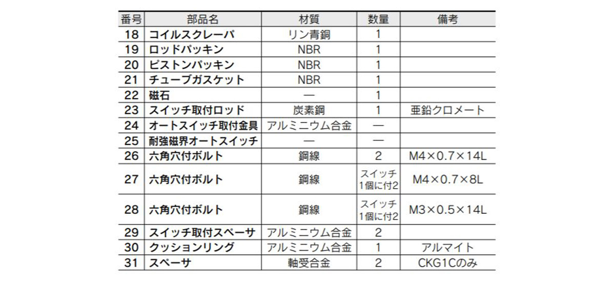
Image for structural parts table (18 to 31) of CKG1 40, 50, 63 rod mounting type
Structural drawing (CKP1 40, 50, 63 rod mount type)
Structural drawing of CKP1 40, 50, 63 rod mounting type
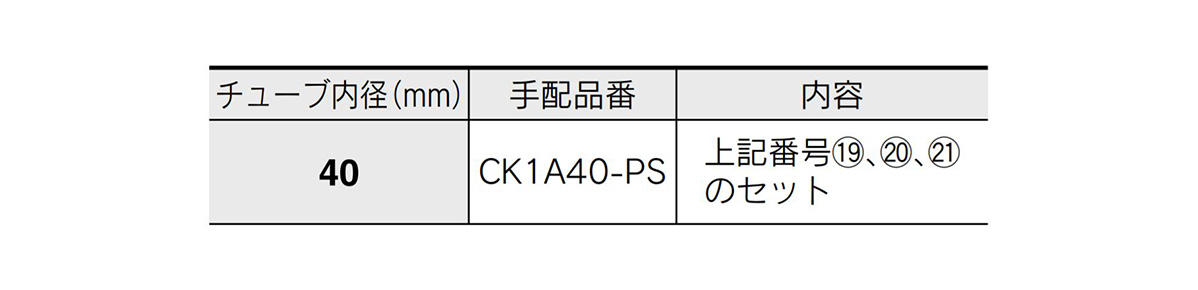
Replacement Parts / Seal Kit

Detailed image of replacement parts / seal kit
*1) The seal kit is the same for CKG1□/CKP1□.
*2) The seal kit does not come with a grease pack, so order it separately. Grease part number: GR-S-010 (Common to all sizes)
*3) When it is ø50 (diameter: 50 mm) or more, it is impossible to disassemble because it is tightened with a large tightening torque. Please contact the manufacturer if disassembly is required.
Components
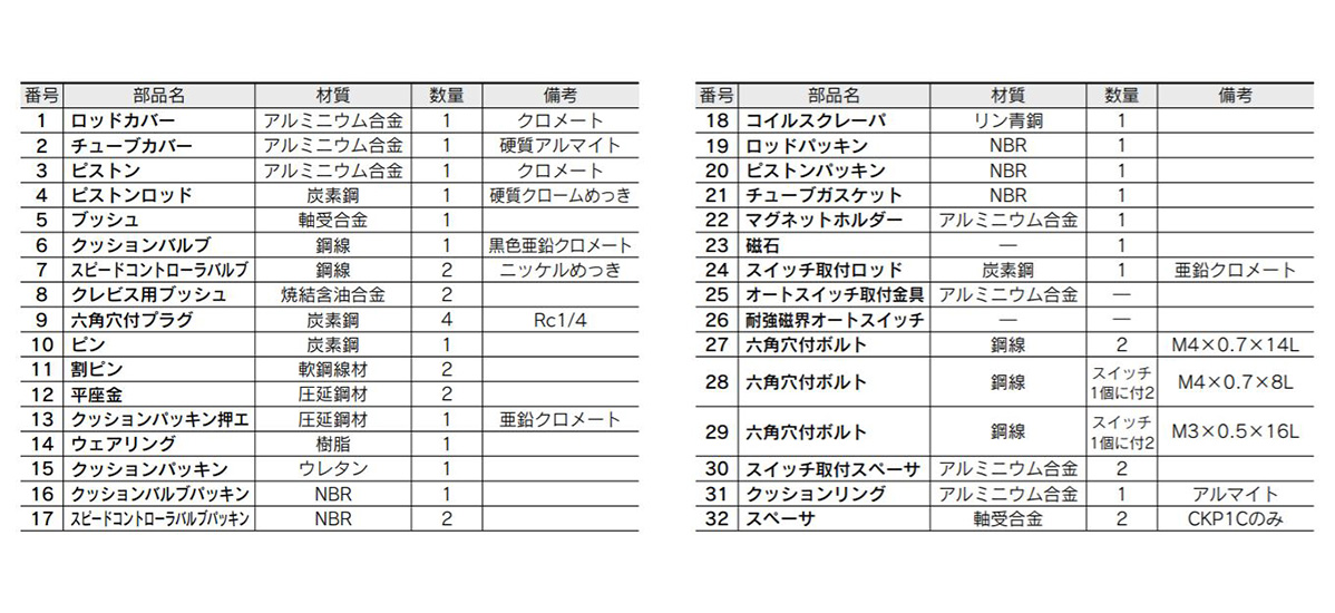
Image for structural parts table of CKP1 40, 50, 63 rod mounting type
Dimensions of Clamp Cylinder Magnetic Field Resistant Auto Switch (Rod Mount Type) CKG1/CKP1 Series
CKG1□40, 50, 63 rod mount type
(Units: mm)
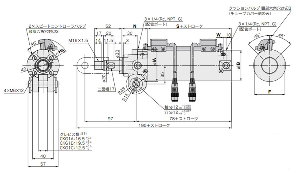
Dimensional drawing of CKG1□40, 50, 63 rod mounting type
(Units: mm)
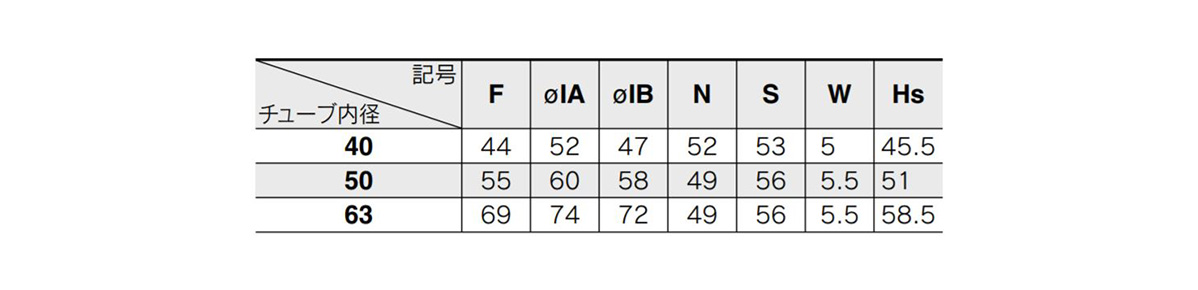
Image of dimensions table for CKG1□40, 50, 63 rod mount type
CKP1□40, 50, 63 rod mount type
(Units: mm)
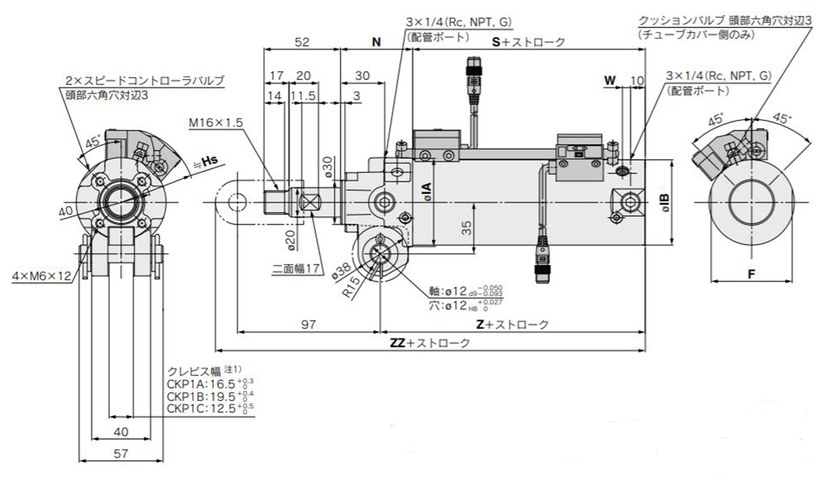
Dimensional drawing of CKG1□40, 50, 63 rod mounting type
(Units: mm)
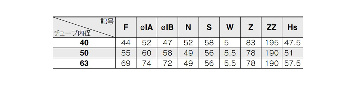
Dimensions table of CKP1□40, 50, 63 rod mount type
*1) Indicates the location of the clevis minimum width (tube side).
Details of Clamp Cylinder Magnetic Field Resistant Auto Switch (Band Mount Type) CK1/CKG1 Series
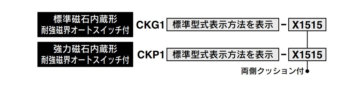
Part number display method (Magnetic field resistant auto switch)
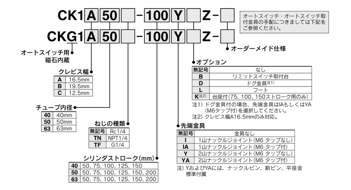
Image of display method for part numbers of the CK1/CKG1 series
Part number display method (Standard auto switch)
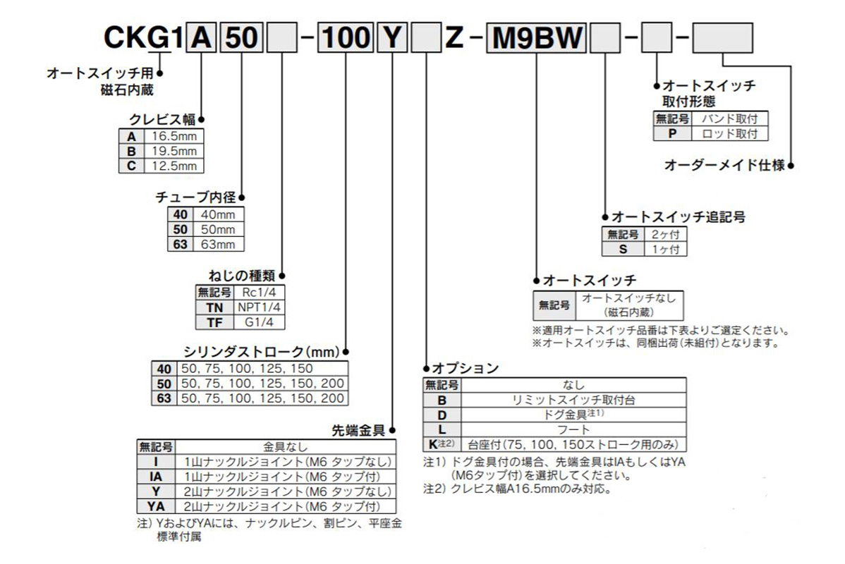
Image of display method for part numbers of the CKG1 series
Specifications
| Tube Internal Diameter (mm) | 40 | 50 | 63 |
|---|---|---|---|
| Fluid | Air | ||
| Proof Pressure | 1.5 MPa | ||
| Maximum operating pressure | 1.0 MPa | ||
| Minimum operating pressure | 0.05 MPa | ||
| Ambient and fluid temperature | Without auto switch: -10°C to +70°C With auto switch: -10°C to +60°C | ||
| Piston Speed | 50 to 500 mm/s | ||
| Cushioning | Unclamp side (Head Side): With Air Cushion | ||
| Speed controller | Double-sided | ||
| Lubrication | Not required | ||
| Stroke Length Tolerance | +1.0 | ||
| 0 | |||
| Mounting support type *) | Double Clevis | ||
* *) Clevis pin, cotter pin, and plain washer are included as standard.
Clevis width
| Clevis width | 16.5 mm | CK1A/CKG1A |
|---|---|---|
| 19.5 mm | CK1B/CKG1B | |
| 12.5 mm | CK1C/CKG1C |
Standard Stroke Table
| Tube Internal Diameter (mm) | Standard Stroke (mm) |
|---|---|
| 40 | 50,75,100,125,150 |
| 50,63 | 50,75,100,125,150,200 |
Tip fitting / option
| Model code | Part Name | Part No. | |||
|---|---|---|---|---|---|
| CK1A/CKG1A | CK1B/CKG1B | CK1C/CKG1C | |||
| I | Single knuckle joint | M6 no tapping | CKB-I04 | ||
| IA | M6 tapped | CKB-IA04 | |||
| Y | U-Shaped Knuckle Joint (Knuckle pin, cotter pin Plain washer included as standard) | M6 no tapping | CKA-Y04 | CKB-Y04 | CKC-Y04 |
| YA | M6 tapped | CKA-YA04 | CKB-YA04 | CKC-YA04 | |
Weight Table
(Unit: kg)
| Tube Internal Diameter (mm) | 40 | 50 | 63 | |
|---|---|---|---|---|
| Cylinder | Basic weight | 0.68 | 0.90 | 1.10 |
| Extra weight per 25 strokes | 0.10 | 0.11 | 0.13 | |
| Single knuckle joint | 0.20 | |||
| U-Shaped Knuckle Joint (Knuckle pin, cotter pin, plain washer included as standard) | 0.34 | |||
Calculation
Example) CKG1□50-100YZ
- Basic weight: 0.92 kg (ø50 [diameter: 50 mm])
- Extra weight: 0.12/25 stroke
- Cylinder stroke: 100 stroke
- Double knuckle joint: 0.34 (Y)
0.90 + 0.11 × 100/25 + 0.34 = 1.68 kg
Theoretical Output Table
(Unit: N)
| Tube inner diameter (mm) | Rod Diameter (mm) | Operation Direction | Piston Area (mm^2) | Operating Pressure (MPa) | |||
|---|---|---|---|---|---|---|---|
| 0.3 | 0.4 | 0.5 | 0.6 | ||||
| 40 | 20 | OUT | 1,260 | 378 | 504 | 630 | 756 |
| IN | 943 | 283 | 377 | 472 | 566 | ||
| 50 | 20 | OUT | 1,960 | 588 | 784 | 980 | 1,180 |
| IN | 1,650 | 495 | 660 | 825 | 990 | ||
| 63 | 20 | OUT | 3,120 | 934 | 1,250 | 1,560 | 1,870 |
| IN | 2,800 | 840 | 1,120 | 1,400 | 1,680 | ||
Structural drawing (CK 1 40, 50, 63 rod mount type)
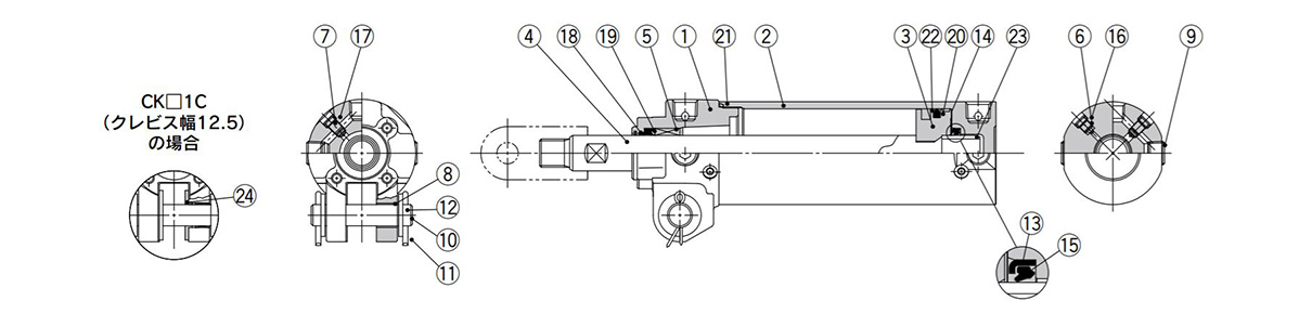
Structural drawing of CK 1 40, 50, 63, clamp mounting type
Components
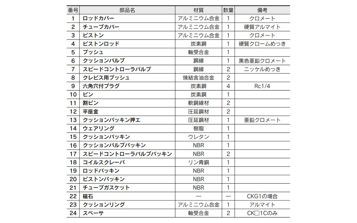
Image for components parts table of CK 1 40, 50, 63, clamp mounting type
Replacement Parts / Seal Kit
Detailed image of replacement parts / seal kit
Dimensions of CK□1□40, 50, 63, clamp mounting type
(Units: mm)
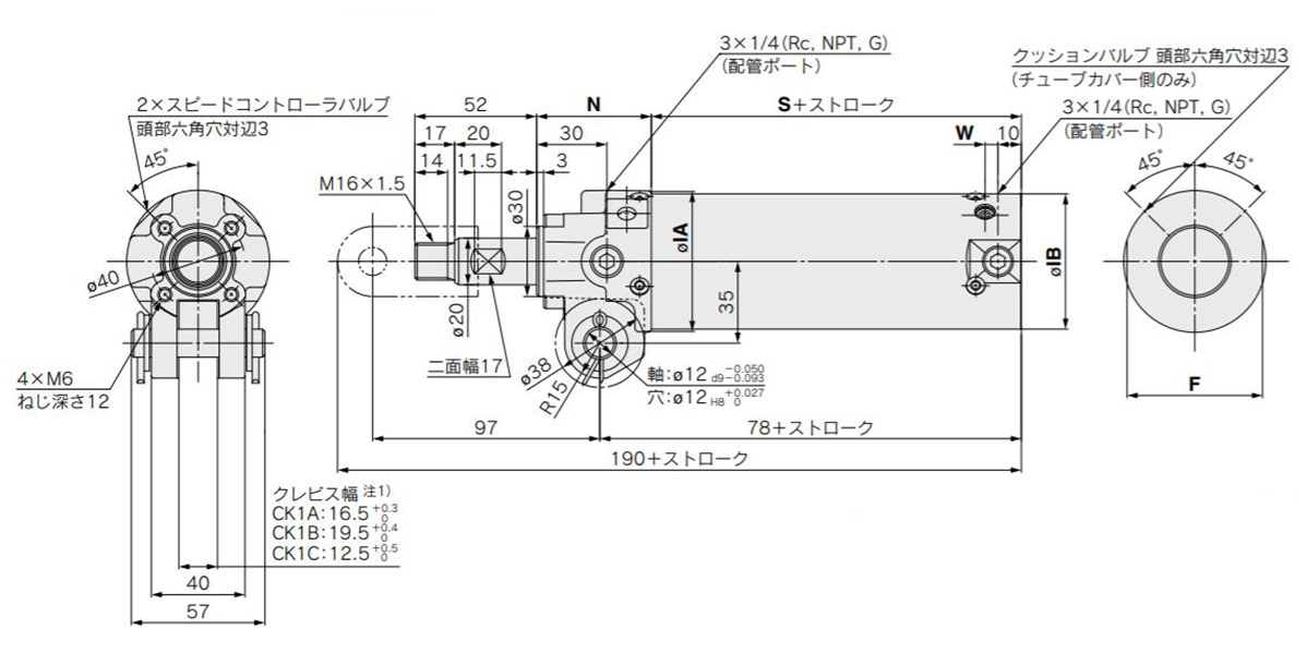
Dimensional drawing of CK□1□40, 50, 63, clamp mounting type
(Units: mm)
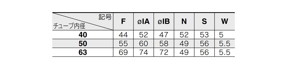
Image for dimension table of CK□1□40, 50, 63, clamp mounting type
*1) Indicates the location of the clevis minimum width (tube side).
End bracket
Single knuckle joint
(Units: mm)
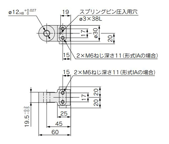
Dimensional drawing of single knuckle joint
Material: Cast iron
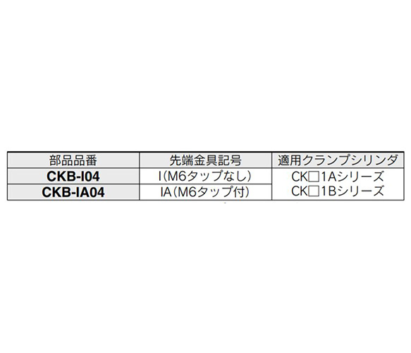
Single knuckle joint detailed table image
U-Shaped Knuckle Joint
(Units: mm)
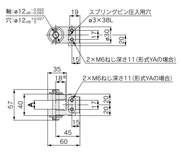
Dimensional drawing of double knuckle joint
(Units: mm)
Material: Cast iron
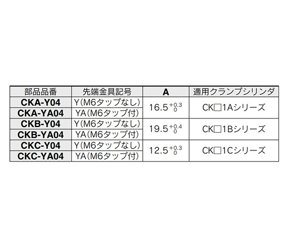
Double knuckle joint detailed table image
*1) Knuckle pin, cotter pin, plain washer, and spring pin are included as standard with the double knuckle joint.
*2) The conventional product is equivalent to the part number CKA-YA04, CKB-YA04 (rod end bracket symbol YA).
*3) * The dimensions indicated are dimensions as mounted on the piston rod.
Pin
(Units: mm)
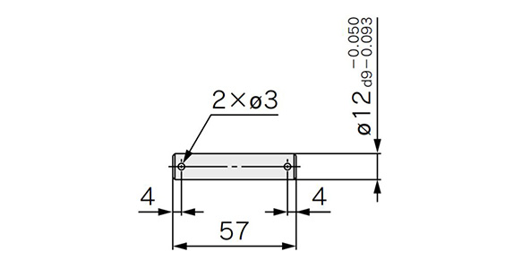
Dimensional drawing of pin
Material: carbon steel
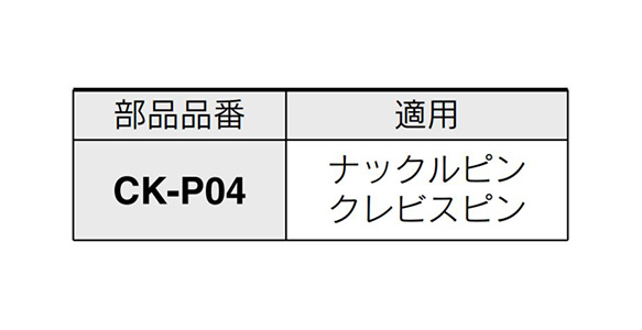
Pin detailed table image
- * *) Cotter pins and plain washers are attached to the pins as standard.
Limit switch mounting base / dog bracket
(Units: mm)
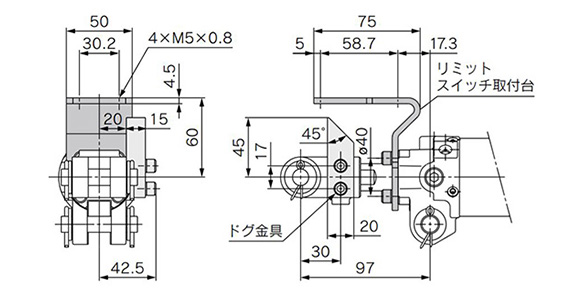
Dimensional drawing of limit switch mounting base / dog bracket
Material: Rolled steel
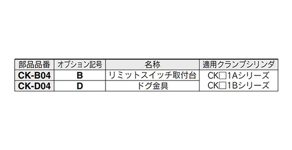
Limit switch mounting base / dog bracket detailed table image
*1) You can remove the hex socket head bolt and change the limit switch mounting base and dog bracket to any position.
*2) When the limit switch mounting base and dog bracket are ordered as parts, the mounting bolts (hex socket head bolt) and spring lock washers are attached as standard.
* When installing the dog fitting, be sure to select the M6 tapped knuckle joint (rod end fitting symbol IA or YA). It cannot be attached to the knuckle joint without M6 tap (rod end bracket symbol I or Y).
Foot
(Units: mm)
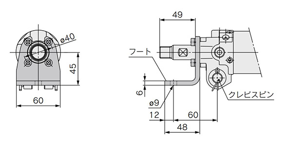
Dimensional drawing of foot
Material: Rolled steel
Foot detailed table image
*1) Mounting foot (hex socket head bolt) spring lock washer is attached to the foot as standard.
*2) Use the foot and clevis pin for mounting the cylinder. Do not install the foot by itself, as it is dangerous and may cause damage.
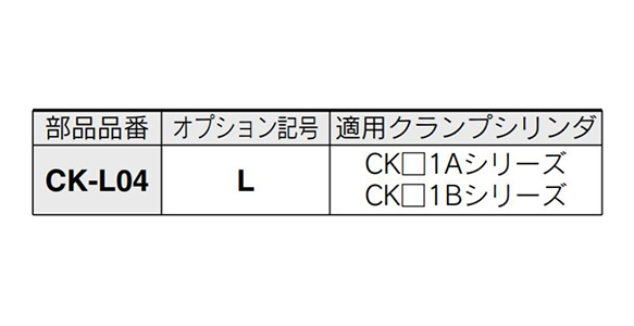
Pedestal
(Units: mm)
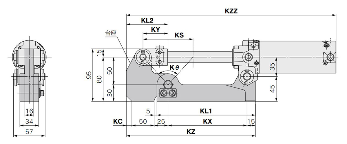
Dimensional drawing of base
Material: Rolled steel
(Units: mm)
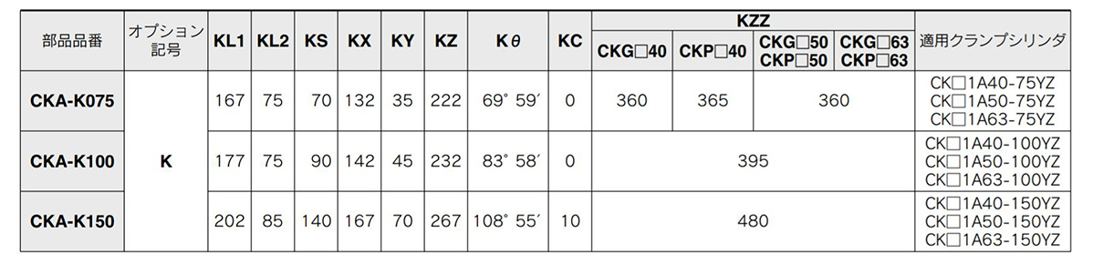
Base dimension table image
*) Only compatible with the CK□1 A series (clevis width: 16.5 mm).
Please refer to the table below for details about lead wire / connector specifications.


Part Number
|
|---|
| CK1A50TF-50YZ |
| Part Number |
Standard Unit Price
| Minimum order quantity | Volume Discount | Cylinder Diameter (Ø) | Stroke (mm) | Rod Tip Shape | Body options | Operating Temperature Range (℃) | Clamping Force (kN) | Auto Switch | Lead Wire Length (m) | Number of Switches | Specifications | Port Screw Type | Clevis width (mm) | Tip fitting | Limit switch mounting base | Metal dog bracket | Foot | Base | Switch mounting rod | Made to order specifications | Connector type | |
|---|---|---|---|---|---|---|---|---|---|---|---|---|---|---|---|---|---|---|---|---|---|---|---|---|
183.76 € | 1 | 26 Days | 50 | 50 | [Others] Others | - | -10~70 | - | Without switch | - | - | - | G1/4 | 16.5 | Double knuckle joint (M6 without tap) | None | None | None | None | - | None | - |
Loading...
Basic information
| Operation Method | Straight Advancing Stroke | Support Type | Clevis | Max. Pressure(MPa) | 1 |
|---|
This page is Clamp Cylinder Magnetic Field Resistant Auto Switch, CKG1/CKP1/CK1/CKGA/CKPA Series, part number CK1A50TF-50YZ.
You can find the detail information about specifications and dimensions on part number CK1A50TF-50YZ.
Configure
Basic Attributes
-
Body options
- No (Standard)
-
Clamping Force(kN)
-
Lead Wire Length(m)
- 0.3
- 0.5
- 0.5 (SC type)
- 0.5 (SE type)
- 3
- 5
-
Number of Switches
-
Specifications
- Powerful built-in magnet
- Standard built-in magnet
-
Switch mounting rod
- None
- Yes
-
Connector type
- M12-3/4 pin
- M12-1/4 pin
-
Type
- CK1
- CKG1
- CKGA
- CKP1
-
Cylinder Diameter(Ø)
-
Stroke(mm)
-
Rod Tip Shape
- Others
- Others
-
Auto Switch
-
Port Screw Type
- G1/4
- NPT1/4
- Rc1/4
-
Clevis width(mm)
- 12
- 12.5
- 16.5
- 19.5
- 28
-
Tip fitting
- 2 mountain knuckle joint (No Tapping)
- 2 mountain knuckle joint (Tapped)
- Double knuckle joint (M6 with tap)
- Double knuckle joint (M6 without tap)
- Single knuckle joint (M6 with tap)
- Single knuckle joint (M6 without tap)
- No bracket
-
Limit switch mounting base
- None
- Yes
-
Metal dog bracket
- None
- Yes
-
Foot
- None
- Yes
-
Base
- None
- Yes
-
Made to order specifications
- Spatter-resistant coil scraper, lube-retainer, grease for welding, piston rod: S45C
- Spatter-resistant coil scraper, lube-retainer, grease for welding, piston rod: S45C with air cushions on both sides
- Spatter-resistant coil scraper, lube-retainer, grease for welding, piston rod: SUS304
- None
- With air cushions on both sides
-
Filter by CAD data type
- 2D
- 3D
Filter by standard shipping days
-
- All
- 4 Days or Less
- 19 Days or Less
- 26 Days or Less
- 31 Days or Less
Optional Attributes
- The specifications and dimensions of some parts may not be fully covered. For exact details, refer to manufacturer catalogs .
Variation of this product
| Part Number |
|---|
| CK1A40-125YZ |
| CK1A40-125Z |
| CK1A40-150YZ |
| CK1A50TF-75YAZ |
| CK1A50TF-75YZ |
| CK1A63-100IAZ |
| Part Number | Standard Unit Price | Minimum order quantity | Volume Discount | Standard Shipping Days ? | Cylinder Diameter (Ø) | Stroke (mm) | Rod Tip Shape | Body options | Operating Temperature Range (℃) | Clamping Force (kN) | Auto Switch | Lead Wire Length (m) | Number of Switches | Specifications | Port Screw Type | Clevis width (mm) | Tip fitting | Limit switch mounting base | Metal dog bracket | Foot | Base | Switch mounting rod | Made to order specifications | Connector type |
|---|---|---|---|---|---|---|---|---|---|---|---|---|---|---|---|---|---|---|---|---|---|---|---|---|
185.98 € | 1 | 26 Days | 40 | 125 | [Others] Others | - | -10~70 | - | Without switch | - | - | - | Rc1/4 | 16.5 | Double knuckle joint (M6 without tap) | None | None | None | None | - | None | - | ||
168.39 € | 1 | 26 Days | 40 | 125 | [Others] Others | - | -10~70 | - | Without switch | - | - | - | Rc1/4 | 16.5 | No bracket | None | None | None | None | - | None | - | ||
190.44 € | 1 | 26 Days | 40 | 150 | [Others] Others | - | -10~70 | - | Without switch | - | - | - | Rc1/4 | 16.5 | Double knuckle joint (M6 without tap) | None | None | None | Yes | - | None | - | ||
189.32 € | 1 | 26 Days | 50 | 75 | [Others] Others | - | -10~70 | - | Without switch | - | - | - | G1/4 | 16.5 | Double knuckle joint (M6 with tap) | None | None | None | Yes | - | None | - | ||
189.32 € | 1 | 26 Days | 50 | 75 | [Others] Others | - | -10~70 | - | Without switch | - | - | - | G1/4 | 16.5 | Double knuckle joint (M6 without tap) | None | None | None | Yes | - | None | - | ||
245.37 € | 1 | 26 Days | 63 | 100 | [Others] Others | - | -10~70 | - | Without switch | - | - | - | Rc1/4 | 16.5 | Single knuckle joint (M6 with tap) | None | None | None | Yes | - | None | - |
Tech Support
- Technical Support
- Tel:+49 69 668173-0 / FAX:+49 69 668173-360
- Technical Inquiry
Payment Method


On-Demand Manufacturing
Certificates


Copyright © MISUMI Corporation All Rights Reserved.