Direct Operated 2 Port Solenoid Valve VX21 / 22 / 23 Series (Part Numbers - CAD Download)
[Features]
· IP65 protective enclosure
· UL94V-0 conforming flame resistance
· Low noise construction
· Piping variations
· Clearance
· Improved armature durability
(i)Remark
- Product images may be representative images. Refer to the catalog for details.
Part Number
Once your search is narrowed to one product,
the corresponding part number is displayed here.
VX210BF
Direct Operated 2 Port Solenoid Valve VX21/VX22/VX23 Series Features
| Valve Specifications | Valve Construction | Direct operated poppet | |
|---|---|---|---|
| Withstand Pressure | 2.0 MPa (resin body type: 1.5 MPa) | ||
| Body Material | Aluminum, resin, C37, Stainless steel | ||
| Seal Material*3 | NBR, FKM | ||
| Enclosure | Dustproof, water-jet-proof type (IP65)*1, *4 | ||
| Environment | Locations without corrosive or explosive gases | ||
| Coil Specifications | Rated Voltage | AC | 100 V AC, 200 V AC, 110 V AC, 230 V AC, (220 V AC, 240 V AC, 48 V AC, 24 V AC)*2 |
| DC | 24 V DC, (12 V DC)*2 | ||
| Allowable Voltage Fluctuation | ±10% of rated voltage | ||
| Allowable Leakage Voltage | AC | 5% or less of rated voltage | |
| DC | 2% or less of rated voltage | ||
| Coil Insulation Type | Class B, class H | ||
*1 Electrical entry "Faston" type terminal is IP40 compliant.
*2 Voltage inside () indicates special voltage.
*3 Refer to X332 regarding seal material / EPDM.
*4 See glossary for information on protection grades. Contact the SMC support center regarding use in locations that require water resistance.
- *Be sure to read the individual product precautions before use.
For Air Single Unit Specifications

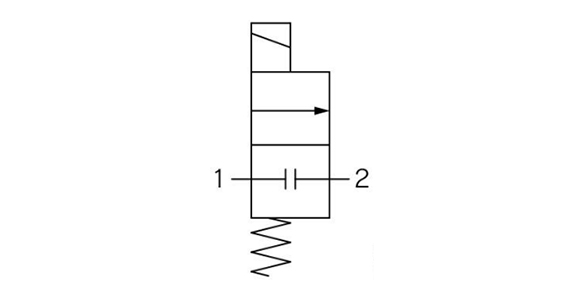
N.C. type flow passage symbol

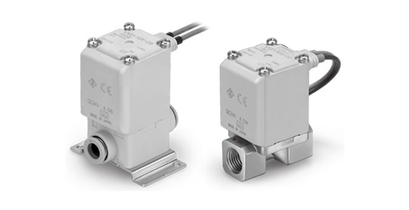
N.C. type external appearance
Aluminum Body Type
| Size | Port Size | ø(Orifice Diameter mm)*1 | Model | Flow Rate Characteristics*2 | Maximum Operating Pressure Differential MPa *4 | Maximum System Pressure MPa *4 | Weight*3 (g) | ||
|---|---|---|---|---|---|---|---|---|---|
| C [dm3/(s·bar)] | b | Cv | |||||||
| 1 | 1/8, 1/4 | 2 | VX210 | 0.63 | 0.63 | 0.23 | 1.0 | 1.0 | 220 |
| 3 | 1.05 | 0.68 | 0.41 | 0.6 | 220 | ||||
| 5 | 2.20 | 0.39 | 0.62 | 0.2 | 220 | ||||
| 2 | 1/4, 3/8 | 4 | VX220 | 1.90 | 0.52 | 0.62 | 1.0 | 340 | |
| 7 | 3.99 | 0.44 | 1.08 | 0.15 | 340 | ||||
| 3 | 1/4, 3/8 | 5 | VX230 | 1.96 | 0.55 | 0.75 | 1.0 | 450 | |
| 8 | 5.67 | 0.33 | 1.58 | 0.3 | 450 | ||||
| 10 | 5.74 | 0.64 | 2.21 | 0.1 | 450 | ||||
| 1/2 | 10 | 8.42 | 0.39 | 2.21 | 0.1 | 470 | |||
Resin Body Type (Built-In One-Touch Fitting)
| Size | Port Size | ø(Orifice Diameter mm)*1 | Model | Flow Rate Characteristics*2 | Maximum Operating Pressure Differential MPa *4 | Maximum System Pressure MPa *4 | Weight*3 (g) | ||
|---|---|---|---|---|---|---|---|---|---|
| C [dm3/(s·bar)] | b | Cv | |||||||
| 1 | ø6 mm | 2 | VX210 | 0.82 | 0.44 | 0.23 | 1.0 | 1.0 | 220 |
| 3 | 1.25 | 0.34 | 0.35 | 0.6 | 220 | ||||
| 5 | 1.45 | 0.43 | 0.40 | 0.2 | 220 | ||||
| ø8 mm | 2 | 0.82 | 0.44 | 0.23 | 1.0 | 220 | |||
| 3 | 1.81 | 0.40 | 0.41 | 0.6 | 220 | ||||
| 5 | 2.11 | 0.32 | 0.56 | 0.2 | 220 | ||||
| 2 | ø8 mm | 4 | VX220 | 1.69 | 0.40 | 0.47 | 1.0 | 340 | |
| 7 | 3.14 | 0.34 | 0.84 | 0.15 | 340 | ||||
| ø10 mm | 4 | 1.68 | 0.49 | 0.50 | 1.0 | 340 | |||
| 7 | 3.54 | 0.36 | 0.90 | 0.15 | 340 | ||||
| 3 | ø10 mm | 5 | VX230 | 2.50 | 0.44 | 0.70 | 1.0 | 460 | |
| 8 | 2.77 | 0.82 | 1.22 | 0.3 | 460 | ||||
| 10 | 5.69 | 0.46 | 1.54 | 0.1 | 460 | ||||
| ø12 mm | 5 | 2.50 | 0.44 | 0.70 | 1.0 | 460 | |||
| 8 | 2.56 | 0.88 | 1.38 | 0.3 | 460 | ||||
| 10 | 5.69 | 0.64 | 1.76 | 0.1 | 460 | ||||
*1: Orifice sizes are for reference. Check the flow rate characteristics (conversion Cv).
*2: There are variations in the flow rate characteristics of the product.
If high precision flow rate control is needed for the system, adjust accordingly by selecting an orifice that is at least 1.3 times larger in diameter and use a diaphragm, etc., on the secondary side of the solenoid valve.
*3: This is the grommet value. Add 10 g for conduit types, 30 g for DIN terminals, 60 g for conduit terminals respectively.
*4: See the glossary for details on the maximum operating pressure differential and the maximum system pressure.
Fluid Temperature and Ambient Temperature
- Fluid temperature: -10 to +60°C *: Dew point temperature: -10°C or less
- Ambient temperature: -20 to +60°C
Valve Leakage Rate
Internal Leakage
| Seal material*2 | Leakage Rate (Air)*1 |
|---|---|
| NBR (FKM) | 1 cm3/min or less (aluminum body type) |
| 15 cm3/min or less (resin body type) |
Exterior Leakage
| Seal material*2 | Leakage Rate (Air)*1 |
|---|---|
| NBR (FKM) | 1 cm3/min or less (aluminum body type) |
| 15 cm3/min or less (resin body type) |
*1: The leakage rate is at an ambient temperature of 20°C.
*2: See the special options in the catalog for FKM sealing material.
*3: The leakage amount is at 20°C and with a differential pressure of 0.01 MPa or more. Contact the SMC support center when the differential pressure is less than 0.01 MPa.
- *Refer to the SMC catalog for other part numbers.
Part Number
|
|---|
| VX210BF |
| Part Number |
Standard Unit Price
| Minimum order quantity | Volume Discount | Applicable Fluid | Operating Environment | Switching Type | Connection Type | Nominal Pipe Thread Size | Tube Diameter | Orifice Diameter (mm) | Operating Pressure Differential Range (MPa) | Application | Insulation Class | Voltage | Sealing materials | Lead wire exit direction | Option | Body material | Bracket | Power consumption (W) | Functions | Lead wire electrical entry | Apparent power (VA) | Made to order specifications | |
|---|---|---|---|---|---|---|---|---|---|---|---|---|---|---|---|---|---|---|---|---|---|---|---|---|---|
29.02 € | 1 | 26 Days | Air | Dust Resistant | Normally Closed | [Rc (R)] Rc | 1/8 | - | 3 | null~0.6 | Single Item | B | 24 V DC | NBR | IN side (standard) | None | Aluminum | None | 4.5 | None | Grommet (With surge voltage suppressor) | - | - |
Loading...
Basic information
| Type | Electromagnetic Type | Driving Type | Linear Motion Type | Operating Temperature Range(℃) | -20::60 |
|---|---|---|---|---|---|
| Number of Solenoids | Single Solenoid | Protection Rating | IP65 |
This page is Direct Operated 2 Port Solenoid Valve VX21 / 22 / 23 Series, part number VX210BF.
You can find the detail information about specifications and dimensions on part number VX210BF.
Configure
Basic Attributes
-
Connection Type
- Rc (R)
- G
- NPT
- Tube Connection
- Rc (R)
-
Tube Diameter
- Ø6
- Ø8
- Ø10
- Ø12
-
Apparent power(VA)
- 7
- 9
- 9.5
- 10
- 12
- 14
- 15
-
Made to order specifications
- High pressure type
- Standard Specifications
-
Type
- VX2□0
- VX2□2
- VX2□3
- VX2□4
- VX2□5
-
Applicable Fluid
- Air
- Water
- Vacuum
- Oil
- Steam
-
Operating Environment
- No oil
- Dust Resistant
- Jet Proof Type
-
Switching Type
- Normally Closed
- Normally Open
-
Nominal Pipe Thread Size
-
Orifice Diameter(mm)
-
Voltage
- 12 V DC
- 24 V DC
- 48 V AC
- 100 V AC
- 110 V AC
- 200 V AC
- 220 V AC
- 230 V DC
- 240 V AC
-
Sealing materials
- EPDM
- FKM
- FKM for high temperature
- NBR
-
Lead wire exit direction
- 90°
- 180°
- 270°
- IN side (standard)
-
Option
- Compatible with low concentration ozone, deionized water, etc.
- Compatible with low concentration ozone, deionized water, etc. / Oil-free specification
- None
- Oil-free specification
- Oil-free specification / With mounting holes on bottom of body
- Resistant to low-concentration ozone, deionized water, etc. / oil-free specifications
- Resistant to low-concentration ozone, deionized water, etc. / with mounting holes on the bottom of the body
- Resistant to low concentration ozone, deionized water, etc. / Oil-free specification / With mounting holes on bottom of body
- Resistant to low concentration ozone, deionized water, etc. / With mounting holes on bottom of body
- With mounting holes on bottom of body
-
Body material
-
Bracket
- Included
- None
- With Bracket
-
Power consumption(W)
- 4.5
- 7
- 7.5
- 8.5
- 9
- 10.5
- 12
- 12.5
- 15
-
Functions
-
Lead wire electrical entry
- Conduit
- Conduit (With surge voltage suppressor)
- Conduit terminal (With surge voltage suppressor)
- DIN terminal (With surge voltage suppressor)
- Faston
- Grommet
- Grommet (With surge voltage suppressor)
-
Filter by CAD data type
- 2D
- 3D
Filter by standard shipping days
-
- All
- Same day
- 3 Days or Less
- 4 Days or Less
- 7 Days or Less
- 10 Days or Less
- 12 Days or Less
- 17 Days or Less
- 22 Days or Less
- 24 Days or Less
- 26 Days or Less
Optional Attributes
- The specifications and dimensions of some parts may not be fully covered. For exact details, refer to manufacturer catalogs .
Variation of this product
| Part Number |
|---|
| VX210AAAXNB |
| VX210AAAXNBB |
| VX210AAB |
| VX210BFA |
| VX210BG |
| VX210BGA |
| Part Number | Standard Unit Price | Minimum order quantity | Volume Discount | Standard Shipping Days ? | Applicable Fluid | Operating Environment | Switching Type | Connection Type | Nominal Pipe Thread Size | Tube Diameter | Orifice Diameter (mm) | Operating Pressure Differential Range (MPa) | Application | Insulation Class | Voltage | Sealing materials | Lead wire exit direction | Option | Body material | Bracket | Power consumption (W) | Functions | Lead wire electrical entry | Apparent power (VA) | Made to order specifications |
|---|---|---|---|---|---|---|---|---|---|---|---|---|---|---|---|---|---|---|---|---|---|---|---|---|---|
22.61 € | 1 | 26 Days | Air | Dust Resistant | Normally Closed | G | 1/8 | - | 2 | null~1 | Single Item | B | 24 V DC | NBR | IN side (standard) | With mounting holes on bottom of body | Aluminum | None | 4.5 | None | Grommet | - | - | ||
24.76 € | 1 | 26 Days | Air | Dust Resistant | Normally Closed | G | 1/8 | - | 2 | null~1 | Single Item | B | 24 V DC | NBR | 180° | With mounting holes on bottom of body | Aluminum | None | 4.5 | None | Grommet | - | - | ||
21.23 € | 1 | 26 Days | Air | Dust Resistant | Normally Closed | NPT | 1/8 | - | 2 | null~1 | Single Item | B | 24 V DC | NBR | IN side (standard) | None | Aluminum | None | 4.5 | None | Grommet | - | - | ||
29.02 € | 1 | 26 Days | Air | Dust Resistant | Normally Closed | G | 1/8 | - | 3 | null~0.6 | Single Item | B | 24 V DC | NBR | IN side (standard) | None | Aluminum | None | 4.5 | None | Grommet (With surge voltage suppressor) | - | - | ||
29.73 € | 1 | 26 Days | Air | Dust Resistant | Normally Closed | [Rc (R)] Rc | 1/8 | - | 3 | null~0.6 | Single Item | B | 24 V DC | NBR | IN side (standard) | None | Aluminum | None | 4.5 | None | DIN terminal (With surge voltage suppressor) | - | - | ||
29.73 € | 1 | 26 Days | Air | Dust Resistant | Normally Closed | G | 1/8 | - | 3 | null~0.6 | Single Item | B | 24 V DC | NBR | IN side (standard) | None | Aluminum | None | 4.5 | None | DIN terminal (With surge voltage suppressor) | - | - |
Tech Support
- Technical Support
- Tel:+49 69 668173-0 / FAX:+49 69 668173-360
- Technical Inquiry


