Vacuum Switch, Diaphragm Style, ZSM1
(i)Remark
- Product images may be representative images. Refer to the manufacturer's catalog for details
Part Number
Once your search is narrowed to one product,
the corresponding part number is displayed here.
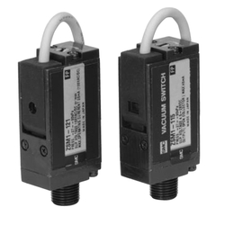
Specifications of Vacuum Pressure Switch / Diaphragm Type
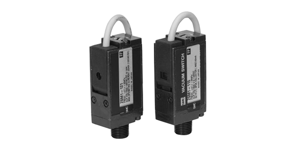
External appearance of vacuum pressure switch / diaphragm type
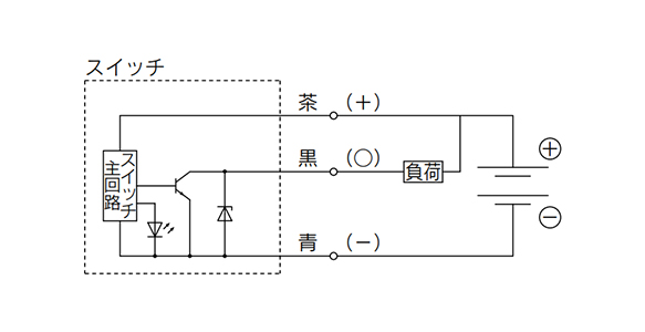
Connection method of ZSM1-115
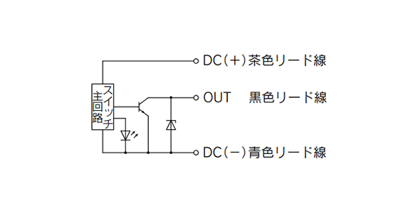
Internal circuit of ZSM1-115
- Brown lead wire: Connect to the power supply (+) terminal is necessary to operate the switch main circuit.
- Black lead wire: Connect to the load. (PLC input, relay)
- Blue lead wire: Connect to the power supply GND terminal.
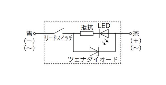
Internal circuit of ZSM1-121
Specifications
| Model | ZSM1-115 | ZSM1-121 |
|---|---|---|
| Switch specifications | Solid state | Contact (Reed Switch) |
| Fluid | Air and inert gas | |
| Maximum operating pressure | 0.5 MPa | |
| Set pressure range | -27 to -80 kPa | |
| Hysteresis | Max. 15 kPa | Max. 20 kPa |
| Repeat accuracy | ±10% or less | |
| Ambient and fluid temperature | -5~+60℃ (No freezing) | |
| Supply voltage | DC4.5 to 28 V | 100 V AC/DC or less |
| Indicator Light | ON lights | |
| Lead number | 3 | 2 |
| Port Size | R1/8 | |
| Weight | 65 g | |
Electrical Specifications
ZSM1-115
- Supply voltage: DC4.5 to 28 V
- Output (Open Collector): 28 V. Max 40 mA
- Current Consumption: 10 mA or less (DC24V)
ZSM1-121
- Supply voltage: AC/DC100V
- Maximum operating current range: 24 V or less: 50 mA, 48 V: 40 mA, 100 V: 20 mA
- Max. Contact Capacity: AC2VA, DC2W
Dimensions
(Units: mm)
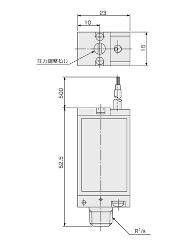
Dimensional drawing of vacuum pressure switch / diaphragm type
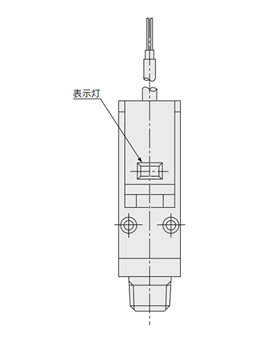
Dimensional drawing of ZSM1-115
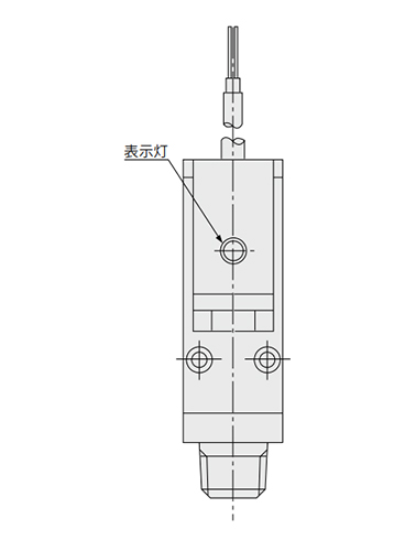
Dimensional drawing of ZSM1-121
Notes
Wiring
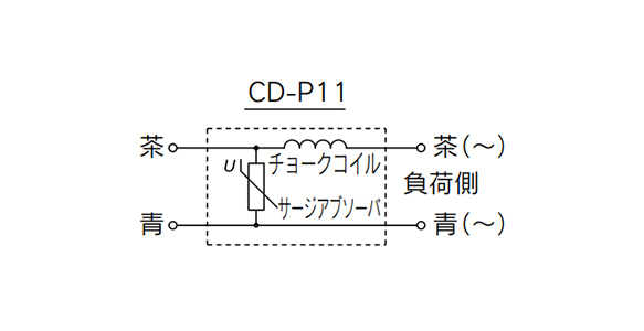
Contact protection box internal circuit
- * 1Do not apply pulling force to the power cord. It may cause damage.
- * 2Wiring precautions for ZSM1-121: When ZSM1-121 is connected in series, a voltage drop occurs due to the internal resistance of the light emitting diode. The voltage drop is approx. 2 V per switch. After checking the minimum drive voltage on the drive side, use within the range possible.
- * 3Since it does not have a built-in contact protection circuit, use the contact protection box (CD-P11) with an inductive load or a lead wire of 5 m or longer.
- * 4Contact protection box / connection method: To connect the switch body to the contact protection box, connect the lead wire on the side labeled SWITCH on the contact protection box and the lead wire from the switch body. Also, keep the lead wire length between the switch body and the contact protection box within 1 m, and set it as close as possible.
Mounting/Piping
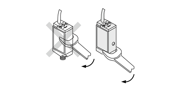
The main body must not be turned with a wrench
- * 1When handling the product, always hold it by the body and do not apply pulling force to the power cord.
- * 2When handling, do not drop or hit. It may cause damage.
- * 3When mounting on the pipe, apply a wrench to the fitting and screw in. Turning the main body with a wrench may cause damage.
- * 4The mounting direction can be horizontal or vertical.
Pressure source
- * 1When used as a suction confirmation switch, do not suck in water. It may cause malfunction or damage
- * 2Operating fluids are dedicated for air and inert gas. Corrosive fluid cannot be used.
- *See the SMC catalog for information other than that detailed above.
Part Number
|
|---|
| ZSM1-115 |
| ZSM1-115L |
| ZSM1-121 |
| ZSM1-121L |
| ZSM1-T115 |
| ZSM1-T115L |
| ZSM1-T121 |
| ZSM1-T121L |
| Part Number |
Standard Unit Price
| Minimum order quantity | Volume Discount | Pipe Port Type | Plumbing Thread Type | Nominal Pipe Thread Size | Operating Temperature Range (℃) | No. of Inputs | Power Supply Type | Power Supply Voltage (V) | Acquired Standards | Lead Wire | Hysteresis (MPa) | |
|---|---|---|---|---|---|---|---|---|---|---|---|---|---|---|
86.84 € | 1 | 26 Days | [Threads] Male thread | [Rc (R)] R | [1/8] 1/8 | - | - | DC | 4.5 to 28 | - | 0.5 m | - | ||
93.73 € | 1 | 26 Days | [Threads] Male thread | [Rc (R)] R | [1/8] 1/8 | - | - | DC | 4.5 to 28 | - | 3 | - | ||
68.56 € | 1 | 26 Days | [Threads] Male thread | [Rc (R)] R | [1/8] 1/8 | -5~60 | - | AC/DC | 100 | - | 0.5 m | - | ||
75.45 € | 1 | 4 Days | [Threads] Male thread | [Rc (R)] R | [1/8] 1/8 | - | - | AC/DC | 100 | - | 3 | - | ||
86.84 € | 1 | 26 Days | [Threads] Male thread | [NPT] NPTF | [1/8] 1/8 | -5~60 | 1 | DC | 4.5 to 28 | CE | 0.5 m | 0.015 | ||
93.73 € | 1 | 26 Days | [Threads] Male thread | [NPT] NPTF | [1/8] 1/8 | -5~60 | 1 | DC | 4.5 to 28 | CE | 3 m | 0.015 | ||
68.56 € | 1 | 26 Days | [Threads] Male thread | [NPT] NPTF | [1/8] 1/8 | -5~60 | 1 | AC/DC | 100 | CE | 0.5 m | 0.02 | ||
75.45 € | 1 | 26 Days | [Threads] Male thread | [NPT] NPTF | [1/8] 1/8 | -5~60 | 1 | AC/DC | 100 | CE | 3 m | 0.02 |
Loading...
Basic information
| Type | Pressure Switch | Fluid Type | Air / Nitrogen Gas / Carbonic Acid Gas / City Gas / Methane Gas / Propane gas | Sensor/Monitor Configuration | Separate Type, Connector Joint |
|---|---|---|---|---|---|
| Output Method | Switch | Fluid Characteristics | Inert | No. of Outputs | 1 |
| Pipe Connection Direction | Down |
Configure
Basic Attributes
-
Plumbing Thread Type
- Rc (R)
- NPT
- Rc (R)
-
Nominal Pipe Thread Size
- 1/8
- 1/8
-
No. of Inputs
- 1
-
Power Supply Type
- DC
- AC/DC
-
Power Supply Voltage(V)
- 100
- 4.5 to 28
-
Lead Wire
- 0.5 m
- 3
- 3 m
-
Hysteresis(MPa)
- 0.015
- 0.02
-
Type
- ZSM1
-
Pipe Port Type
- Threads
- Direct Mount
- Threads
-
Filter by CAD data type
- 2D
- 3D
Filter by standard shipping days
-
- All
- 4 Days or Less
- 26 Days or Less
Optional Attributes
- The specifications and dimensions of some parts may not be fully covered. For exact details, refer to manufacturer catalogs .
Tech Support
Payment Method


On-Demand Manufacturing
Certificates


Copyright © MISUMI Corporation All Rights Reserved.