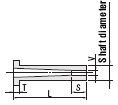
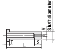
EJECTOR SLEEVES
Straight Ejector Sleeves

 |
 |
 |
 |
|||||||
| Material | Head Thick- ness (T) |
Concen- tricity between the hole and shaft diameters |
Hole diameter (V) Finishing |
Hole dia- meter (V) |
Smax. | Shaft dia- meter tole- rance |
Blank type |
L dimen- sion designa- tion type |
LCV dimension designation type | |
|---|---|---|---|---|---|---|---|---|---|---|
| Shaft dia- meter selec- tion |
Shaft diameter designa- tion |
|||||||||
 |
4mm (T4) |
 0.005 0.005 |
Grinding | +0.005 0 |
V×3 and S≤25 |
0 -0.005 |
- | - | ESV | ESVB |
| +0.01 0 |
V×
5 and S≤25 |
ESV-H | ESVB-H | |||||||
| 6·8mm (JIS) |
+0.005 0 |
V×3 and S≤25 |
ESVJ | ESVJB | ||||||
| 4mm (T4) |
 0.01 0.01 |
Wire cutting & Polishing |
+0.01 0 |
V×10 and S≤50 |
- | - | ESVK-H | ESVKB-H | ||
| 6·8mm (JIS) |
ESVKJ-H | ESVKJB-H | ||||||||
 |
4mm (T4) |
 0.03 0.03 |
Reaming | H7 | 50 | -0.01 -0.02 |
ESNV | ESNV-LC | ESNV-L | ESNVB |
| 6·8mm (JIS) |
- | - | ESNVJ | ESJVB | ||||||
| 4mm (T4) |
 0.06 0.06 |
100 (150) |
-0.01 -0.02 |
ESN | ESN-LC | ESN-L | ESNB | |||
| 6·8mm (JIS) |
-0.01 -0.02 (-0.01 -0.03) |
ESJ | ESJL | ESNJ | ESJB | |||||
Straight Ejector Sleeves -Tapered Type-

 |
 |
||||||
| Material | Head Thickness(T) | Concen- tricity between the hole and shaft diameters |
Hole diameter(V) Finishing |
Hole diameter(V) |
Smax. | Tip dia- meter (P) tole- rance |
L・V dimension designa- tion type |
|---|---|---|---|---|---|---|---|
| SKH51 equivalent | 4mm (T4) |
 0.003 0.003 |
Grinding | +0.005 0 |
V×3 | 0 -0.005 |
ESVX |
Short Ejector Sleeves (Straight Core Sleeves)

 Straight Core Sleeves are published on index of Shaped Inlay Core Pins for Boss.
 |
 |
||||||||
| Product name | Material | Head Thick- ness (T) |
Concen- tricity between the hole and shaft diameters |
Hole diameter (V) Finishing |
Hole diameter (V) |
Smax. (Reference) |
Tip diameter (P) tolerance |
L・V dimension designation type | |
|---|---|---|---|---|---|---|---|---|---|
| Shaft dia- meter selection |
Shaft diameter designa- tion |
||||||||
Short Ejector Sleeves |
SKD61 equivalent + Nitrided |
4mm (T4) |
 0.06 0.06 |
Reamers | H7 | 30 | -0.01 -0.02 |
ECB ECBB |
- |
| SKH51 equivalent |
 0.01 0.01 |
Wire cutting & Polishing |
+0.005 0 |
3 | 0 -0.005 |
EPBBH | |||
| +0.01 0 |
-0.01 -0.02 |
EPBB-H EPBB-M |
|||||||
| Straight Core Sleeves | SKH51 equivalent | 4mm (T4) |
 0.005 0.005 |
Grinding | +0.005 0 |
V×3 designation | 0 -0.005 |
CSV4T | CSVB4T |
| V×3 specification | CSHKV4T | CSHKBV4T | |||||||
| +0.01 0 |
V×3 designation | CSHL4T | CSHB4T | ||||||
| Wire cutting & Polishing |
V×10 specification | CSHK4T | CSHKB4T | ||||||
| 6 · 8mm (JIS) |
Grinding | +0.005 0 |
V×3 designation | CSV | CSVB | ||||
| V×3 specification | CSHKV | CSHKBV | |||||||
| +0.01 0 |
V×3 designation | CSHL | CSHB | ||||||
| Wire cutting & Polishing |
V×10 specification | CSHK | CSHKB | ||||||
| NAK80 | 4mm (T4) |
 0.005 0.005 |
Grinding | +0.005 0 |
V×3 designation | 0 -0.005 |
CSGLV4T | CSGBV4T | |
| V×3 specification | CSGKV4T | CSGKBV4T | |||||||
| +0.01 0 |
V×3 designation | CSGL4T | CSGB4T | ||||||
| Wire cutting & Polishing |
V×10 specification | CSGK4T | CSGKB4T | ||||||
| 6 · 8mm (JIS) |
Grinding | +0.005 0 |
V×3 designation | CSGLV | CSGBV | ||||
| V×3 specification | CSGKV | CSGKBV | |||||||
| +0.01 0 |
V×3 designation | CSGL | CSGB | ||||||
| Wire cutting & Polishing |
V×10 specification | CSGK | CSGKB | ||||||
Stepped Ejector Sleeves

 |
 |
 |
 |
|||||||
| Material | Head Thickness (T) |
Concen- tricity between the hole and shaft diameters |
Hole diameter (V) Finishing |
Hole diamete (V) |
Smax. | Tip dia- meter (P) tole- rance |
Blank type |
L dimen- sion designa- tion type |
L・V dimension designation type | |
|---|---|---|---|---|---|---|---|---|---|---|
| Shaft diameter selection | Shaft diameter designa- tion |
|||||||||
 |
4mm (T4) |
 0.005 0.005 |
Grinding | +0.005 0 |
V×3 | 0 -0.005 |
- | - | ESVF | ESVFB |
| V×3 and S≤25 |
- | - | ESVFE | ESVBF | ||||||
| +0.01 0 |
V×5 and S≤25 |
ESVFE-H | ESVBF-H | |||||||
| 6 · 8mm (JIS) |
+0.005 0 |
V×3 and S≤25 |
- | - | ESVJFE | ESVJBF | ||||
| 4mm (T4) |
 0.01 0.01 |
Wire cutting & Polishing |
+0.01 0 |
V×10 and S≤30 |
- | - | ESVKF-H | ESVKFB-H | ||
| V×10 and S≤50 |
- | - | ESVKFE-H | ESVKBF-H | ||||||
| 6 · 8mm (JIS) |
V×10 and S≤50 |
ESVKJFE-H | ESVKJBF-H | |||||||
 |
4mm (T4) |
 0.03 0.03 |
Reaming |
H7 | 50 | -0.01 -0.02 (-0.01 -0.03) |
- | - | ESNVF | - |
| 6 · 8mm (JIS) |
ESJVF | |||||||||
| 4mm (T4) |
 0.06 0.06 |
100 | ESNFT | ESNF-LC | ESNF | - | ||||
| 6 · 8mm (JIS) |
ESJFT | ESJF-LC | ESJF | |||||||
Stepped Ejector Sleeves -Relief Tapered Type-

 |
 |
||||||
| Material | Head Thickness(T) | Concen- tricity between the hole and shaft diameters |
Hole diameter (V) Finishing |
Hole diameter (V) |
Smax. | Tip diameter (P) tolerance |
L・V dimen- sion designa- tion type |
|---|---|---|---|---|---|---|---|
| SKH51 equivalent | 4mm (T4) |
 0.005 0.005 |
Grinding | +0.005 0 |
V×3 | 0 -0.005 |
ESVFX |
Ejector Sleeves & One-step Center Pin Sets

| Material | Head Thickness(T) | Sleeve shape | Center Pin shape | L dimension designation typ | L・V dimension designation type |
|---|---|---|---|---|---|
| SKH51 equivalent | 4mm (T4) |
Straight | Tip stepped straight | ESV-S-□ | - |
| SKD61 equivalent + Nitrided |
4mm (T4) |
Straight | Tip stepped straight | ESNS-□ | ESNP-□ |
| 6 · 8mm (JIS) |
ESJS-□ | ESJP-□ | |||
| 4mm (T4) |
Stepped | Tip stepped straight | ESNM-□ | ESND-□ | |
| 6 · 8mm (JIS) |
ESJM-□ | ESJD-□ |
Ejector Sleeve and Center Pin Combination Example
 |
 |
||||
| Center Pin Shaft Diameter(D or P)Tolerance | |||||
|---|---|---|---|---|---|
| 0 -0.005 |
-0.01 -0.02 |
||||
| Ejector sleeve hole diameter (V) tolerance |
+0.005 0 (precision class) |
 Suitable |
Because the clearance between the ejector sleeve and center pin is kept to 0.01 mm and below, this is used in cases where the plastic is conducive to the development of burrs, and for precision molds. |  Suitable |
Because the clearance between the ejector sleeve and the center pin is large, this is used in applications where smooth sliding is required.(*The hole diameter of the ejector sleeve can also be made 0.01 mm larger.) |
| +0.01 0 and H7 |
× Unsuitable |
Combination of the ejector sleeves and  shaft-diameter tolerance center pins is unsuitable, due to the large contact surface with the center pins. Where the same dimensions have been specified for hole diameter and shaft diameter, take caution as there have been problems with the pins not fitting the holes, the pins stopping partially into the holes and sliding not being smooth. shaft-diameter tolerance center pins is unsuitable, due to the large contact surface with the center pins. Where the same dimensions have been specified for hole diameter and shaft diameter, take caution as there have been problems with the pins not fitting the holes, the pins stopping partially into the holes and sliding not being smooth. |
 Suitable |
The minimum clearance required for fit between the ejector sleeve and center pin (0.01 mm) can be achieved. This is widely used in general applications, where the plastic is not conducive to the development of burrs. | |


