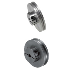
Round belt pulleys / V-groove, U-groove / grub screw clamping / steel, stainless steel, aluminium / black oxided, chemically nickel-plated, anodised (Part Numbers - CAD Download)
Part Number
Once your search is narrowed to one product,
the corresponding part number is displayed here.
- Drawing / Specifications
- 3D Preview 3D preview is available after complete configuration
- Part Numbers
- More Information
- Catalog
Back to the Category Round Belt Pulleys, Idlers
Technical Drawing - Round Belt Track Rollers

Open the technical drawing in the new window
Available dimensions and tolerances can be found under the tab More Information.
Basic Properties (e.g., material, hardness, coating, tolerance) - Round Belt Track Rollers
| Trapezoid Groove | U Groove | Material | Surface Treatment | ||
| Shape A | Shape B | Shape A | Shape B | ||
| MBRDF | MBRD | MBRF | MBR | EN 1.1191 Equiv. | Black Oxide |
| MBRDFM | MBRDM | MBRFM | MBRM | Electroless Nickel Plating | |
| - | MBRDS | - | MBRS | EN 1.4301 Equiv. | - |
| MBRDFA | MBRDA | MBRFA | MBRA | Aluminum Alloy 5000 series | Clear Anodize |
Further specifications can be found under the tab More Information.
Composition of a Product Code - Round Belt Track Rollers
| Part Number | - | Belt Radius | - | R | - | Shaft Bore Specification, I.D. |
| MBRDF30 MBR60 | - | 1.5 | - | 2 | - - | H5 N12 |
Alterations - Round Belt Track Rollers

General Information - Round Belt Track Rollers

Selection details of round belt discs/idler pulleys
- Material: aluminum, steel, stainless steel, resin type (polyacetal)
- Coatings: untreated, burnished, nickel-plated, anodized
- Groove shape: V-groove (trapezoid groove), U-groove
- Belt diameter: single groove, double groove
- Effective diameter: 2 to 10 mm
- Shaft diameter: 15 to 140 mm
- Mounting: 3 to 20 mm
Description/Basics
The round belt disk for mechanical engineering is generally intended for drive and power transmission.
A system with round belts and round belt disk can transmit force over larger distances. An idler pulley is recommended depending on the distance to the guide. This reduces oscillations in a belt drive and minimizes the risk of the belt jumping off the round belt pulley. In addition, the belt tension of a round belt is important for power transmission. Depending on the application, the tension can be produced via a round belt disk with integrated ball bearing (tension roller). In addition, the use of a tension roller can increase the wrap angle and thus the contact surface of the belt on the round belt disk. Round belt disks made of plastic are often used for tensioning the round belt.
In principle, MISUIM offers two types of round belt discs. These are available with a trapezoidal groove (V-groove) or radius (U-groove) suitable for the round belt. The V-groove round belt disks are adapted to the round belt and offer the advantage that they form up to three contact points for the round belt due to their shape. In comparison, round belt disks with a V-groove can thus have a higher slip torque.
MISUMI also offers round belt disks with two grooves for drives mounted side-by-side. The combination of two round belt disks can be absorbed with force and simultaneously released and forwarded. In pulleys for round belts with double grooves, the force can also be delivered in different directions or systems. Therefore, it may be possible to forgo a drive unit and reduce costs.
The drive wheels for round belts can be fastened on a axles / rotary shafts in various ways. A flat round belt disk is mounted on an axle using a clamping screw. MISUMI also offers this as a round belt disk with hub and optionally with keyways. Another commonly used variant is the belt pulley with clamping scar.
The belt pulleys for round belts can often be found in transport technology to convey light objects. These are usually operated in a permanent and constant transport.
If higher forces occur in a system and any slip is undesirable, a timing pulleys can be used.
Application Examples - Round Belt Track Rollers

Application example conveyor belt
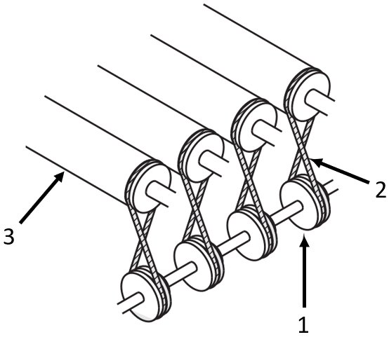
(1) Round belt disk with double groove, (2) rotary shaft, (3) Round belt, (4) Workpiece
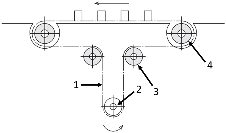
Application example conveyor belt
(1) Round belt, (2) Motor, (3) Idler pulley/return roller, (4) Drive wheel for round belt
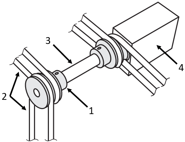
Application example
(1) Round belt disc with hub, (2) round belt, (3) rotary shaft, (4) bearing housing
Industrial Applications


Part Number:
- In order to open the 3D preview, the part number must be fixed.
3D preview is not available, because the part number has not yet been determined.
| Part Number |
Standard Unit Price
| Minimum order quantity | Volume Discount | RoHS | Groove Shape | Applicable Belt Dia. (Ø) | Pitch Circle Dia. P.D. (Ø) | Pulley Type | Nominal Width W (mm) | Material | Surface Treatment | R (mm) | Belt Radius (mm) | NK | Shaft Bore Specifications (New JIS Keyway Hole + Tap) [N] (mm) | Shaft Bore Specifications (Old JIS Keyway Hole + Tap) [C] (mm) | Shaft Bore Specifications (Round Hole + Tap) [P] (mm) | Shaft Bore Specifications (Round Hole) [H] (mm) | |
|---|---|---|---|---|---|---|---|---|---|---|---|---|---|---|---|---|---|---|---|
- | 1 | 10 Days | 10 | Trapezoid Groove | 6 | 60 | Shape B | 6.6 | EN 1.4301 Equiv. | Not Provided | - | 3 | - | - | 10 | - | - | ||
- | 1 | 10 Days | 10 | Trapezoid Groove | 6 | 60 | Shape B | 6.6 | EN 1.4301 Equiv. | Not Provided | - | 3 | - | - | - | - | 6.35 | ||
- | 1 | 10 Days | 10 | Trapezoid Groove | 6 | 60 | Shape B | 6.6 | EN 1.4301 Equiv. | Not Provided | - | 3 | - | - | - | - | 5 ~ 20 | ||
- | 1 | 10 Days | 10 | Trapezoid Groove | 6 | 60 | Shape B | 6.6 | EN 1.4301 Equiv. | Not Provided | - | 3 | - | 8 | - | - | - | ||
- | 1 | 10 Days | 10 | Trapezoid Groove | 6 | 60 | Shape B | 6.6 | EN 1.4301 Equiv. | Not Provided | - | 3 | - | 8 ~ 15 | - | - | - | ||
- | 1 | 10 Days | 10 | Trapezoid Groove | 6 | 60 | Shape B | 6.6 | EN 1.4301 Equiv. | Not Provided | - | 3 | 10 | - | - | - | - | ||
- | 1 | 10 Days | 10 | Trapezoid Groove | 6 | 60 | Shape B | 6.6 | EN 1.4301 Equiv. | Not Provided | - | 3 | - | - | - | 6.35 | - | ||
- | 1 | 10 Days | 10 | Trapezoid Groove | 6 | 60 | Shape B | 6.6 | EN 1.4301 Equiv. | Not Provided | - | 3 | - | - | - | 5 ~ 20 | - | ||
- | 1 | 10 Days | 10 | Trapezoid Groove | 5 | 75 | Shape B | 5.5 | EN 1.4301 Equiv. | Not Provided | - | 2.5 | - | - | 10 | - | - | ||
- | 1 | 10 Days | 10 | Trapezoid Groove | 5 | 75 | Shape B | 5.5 | EN 1.4301 Equiv. | Not Provided | - | 2.5 | - | - | - | - | 6.35 | ||
- | 1 | 10 Days | 10 | Trapezoid Groove | 5 | 75 | Shape B | 5.5 | EN 1.4301 Equiv. | Not Provided | - | 2.5 | - | - | - | - | 5 ~ 20 | ||
- | 1 | 10 Days | 10 | Trapezoid Groove | 5 | 75 | Shape B | 5.5 | EN 1.4301 Equiv. | Not Provided | - | 2.5 | - | 8 | - | - | - | ||
- | 1 | 10 Days | 10 | Trapezoid Groove | 5 | 75 | Shape B | 5.5 | EN 1.4301 Equiv. | Not Provided | - | 2.5 | - | 8 ~ 15 | - | - | - | ||
- | 1 | 10 Days | 10 | Trapezoid Groove | 5 | 75 | Shape B | 5.5 | EN 1.4301 Equiv. | Not Provided | - | 2.5 | 10 | - | - | - | - | ||
- | 1 | 10 Days | 10 | Trapezoid Groove | 5 | 75 | Shape B | 5.5 | EN 1.4301 Equiv. | Not Provided | - | 2.5 | - | - | - | 6.35 | - | ||
- | 1 | 10 Days | 10 | Trapezoid Groove | 5 | 75 | Shape B | 5.5 | EN 1.4301 Equiv. | Not Provided | - | 2.5 | - | - | - | 5 ~ 20 | - | ||
- | 1 | 10 Days | 10 | Trapezoid Groove | 6 | 75 | Shape B | 6.6 | EN 1.4301 Equiv. | Not Provided | - | 3 | - | - | 10 | - | - | ||
- | 1 | 10 Days | 10 | Trapezoid Groove | 6 | 75 | Shape B | 6.6 | EN 1.4301 Equiv. | Not Provided | - | 3 | - | - | - | - | 6.35 | ||
- | 1 | 10 Days | 10 | Trapezoid Groove | 6 | 75 | Shape B | 6.6 | EN 1.4301 Equiv. | Not Provided | - | 3 | - | - | - | - | 5 ~ 20 | ||
- | 1 | 10 Days | 10 | Trapezoid Groove | 6 | 75 | Shape B | 6.6 | EN 1.4301 Equiv. | Not Provided | - | 3 | - | 8 | - | - | - | ||
- | 1 | 10 Days | 10 | Trapezoid Groove | 6 | 75 | Shape B | 6.6 | EN 1.4301 Equiv. | Not Provided | - | 3 | - | 8 ~ 15 | - | - | - | ||
- | 1 | 10 Days | 10 | Trapezoid Groove | 6 | 75 | Shape B | 6.6 | EN 1.4301 Equiv. | Not Provided | - | 3 | 10 | - | - | - | - | ||
- | 1 | 10 Days | 10 | Trapezoid Groove | 6 | 75 | Shape B | 6.6 | EN 1.4301 Equiv. | Not Provided | - | 3 | - | - | - | 6.35 | - | ||
- | 1 | 10 Days | 10 | Trapezoid Groove | 6 | 75 | Shape B | 6.6 | EN 1.4301 Equiv. | Not Provided | - | 3 | - | - | - | 5 ~ 20 | - | ||
- | 1 | 10 Days | 10 | Trapezoid Groove | 4 | 80 | Shape B | 4.4 | EN 1.4301 Equiv. | Not Provided | - | 2 | - | - | 10 | - | - | ||
- | 1 | 10 Days | 10 | Trapezoid Groove | 4 | 80 | Shape B | 4.4 | EN 1.4301 Equiv. | Not Provided | - | 2 | - | - | - | - | 6.35 | ||
- | 1 | 10 Days | 10 | Trapezoid Groove | 4 | 80 | Shape B | 4.4 | EN 1.4301 Equiv. | Not Provided | - | 2 | - | - | - | - | 5 ~ 20 | ||
- | 1 | 10 Days | 10 | Trapezoid Groove | 4 | 80 | Shape B | 4.4 | EN 1.4301 Equiv. | Not Provided | - | 2 | - | 8 | - | - | - | ||
- | 1 | 10 Days | 10 | Trapezoid Groove | 4 | 80 | Shape B | 4.4 | EN 1.4301 Equiv. | Not Provided | - | 2 | - | 8 ~ 15 | - | - | - | ||
- | 1 | 10 Days | 10 | Trapezoid Groove | 4 | 80 | Shape B | 4.4 | EN 1.4301 Equiv. | Not Provided | - | 2 | 10 | - | - | - | - | ||
- | 1 | 10 Days | 10 | Trapezoid Groove | 4 | 80 | Shape B | 4.4 | EN 1.4301 Equiv. | Not Provided | - | 2 | - | - | - | 6.35 | - | ||
- | 1 | 10 Days | 10 | Trapezoid Groove | 4 | 80 | Shape B | 4.4 | EN 1.4301 Equiv. | Not Provided | - | 2 | - | - | - | 5 ~ 20 | - | ||
- | 1 | 10 Days | 10 | Trapezoid Groove | 5 | 80 | Shape B | 5.5 | EN 1.4301 Equiv. | Not Provided | - | 2.5 | - | - | 10 | - | - | ||
- | 1 | 10 Days | 10 | Trapezoid Groove | 5 | 80 | Shape B | 5.5 | EN 1.4301 Equiv. | Not Provided | - | 2.5 | - | - | - | - | 6.35 | ||
- | 1 | 10 Days | 10 | Trapezoid Groove | 5 | 80 | Shape B | 5.5 | EN 1.4301 Equiv. | Not Provided | - | 2.5 | - | - | - | - | 5 ~ 20 | ||
- | 1 | 10 Days | 10 | Trapezoid Groove | 5 | 80 | Shape B | 5.5 | EN 1.4301 Equiv. | Not Provided | - | 2.5 | - | 8 | - | - | - | ||
- | 1 | 10 Days | 10 | Trapezoid Groove | 5 | 80 | Shape B | 5.5 | EN 1.4301 Equiv. | Not Provided | - | 2.5 | - | 8 ~ 15 | - | - | - | ||
- | 1 | 10 Days | 10 | Trapezoid Groove | 5 | 80 | Shape B | 5.5 | EN 1.4301 Equiv. | Not Provided | - | 2.5 | 10 | - | - | - | - | ||
- | 1 | 10 Days | 10 | Trapezoid Groove | 5 | 80 | Shape B | 5.5 | EN 1.4301 Equiv. | Not Provided | - | 2.5 | - | - | - | 6.35 | - | ||
- | 1 | 10 Days | 10 | Trapezoid Groove | 5 | 80 | Shape B | 5.5 | EN 1.4301 Equiv. | Not Provided | - | 2.5 | - | - | - | 5 ~ 20 | - | ||
- | 1 | 10 Days | 10 | Trapezoid Groove | 6 | 80 | Shape B | 6.6 | EN 1.4301 Equiv. | Not Provided | - | 3 | - | - | 10 | - | - | ||
- | 1 | 10 Days | 10 | Trapezoid Groove | 6 | 80 | Shape B | 6.6 | EN 1.4301 Equiv. | Not Provided | - | 3 | - | - | - | - | 6.35 | ||
- | 1 | 10 Days | 10 | Trapezoid Groove | 6 | 80 | Shape B | 6.6 | EN 1.4301 Equiv. | Not Provided | - | 3 | - | - | - | - | 5 ~ 20 | ||
- | 1 | 10 Days | 10 | Trapezoid Groove | 6 | 80 | Shape B | 6.6 | EN 1.4301 Equiv. | Not Provided | - | 3 | - | 8 | - | - | - | ||
- | 1 | 10 Days | 10 | Trapezoid Groove | 6 | 80 | Shape B | 6.6 | EN 1.4301 Equiv. | Not Provided | - | 3 | - | 8 ~ 15 | - | - | - | ||
- | 1 | 10 Days | 10 | Trapezoid Groove | 6 | 80 | Shape B | 6.6 | EN 1.4301 Equiv. | Not Provided | - | 3 | 10 | - | - | - | - | ||
- | 1 | 10 Days | 10 | Trapezoid Groove | 6 | 80 | Shape B | 6.6 | EN 1.4301 Equiv. | Not Provided | - | 3 | - | - | - | 6.35 | - | ||
- | 1 | 10 Days | 10 | Trapezoid Groove | 6 | 80 | Shape B | 6.6 | EN 1.4301 Equiv. | Not Provided | - | 3 | - | - | - | 5 ~ 20 | - | ||
- | 1 | 10 Days | 10 | Trapezoid Groove | 6 | 95 | Shape B | 6.6 | EN 1.4301 Equiv. | Not Provided | - | 3 | - | - | 10 | - | - | ||
- | 1 | 10 Days | 10 | Trapezoid Groove | 6 | 95 | Shape B | 6.6 | EN 1.4301 Equiv. | Not Provided | - | 3 | - | - | - | - | 6.35 | ||
- | 1 | 10 Days | 10 | Trapezoid Groove | 6 | 95 | Shape B | 6.6 | EN 1.4301 Equiv. | Not Provided | - | 3 | - | - | - | - | 5 ~ 20 | ||
- | 1 | 10 Days | 10 | Trapezoid Groove | 6 | 95 | Shape B | 6.6 | EN 1.4301 Equiv. | Not Provided | - | 3 | - | 8 | - | - | - | ||
- | 1 | 10 Days | 10 | Trapezoid Groove | 6 | 95 | Shape B | 6.6 | EN 1.4301 Equiv. | Not Provided | - | 3 | - | 8 ~ 15 | - | - | - | ||
- | 1 | 10 Days | 10 | Trapezoid Groove | 6 | 95 | Shape B | 6.6 | EN 1.4301 Equiv. | Not Provided | - | 3 | 10 | - | - | - | - | ||
- | 1 | 10 Days | 10 | Trapezoid Groove | 6 | 95 | Shape B | 6.6 | EN 1.4301 Equiv. | Not Provided | - | 3 | - | - | - | 6.35 | - | ||
- | 1 | 10 Days | 10 | Trapezoid Groove | 6 | 95 | Shape B | 6.6 | EN 1.4301 Equiv. | Not Provided | - | 3 | - | - | - | 5 ~ 20 | - | ||
- | 1 | 10 Days | 10 | Trapezoid Groove | 6 | 100 | Shape B | 6.6 | EN 1.4301 Equiv. | Not Provided | - | 3 | - | - | 10 | - | - | ||
- | 1 | 10 Days | 10 | Trapezoid Groove | 6 | 100 | Shape B | 6.6 | EN 1.4301 Equiv. | Not Provided | - | 3 | - | - | - | - | 6.35 | ||
- | 1 | 10 Days | 10 | Trapezoid Groove | 6 | 100 | Shape B | 6.6 | EN 1.4301 Equiv. | Not Provided | - | 3 | - | - | - | - | 5 ~ 20 | ||
- | 1 | 10 Days | 10 | Trapezoid Groove | 6 | 100 | Shape B | 6.6 | EN 1.4301 Equiv. | Not Provided | - | 3 | - | 8 | - | - | - |
Loading...
Back to the Category Round Belt Pulleys, Idlers
Technical Drawing - Round Belt Track Rollers

Open the technical drawing in the new window
Specification Tables - Round Belt Track Rollers
| Part Number | Belt Radius | R | Shaft Bore Specification, I.D. Selection | D1 | D2 | h | W | T | L | ℓ | D | m | Applicable Belt Dia. | Unit Price | |||||||||
| 1mm Increment | Selection | MBRDF MBRF | MBRDFM MBRFM | MBRDFA MBRFA | MBRD MBR | MBRDM MBRM | MBRDS MBRS | MBRDA MBRA | |||||||||||||||
| Type | P.D. | Trapezoid | U Groove | H, P(H7) | N (New JIS) | C (Old JIS) | |||||||||||||||||
| Trapezoid Groove A Shape MBRDF MBRDFM MBRDFA B Shape MBRD MBRDM MBRDS MBRDA U Groove A Shape MBRF MBRFM MBRFA B Shape MBR MBRM MBRS MBRA | *15 | 1 | 4~7 | - | - | 17 | 13 | 1 | 2.2 | 5 | 11 | 3 | 12 | M3 | 2 | - | - | - | |||||
| *20 | 4~12 | 22 | 18 | 16 | |||||||||||||||||||
| *30 | 8, 10, NK10 | 32 | 28 | 20 | |||||||||||||||||||
| *40 | 42 | 38 | |||||||||||||||||||||
| 20 | 1.5 | 4~12 | 8 | 22 | 17 | 1.5 | 3.3 | 10 | 16 | 3 | 16 | M3 | 3 | ||||||||||
| 30 | 5~12 | 8, 10, NK10 | 32 | 27 | 20 | ||||||||||||||||||
| 40 | 42 | 37 | |||||||||||||||||||||
| 45 | 5~20 | 8~20 (8~15) | 10 | 47 | 42 | 20 | 5 | 25 | M4 | ||||||||||||||
| 60 | 62 | 57 | |||||||||||||||||||||
| 18 | 2 | 5~12 | (8) | - | 20 | 14 | 2 | 4.4 | 10 | 16 | 3 | 16 | M3 | 4 | |||||||||
| 23 | 8, 10, NK10 | 25 | 19 | 20 | |||||||||||||||||||
| 28 | 30 | 24 | |||||||||||||||||||||
| 30 | 32 | 26 | |||||||||||||||||||||
| 40 | 42 | 36 | |||||||||||||||||||||
| 45 | 5~20 | 8~20 (8~15) NK10 | 10 | 47 | 41 | 20 | 5 | 25 | M4 | ||||||||||||||
| 48 | 50 | 44 | |||||||||||||||||||||
| 60 | 62 | 56 | |||||||||||||||||||||
| 80 | 82 | 76 | |||||||||||||||||||||
| 28 | 2.5 | 5~12 | 8, 10, NK10 | - | 30 | 23 | 2.5 | 5.5 | 10 | 16 | 3 | 20 | M3 | 5 | |||||||||
| 40 | 5~20 | 8~20 (8~15) NK10 | 10 | 42 | 35 | 20 | 5 | 25 | M4 | ||||||||||||||
| 48 | 50 | 43 | |||||||||||||||||||||
| 50 | 52 | 45 | |||||||||||||||||||||
| 60 | 62 | 55 | |||||||||||||||||||||
| 75 | 77 | 70 | |||||||||||||||||||||
| 80 | 82 | 75 | |||||||||||||||||||||
| 28 | 3 | 5~12 | 8, 10, NK10 | - | 30 | 22 | 3 | 6.6 | 10 | 16 | 3 | 20 | M3 | 6 | |||||||||
| 38 | 40 | 32 | 20 | 5 | M4 | ||||||||||||||||||
| 48 | 5~20 | 8~20 (8~15) NK10 | 10 | 50 | 42 | 25 | |||||||||||||||||
| 50 | 52 | 44 | |||||||||||||||||||||
| 58 | 60 | 52 | |||||||||||||||||||||
| 60 | 62 | 54 | |||||||||||||||||||||
| 75 | 77 | 69 | |||||||||||||||||||||
| 80 | 82 | 74 | |||||||||||||||||||||
| 95 | 97 | 89 | |||||||||||||||||||||
| 100 | 102 | 94 | |||||||||||||||||||||
| 50 | 4 | 5~20 | 8~20 NK10 | 10 12 15 | 52 | 42 | 4 | 8.8 | 12 | 24 | 6 | 30 | M4 (M5) *1 | 8 | - | ||||||||
| 60 | 62 | 52 | - | ||||||||||||||||||||
| 80 | 82 | 72 | - | ||||||||||||||||||||
| 100 | 102 | 92 | - | ||||||||||||||||||||
| 120 | 122 | 112 | - | ||||||||||||||||||||
| 60 | 5 | 5~20 | 8~20 NK10 | 10 12 15 | 62 | 50 | 5 | 11 | 15 | 27 | 6 | 30 | M4 (M5) *1 | 10 | - | ||||||||
| 80 | 82 | 70 | - | ||||||||||||||||||||
| 100 | 102 | 90 | - | ||||||||||||||||||||
| 120 | 122 | 110 | - | ||||||||||||||||||||
| 140 | 142 | 130 | - | ||||||||||||||||||||
Shaft Hole Dia. 9 is not available for Shaft Hole Specification N.
Sizes with * will be B Shaps only. *1 When shaft diameter is 15mm or more, set screw size is (M5).
For keyway dimensions, see P.1377.
Specify NK10 when Keyway + Tap with shaft bore dia. 10 and keyway width 4.0mm (height 1.8mm) is desired.
Alterations - Round Belt Track Rollers

Basic information
| Pulleys/Idlers | Pulleys | Number of Grooves | 1-fach | Product Type | Pulley (No Bearing) |
|---|
Configure
Basic Attributes
-
Groove Shape
-
 Trapezoid Groove
 -
 U Groove
-
-
Applicable Belt Dia.(Ø)
-
Pitch Circle Dia. P.D.(Ø)
-
Pulley Type
-
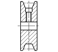 Shape A
 -
 Shape B
-
-
Nominal Width W(mm)
-
Material
- EN 1.1191 Equiv.
- EN 1.4301 Equiv.
-
R(mm)
-
Belt Radius(mm)
- 1
- 1.5
- 2
- 2.5
- 3
- 4
- 5
-
NK
-
Shaft Bore Specifications (New JIS Keyway Hole + Tap) [N](mm)
-
Shaft Bore Specifications (Old JIS Keyway Hole + Tap) [C](mm)
-
Shaft Bore Specifications (Round Hole + Tap) [P](mm)
-
Shaft Bore Specifications (Round Hole) [H](mm)
-
Type
- MBR
- MBRA
- MBRD
- MBRDA
- MBRDF
- MBRDFA
- MBRDFM
- MBRDM
- MBRDS
- MBRF
- MBRFA
- MBRFM
- MBRM
- MBRS
-
Surface Treatment
- Not Provided
- Black Oxide
- Electroless Nickel Plating
- Clear Anodized Aluminum
-
Filter by CAD data type
- 2D
- 3D
Filter by standard shipping days
-
- All
- 10 Days or Less
Optional Attributes
- The specifications and dimensions of some parts may not be fully covered. For exact details, refer to manufacturer catalogs .
Frequently Asked Questions (FAQ)
-
Question:
What is the dimension of the keyway?
-
Answer:
The keyway of MISUMI round belt track rollers are manufactured according to the new JIS standard (B1301) or the previous JIS standard. Therefore, it is recommended to use a keyway from MISUMI, as these are matched. Dimensions are shown in the Keyway Overview PDF
-
Question:
How can round belts prevent the round belts from popping off?
-
Answer:
A round belt can jump or slip off the round belts by adjusting the correct belt tension. Depending on the application and the distance between the round belt track rollers, it requires an idler pulley. MISUMI also offers this for the appropriate belt diameters. These are already equipped with ball bearings and available in steel, stainless steel, aluminum and plastic.
-
Question:
Are round belt track rollers suitable for strong forces?
-
Answer:
If higher forces are transmitted, a round belt track roller with trapezoidal groove (V-groove) can be utilised. However, if very high forces are transmitted and slip is undesirable, a synchronous pulley and synchronous belt can be used. These can transmit higher forces without slipping.
-
Question:
How can an idler pulley be mounted?
-
Answer:
The idler pulley for the round belt comes already equipped with a ball bearing. Here, the bearing can be mounted on a clamping device with a cantilever pin. However, MISUMI also offers idler pulleys round belts with already pressed axle bolts. This can simplify assembly and reduce the assembly time.
-
Question:
Are there round belt track rollers made of aluminum?
-
Answer:
In addition, MISUMI offers in its product assortment round belt track rollers made of aluminum. These have good corrosion resistance and a low density. The round belt track rollers made of aluminum are well-suited for saving weight and generate a lower inertial mass during operation compared to other materials. In addition, the aluminum round belt track rollers are available with single or double groove, as well as V-groove (trapezoidal groove) and U-groove.
Complementary Products
Tech Support
- Technical Support
- Tel:+49 69 668173-0 / FAX:+49 69 668173-360
- Technical Inquiry

