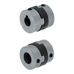
Oldham couplings / grub screw locking, feather key / 1 disc: CFK / body: aluminium
Click on this image to zoom in.
Click on this image to zoom in.

Part Number
Once your search is narrowed to one product,
the corresponding part number is displayed here.
*One set screw location for D6 and D8.
Operating Temperature: -40°C ~ 90°C
The lateral, angular, and axial misalignment values shown are for each occurring individually. When multiple misalignments are occurring simultaneously, the allowable maximum value of each will be reduced to 1/2.
For the selection criteria and alignment procedures, see >>P.1061
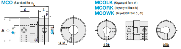
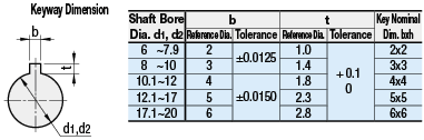
| Standard Bore | Keywayed Bore | Material | Accessory | |||
| d1 (One Side) | d2 (One Side) | d1, d2 (Both Sides) | Hub | Spacer | ||
| MCO | MCOLK | MCORK | MCOWK | EN 1.4301 Equiv. Sintered Alloy | Carbon Reinforced Resin | Set Screw |
Specifications
| Part Number | - | Shaft Bore Dia. d1 | - | Shaft Bore Dia. d2 |
| MCO20 | - | 6 | - | 6 |
| MCOLK20 | - | 8 | - | 12 |
| MCOWK20 | - | 10 | - | 12 |
| Part Number | d1, d2 Selection (d1≤d2) Keywayed Bore Type is selectable for diameter 6 or larger | D | D1 | d3 | L | ℓ | F | Set Screw | Unit Price | ||||||||||||||||||||||
| Type | No. | M | Tightening Torque (N • m) | MCO | MCOLK MCORK | MCOWK | |||||||||||||||||||||||||
| MCO MCOLK MCORK MCOWK | 6 | 1 | 1.5 | 2 | 6 | 6.2 | 2.4 | 8.4 | 3 | 1.5 | M1.6 | 0.15 | - | - | |||||||||||||||||
| 8 | 1 | 2 | 3 | 8 | 8.2 | 3.4 | 9.6 | 3.5 | 1.7 | - | - | ||||||||||||||||||||
| 10 | 2 | 3 | 4 | 10 | 10.2 | 4.4 | 10.2 | 3.7 | 1.8 | M2 | 0.3 | - | - | ||||||||||||||||||
| 12 | 3 | 4 | 5 | 12 | 12.5 | 4.0 | 14.2 | 5.2 | 2.5 | M3 | 0.7 | - | - | ||||||||||||||||||
| 15 | 4 | 5 | 6 | 6.35 | 7 | 8 | 14.5 | 15 | 5.0 | 16 | 5.4 | 2.6 | |||||||||||||||||||
| 17 | 5 | 6 | 6.35 | 7 | 8 | 16.8 | 17.5 | 7.2 | 19.8 | 6.7 | 3.2 | M4 | 1.7 | ||||||||||||||||||
| 20 | 6 | 6.35 | 7 | 8 | 9.53 | 10 | 11 | 12 | 20 | 21 | 8.2 | 21.4 | 7 | 3.4 | |||||||||||||||||
| 26 | 6 | 6.35 | 7 | 8 | 9.53 | 10 | 11 | 12 | 14 | 26 | 27 | 12.0 | 25.6 | 9 | 4 | ||||||||||||||||
| 30 | 8 | 10 | 12 | 14 | 30 | 31 | 13.0 | 33 | 12 | 6 | |||||||||||||||||||||
| 34 | 10 | 11 | 12 | 14 | 15 | 16 | 34 | 35 | 13.0 | 34 | 13 | 5.5 | M5 | 4.0 | |||||||||||||||||
| 38 | 10 | 12 | 14 | 15 | 16 | 18 | 20 | 38 | 41 | 16.0 | 40 | 15 | 7 | ||||||||||||||||||
| Part Number | Allowable Torque (N • m) | Angular Misalignment (°) | Lateral Misalignment (mm) | Static Torsional Spring Constant (N • m/rad) | Max. Rotational Speed (r/min) | Moment of Inertia (kg • m2) | Allowable Axial Misalignment (mm) | Mass (g) | |
| Type | No. | ||||||||
| MCO MCOLK MCORK MCOWK | 6 | 0.3 | 3 | 0.3 | 9 | 12000 | 1.5x10⁻⁸ | ±0.25 | 1.5 |
| 8 | 0.5 | 0.4 | 13 | 2.2x10⁻⁸ | ±0.3 | 2.5 | |||
| 10 | 0.8 | 0.4 | 21 | 3.6x10⁻⁸ | ±0.32 | 4 | |||
| 12 | 1 | 0.5 | 44 | 1.6x10⁻⁷ | ±0.35 | 8 | |||
| 15 | 1.6 | 0.8 | 90 | 10000 | 3.5x10⁻⁷ | ±0.45 | 11 | ||
| 17 | 2.2 | 1 | 250 | 7.8x10⁻⁷ | ±0.55 | 18 | |||
| 20 | 3.2 | 1.5 | 340 | 8000 | 1.7x10⁻⁶ | ±0.6 | 29 | ||
| 26 | 6 | 2 | 420 | 6500 | 6.2x10⁻⁶ | 65 | |||
| 30 | 15 | 2 | 1200 | 6200 | 2x10⁻⁵ | 100 | |||
| 34 | 16 | 2.5 | 2400 | 6000 | 2.5x10⁻⁵ | 155 | |||
| 38 | 28 | 2.5 | 3500 | 5800 | 8x10⁻⁵ | 240 | |||
Alterations
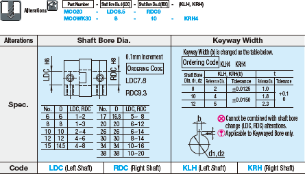
Part Number:
- In order to open the 3D preview, the part number must be fixed.
3D preview is not available, because the part number has not yet been determined.
Part Number
|
|---|
| MCO15-[4,5,6,6.35,7,8]-[4,5,6,6.35,7,8] |
| MCO15-[4,5,6,6.35,7,8]-RDC[4-8/0.1] |
| MCO15-LDC[4-8/0.1]-[4,5,6,6.35,7,8] |
| MCO15-LDC[4-8/0.1]-RDC[4-8/0.1] |
| MCO17-[5,6,6.35,7,8]-[5,6,6.35,7,8] |
| MCO17-[5,6,6.35,7,8]-RDC[5-8/0.1] |
| MCO17-LDC[5-8/0.1]-[5,6,6.35,7,8] |
| MCO17-LDC[5-8/0.1]-RDC[5-8/0.1] |
| MCOLK15-[6,6.35,7,8]-[6,6.35,7,8] |
| MCOLK15-[6,6.35,7,8]-RDC[6-8/0.1] |
| MCOLK15-LDC[6-8/0.1]-[6,6.35,7,8] |
| MCOLK15-LDC[6-8/0.1]-RDC[6-8/0.1] |
| MCOLK17-[6,6.35,7,8]-[6,6.35,7,8] |
| MCOLK17-[6,6.35,7,8]-RDC[6-8/0.1] |
| MCOLK17-LDC[6-8/0.1]-[6,6.35,7,8] |
| MCOLK17-LDC[6-8/0.1]-RDC[6-8/0.1] |
| MCORK15-[4,5,6,6.35,7,8]-[6,6.35,7,8] |
| MCORK15-[4,5,6,6.35,7,8]-RDC[6-8/0.1] |
| MCORK15-LDC[4-8/0.1]-[6,6.35,7,8] |
| MCORK15-LDC[4-8/0.1]-RDC[6-8/0.1] |
| MCORK17-[5,6,6.35,7,8]-[6,6.35,7,8] |
| MCORK17-[5,6,6.35,7,8]-RDC[6-8/0.1] |
| MCORK17-LDC[5-8/0.1]-[6,6.35,7,8] |
| MCORK17-LDC[5-8/0.1]-RDC[6-8/0.1] |
| MCOWK15-[6,6.35,7,8]-[6,6.35,7,8] |
| MCOWK15-[6,6.35,7,8]-RDC[6-8/0.1] |
| MCOWK15-LDC[6-8/0.1]-[6,6.35,7,8] |
| MCOWK15-LDC[6-8/0.1]-RDC[6-8/0.1] |
| MCOWK17-[6,6.35,7,8]-[6,6.35,7,8] |
| MCOWK17-[6,6.35,7,8]-RDC[6-8/0.1] |
| MCOWK17-LDC[6-8/0.1]-[6,6.35,7,8] |
| MCOWK17-LDC[6-8/0.1]-RDC[6-8/0.1] |
| Part Number |
Standard Unit Price
| Minimum order quantity | Volume Discount | RoHS | Allowable Torque Range (N•m) | Shaft Bore Dia. 1 d1 (or d) (mm) | Shaft Bore Dia. 2 d2 (or d) (mm) | O.D. D (mm) | Overall Length (mm) | Max. Rotational Speed Range (r/min) | Allowable Torque (Nm) | Max. Rotational Speed (r/min) | Allowable Lateral Misalignment Range (mm) | Allowable Lateral Misalignment (mm) | Allowable Axial Misalignment (mm) | Moment of Inertia (kg・m2) | Shaft Bore Shape | Shaft I.D. d1 Change Hole Dia. [LDC] Specified in 0.1mm Increment | Shaft I.D. d2 Change Hole Dia. [RDC] Specified in 0.1mm Increment | |
|---|---|---|---|---|---|---|---|---|---|---|---|---|---|---|---|---|---|---|---|---|
- | 1 | 7 Days | 10 | 1.01 to 3.00 | 4 ~ 8 | 4 ~ 8 | 14.5 | 16 | 4,001 to 10,000 | 1.6 | 10000 | 0.41 to 1.0 | 0.8 | +0.45/-0.45 | 3.5x10⁻⁷ | Standard Holes | - | - | ||
- | 1 | 7 Days | 10 | 1.01 to 3.00 | 4 ~ 8 | - | 14.5 | 16 | 4,001 to 10,000 | 1.6 | 10000 | 0.41 to 1.0 | 0.8 | +0.45/-0.45 | 3.5x10⁻⁷ | Standard Holes | - | 4 ~ 8 | ||
- | 1 | 7 Days | 10 | 1.01 to 3.00 | - | 4 ~ 8 | 14.5 | 16 | 4,001 to 10,000 | 1.6 | 10000 | 0.41 to 1.0 | 0.8 | +0.45/-0.45 | 3.5x10⁻⁷ | Standard Holes | 4 ~ 8 | - | ||
- | 1 | 7 Days | 10 | 1.01 to 3.00 | - | - | 14.5 | 16 | 4,001 to 10,000 | 1.6 | 10000 | 0.41 to 1.0 | 0.8 | +0.45/-0.45 | 3.5x10⁻⁷ | Standard Holes | 4 ~ 8 | 4 ~ 8 | ||
- | 1 | 7 Days | 10 | 1.01 to 3.00 | 5 ~ 8 | 5 ~ 8 | 16.8 | 19.8 | 4,001 to 10,000 | 2.2 | 10000 | 0.41 to 1.0 | 1 | +0.55/-0.55 | 7.8x10⁻⁷ | Standard Holes | - | - | ||
- | 1 | 7 Days | 10 | 1.01 to 3.00 | 5 ~ 8 | - | 16.8 | 19.8 | 4,001 to 10,000 | 2.2 | 10000 | 0.41 to 1.0 | 1 | +0.55/-0.55 | 7.8x10⁻⁷ | Standard Holes | - | 5 ~ 8 | ||
- | 1 | 7 Days | 10 | 1.01 to 3.00 | - | 5 ~ 8 | 16.8 | 19.8 | 4,001 to 10,000 | 2.2 | 10000 | 0.41 to 1.0 | 1 | +0.55/-0.55 | 7.8x10⁻⁷ | Standard Holes | 5 ~ 8 | - | ||
- | 1 | 7 Days | 10 | 1.01 to 3.00 | - | - | 16.8 | 19.8 | 4,001 to 10,000 | 2.2 | 10000 | 0.41 to 1.0 | 1 | +0.55/-0.55 | 7.8x10⁻⁷ | Standard Holes | 5 ~ 8 | 5 ~ 8 | ||
- | 1 | 7 Days | 10 | 1.01 to 3.00 | 6 ~ 8 | 6 ~ 8 | 14.5 | 16 | 4,001 to 10,000 | 1.6 | 10000 | 0.41 to 1.0 | 0.8 | +0.45/-0.45 | 3.5x10⁻⁷ | Hole with Keyway d1 Side | - | - | ||
- | 1 | 7 Days | 10 | 1.01 to 3.00 | 6 ~ 8 | - | 14.5 | 16 | 4,001 to 10,000 | 1.6 | 10000 | 0.41 to 1.0 | 0.8 | +0.45/-0.45 | 3.5x10⁻⁷ | Hole with Keyway d1 Side | - | 6 ~ 8 | ||
- | 1 | 7 Days | 10 | 1.01 to 3.00 | - | 6 ~ 8 | 14.5 | 16 | 4,001 to 10,000 | 1.6 | 10000 | 0.41 to 1.0 | 0.8 | +0.45/-0.45 | 3.5x10⁻⁷ | Hole with Keyway d1 Side | 6 ~ 8 | - | ||
- | 1 | 7 Days | 10 | 1.01 to 3.00 | - | - | 14.5 | 16 | 4,001 to 10,000 | 1.6 | 10000 | 0.41 to 1.0 | 0.8 | +0.45/-0.45 | 3.5x10⁻⁷ | Hole with Keyway d1 Side | 6 ~ 8 | 6 ~ 8 | ||
- | 1 | 7 Days | 10 | 1.01 to 3.00 | 6 ~ 8 | 6 ~ 8 | 16.8 | 19.8 | 4,001 to 10,000 | 2.2 | 10000 | 0.41 to 1.0 | 1 | +0.55/-0.55 | 7.8x10⁻⁷ | Hole with Keyway d1 Side | - | - | ||
- | 1 | 7 Days | 10 | 1.01 to 3.00 | 6 ~ 8 | - | 16.8 | 19.8 | 4,001 to 10,000 | 2.2 | 10000 | 0.41 to 1.0 | 1 | +0.55/-0.55 | 7.8x10⁻⁷ | Hole with Keyway d1 Side | - | 6 ~ 8 | ||
- | 1 | 7 Days | 10 | 1.01 to 3.00 | - | 6 ~ 8 | 16.8 | 19.8 | 4,001 to 10,000 | 2.2 | 10000 | 0.41 to 1.0 | 1 | +0.55/-0.55 | 7.8x10⁻⁷ | Hole with Keyway d1 Side | 6 ~ 8 | - | ||
- | 1 | 7 Days | 10 | 1.01 to 3.00 | - | - | 16.8 | 19.8 | 4,001 to 10,000 | 2.2 | 10000 | 0.41 to 1.0 | 1 | +0.55/-0.55 | 7.8x10⁻⁷ | Hole with Keyway d1 Side | 6 ~ 8 | 6 ~ 8 | ||
- | 1 | 7 Days | 10 | 1.01 to 3.00 | 4 ~ 8 | 6 ~ 8 | 14.5 | 16 | 4,001 to 10,000 | 1.6 | 10000 | 0.41 to 1.0 | 0.8 | +0.45/-0.45 | 3.5x10⁻⁷ | Hole with Keyway d2 Side | - | - | ||
- | 1 | 7 Days | 10 | 1.01 to 3.00 | 4 ~ 8 | - | 14.5 | 16 | 4,001 to 10,000 | 1.6 | 10000 | 0.41 to 1.0 | 0.8 | +0.45/-0.45 | 3.5x10⁻⁷ | Hole with Keyway d2 Side | - | 6 ~ 8 | ||
- | 1 | 7 Days | 10 | 1.01 to 3.00 | - | 6 ~ 8 | 14.5 | 16 | 4,001 to 10,000 | 1.6 | 10000 | 0.41 to 1.0 | 0.8 | +0.45/-0.45 | 3.5x10⁻⁷ | Hole with Keyway d2 Side | 4 ~ 8 | - | ||
- | 1 | 7 Days | 10 | 1.01 to 3.00 | - | - | 14.5 | 16 | 4,001 to 10,000 | 1.6 | 10000 | 0.41 to 1.0 | 0.8 | +0.45/-0.45 | 3.5x10⁻⁷ | Hole with Keyway d2 Side | 4 ~ 8 | 6 ~ 8 | ||
- | 1 | 7 Days | 10 | 1.01 to 3.00 | 5 ~ 8 | 6 ~ 8 | 16.8 | 19.8 | 4,001 to 10,000 | 2.2 | 10000 | 0.41 to 1.0 | 1 | +0.55/-0.55 | 7.8x10⁻⁷ | Hole with Keyway d2 Side | - | - | ||
- | 1 | 7 Days | 10 | 1.01 to 3.00 | 5 ~ 8 | - | 16.8 | 19.8 | 4,001 to 10,000 | 2.2 | 10000 | 0.41 to 1.0 | 1 | +0.55/-0.55 | 7.8x10⁻⁷ | Hole with Keyway d2 Side | - | 6 ~ 8 | ||
- | 1 | 7 Days | 10 | 1.01 to 3.00 | - | 6 ~ 8 | 16.8 | 19.8 | 4,001 to 10,000 | 2.2 | 10000 | 0.41 to 1.0 | 1 | +0.55/-0.55 | 7.8x10⁻⁷ | Hole with Keyway d2 Side | 5 ~ 8 | - | ||
- | 1 | 7 Days | 10 | 1.01 to 3.00 | - | - | 16.8 | 19.8 | 4,001 to 10,000 | 2.2 | 10000 | 0.41 to 1.0 | 1 | +0.55/-0.55 | 7.8x10⁻⁷ | Hole with Keyway d2 Side | 5 ~ 8 | 6 ~ 8 | ||
- | 1 | 7 Days | 10 | 1.01 to 3.00 | 6 ~ 8 | 6 ~ 8 | 14.5 | 16 | 4,001 to 10,000 | 1.6 | 10000 | 0.41 to 1.0 | 0.8 | +0.45/-0.45 | 3.5x10⁻⁷ | Hole with Keyway d1/d2 Side | - | - | ||
- | 1 | 7 Days | 10 | 1.01 to 3.00 | 6 ~ 8 | - | 14.5 | 16 | 4,001 to 10,000 | 1.6 | 10000 | 0.41 to 1.0 | 0.8 | +0.45/-0.45 | 3.5x10⁻⁷ | Hole with Keyway d1/d2 Side | - | 6 ~ 8 | ||
- | 1 | 7 Days | 10 | 1.01 to 3.00 | - | 6 ~ 8 | 14.5 | 16 | 4,001 to 10,000 | 1.6 | 10000 | 0.41 to 1.0 | 0.8 | +0.45/-0.45 | 3.5x10⁻⁷ | Hole with Keyway d1/d2 Side | 6 ~ 8 | - | ||
- | 1 | 7 Days | 10 | 1.01 to 3.00 | - | - | 14.5 | 16 | 4,001 to 10,000 | 1.6 | 10000 | 0.41 to 1.0 | 0.8 | +0.45/-0.45 | 3.5x10⁻⁷ | Hole with Keyway d1/d2 Side | 6 ~ 8 | 6 ~ 8 | ||
- | 1 | 7 Days | 10 | 1.01 to 3.00 | 6 ~ 8 | 6 ~ 8 | 16.8 | 19.8 | 4,001 to 10,000 | 2.2 | 10000 | 0.41 to 1.0 | 1 | +0.55/-0.55 | 7.8x10⁻⁷ | Hole with Keyway d1/d2 Side | - | - | ||
- | 1 | 7 Days | 10 | 1.01 to 3.00 | 6 ~ 8 | - | 16.8 | 19.8 | 4,001 to 10,000 | 2.2 | 10000 | 0.41 to 1.0 | 1 | +0.55/-0.55 | 7.8x10⁻⁷ | Hole with Keyway d1/d2 Side | - | 6 ~ 8 | ||
- | 1 | 7 Days | 10 | 1.01 to 3.00 | - | 6 ~ 8 | 16.8 | 19.8 | 4,001 to 10,000 | 2.2 | 10000 | 0.41 to 1.0 | 1 | +0.55/-0.55 | 7.8x10⁻⁷ | Hole with Keyway d1/d2 Side | 6 ~ 8 | - | ||
- | 1 | 7 Days | 10 | 1.01 to 3.00 | - | - | 16.8 | 19.8 | 4,001 to 10,000 | 2.2 | 10000 | 0.41 to 1.0 | 1 | +0.55/-0.55 | 7.8x10⁻⁷ | Hole with Keyway d1/d2 Side | 6 ~ 8 | 6 ~ 8 |
Loading...
Basic information
| Series Name | Oldham Type | Allowable Misalignment | Angular Misalignment / Eccentricity / Axial Misalignment | Application | Standard |
|---|---|---|---|---|---|
| Features | High Torque Type / Low Moment of Inertia | Body Material | EN 1.4301 Equiv. Sintered Alloy | Category | Coupling Main Body |
| Allowable Angular Misalignment(deg) | 3 | Buffer Part Material | Carbon Reinforced Resin | Operating Temperature(°C) | -40::90 |
Configure
Basic Attributes
-
Shaft Bore Dia. 1 d1 (or d)(mm)
-
Shaft Bore Dia. 2 d2 (or d)(mm)
-
O.D. D(mm)
-
Overall Length(mm)
-
Max. Rotational Speed Range(r/min)
-
Allowable Torque(Nm)
-
Max. Rotational Speed(r/min)
-
Allowable Lateral Misalignment Range(mm)
-
Allowable Lateral Misalignment(mm)
-
Shaft Bore Shape
-
Shaft I.D. d1 Change Hole Dia. [LDC] Specified in 0.1mm Increment
-
Shaft I.D. d2 Change Hole Dia. [RDC] Specified in 0.1mm Increment
-
Type
- MCO
- MCOLK
- MCORK
- MCOWK
-
Allowable Torque Range(N•m)
-
Filter by CAD data type
- 2D
- 3D
Filter by standard shipping days
-
- All
- 7 Days or Less
Optional Attributes
- The specifications and dimensions of some parts may not be fully covered. For exact details, refer to manufacturer catalogs .
Complementary Products
-
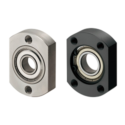 Bearing housings / compact flange / through holes / circlip / deep groove ball bearing / steel, stainless steel / black oxide, nickel plated
MISUMI Standard Price : 19.07 € Shipping Days: Same day


MISUMI Unit еxample related to this product


Tech Support
- Technical Support
- Tel:+49 69 668173-0 / FAX:+49 69 668173-360
- Technical Inquiry
Payment Method


On-Demand Manufacturing
Certificates


Copyright © MISUMI Corporation All Rights Reserved.