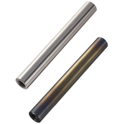
Linear shafts / double-sided internal thread (SFJW20-375-M10-N10)

Product Details:
Manufacturer part number: SFJW20-375-M10-N10
Brand: MISUMI
Price: Please contact the support for quotation
Delivery time: 4 Days
Technical Data:
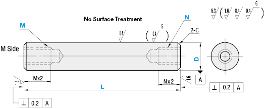
[D] Diameter (Shaft): 20 mm
[L] Length (Shaft): 375 mm
Material: [Alloyed Steel] EN 1.3505 Equiv.
Heat Treatment: Induction Hardened
Surface Treatment: No Treatment
- Order quantities extended (D-JIT)
(i)Remark
- SFJW has been localized according to European needs and requirements. Please have a look on the EU version SFJWEU. SFJWEU is available in EN 1.1213 (Cf53) and h6 / h7.
Part Number
Once your search is narrowed to one product,
the corresponding part number is displayed here.
SFJW20-375-M10-N10
- Drawing / Specifications
- 3D Preview 3D preview is available after complete configuration
- Part Numbers
- More Information
- Catalog
- Technical Information

| Type | Material | Hardness | Surface Treatment | ||
| D Tol. g6 | D Tol. h5 | D Tol. f8 | |||
| SFJW | SFUW | - | EN 1.3505 Equiv. | Effective Hardened Depth of Induction Hardening >>P.112 EN 1.3505 Equiv. 58HRC~ EN 1.4125 Equiv. 56HRC~ | - |
| SSFJW | SSFUW | - | EN 1.4125 Equiv. | ||
| PSFJW | PSFUW | - | EN 1.3505 Equiv. | Hard Chrome Plating Plating Hardness: HV750 ~ Plating Thickness: 5µ or More | |
| PSSFJW | PSSFUW | - | EN 1.4125 Equiv. | ||
| RSFJW | - | - | EN 1.3505 Equiv. | LTBC Plating | |
| - | - | PSFGW | EN 1.1191 Equiv. | - | Hard Chrome Plating Plating Hardness: HV750 ~ Plating Thickness: 10µ or More |
| - | - | PSSFGW | EN 1.4301 Equiv. | ||
Further specifications can be found under the tab More Information.
| Part Number | - | L | - | M | - | N |
| SFJW8 SSFJW20 | - - | 200 500 | - - | M4 M6 | - - | N4 N10 |

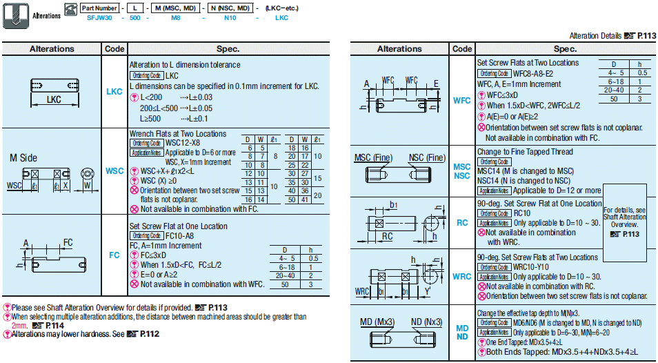
You find further options in detail under Option Overview.
Part Number:
- In order to open the 3D preview, the part number must be fixed.
3D preview is not available, because the part number has not yet been determined.
Part Number
|
|---|
| SFJW20-375-M10-N10 |
| Part Number | Minimum order quantity | Volume Discount | RoHS | [D] Diameter (Shaft) (mm) | [L] Length (Shaft) (mm) | Material | Heat Treatment | Surface Treatment | ISO Tolerance | Hardness | [M] Size (thread - depth 2xM) (mm) | [MD] Size (thread - depth 3xM) (mm) | [MSC] Size (fine thread - depth 2xMSC) (mm) | [N] Size (thread - depth 2xN) (mm) | [ND] Size (thread - depth 3xN) (mm) | [NSC] Size (fine thread - depth 2xN) (mm) | |
|---|---|---|---|---|---|---|---|---|---|---|---|---|---|---|---|---|---|
| 1 | 4 Days | 10 | 20 | 375 | [Alloyed Steel] EN 1.3505 Equiv. | Induction Hardened | No Treatment | g6 | Induction Hardening (58HRC~) | 10 | - | - | 10 | - | - |
Loading...

Overview of the shaft designs as PDF
| Part Number | L specified in 1mm Increment | M (Coarse), N (Coarse) Selection | D Tol. | C | ||||||||||||||||
| Type | D | g6 | h5 | f8 | ||||||||||||||||
| (D Tolerance g6) SFJW SSFJW PSFJW PSSFJW (D Tolerance f8) PSFGW PSSFGW | (D Tolerance h5) SFUW SSFUW PSFUW PSSFUW | 4 | 20~ 300 | 2 | -0.004 -0.012 | 0 -0.005 | - | 0.2 or Less | ||||||||||||
| 5 | 20~ 400 | 2.6 | 3 | -0.004 -0.012 | 0 -0.005 | - | 0.2 or Less | |||||||||||||
| 6 | 20~ 600 | 3 | -0.004 -0.012 | 0 -0.005 | -0.010 -0.028 | 0.5 or Less | ||||||||||||||
| 8 | 20~ 800 | 3 | 4 | 5 | -0.005 -0.014 | 0 -0.006 | -0.013 -0.035 | 0.5 or Less | ||||||||||||
| 10 | 20~ 800 | 3 | 4 | 5 | 6 | -0.005 -0.014 | 0 -0.006 | -0.013 -0.035 | 0.5 or Less | |||||||||||
| 12 | 20~1000 | 4 | 5 | 6 | 8 | -0.006 -0.017 | 0 -0.008 | -0.016 -0.043 | 0.5 or Less | |||||||||||
| 13 | 25~1000 | 4 | 5 | 6 | 8 | -0.006 -0.017 | 0 -0.008 | -0.016 -0.043 | 0.5 or Less | |||||||||||
| 15 | 25~1000 | 4 | 5 | 6 | 8 | 10 | -0.006 -0.017 | 0 -0.008 | -0.016 -0.043 | 0.5 or Less | ||||||||||
| 16 | 30~1200 | 4 | 5 | 6 | 8 | 10 | -0.006 -0.017 | 0 -0.008 | -0.016 -0.043 | 0.5 or Less | ||||||||||
| 18 | 30~1200 | 4 | 5 | 6 | 8 | 10 | 12 | -0.006 -0.017 | 0 -0.008 | -0.016 -0.043 | 0.5 or Less | |||||||||
| 20 | 30~1200 | 4 | 5 | 6 | 8 | 10 | 12 | -0.007 -0.020 | 0 -0.009 | -0.020 -0.053 | 1.0 or Less | |||||||||
| 25 | 35~1200 | 4 | 5 | 6 | 8 | 10 | 12 | 16 | -0.007 -0.020 | 0 -0.009 | -0.020 -0.053 | 1.0 or Less | ||||||||
| 30 | 35~1500 | 6 | 8 | 10 | 12 | 16 | 20 | -0.007 -0.020 | 0 -0.009 | -0.020 -0.053 | 1.0 or Less | |||||||||
| 35 | 35~1500 | 8 | 10 | 12 | 16 | 20 | 24 | -0.009 -0.025 | 0 -0.011 | -0.025 -0.064 | 1.0 or Less | |||||||||
| 40 | 50~1500 | 10 | 12 | 16 | 20 | 24 | 30 | -0.009 -0.025 | 0 -0.011 | -0.025 -0.064 | 1.0 or Less | |||||||||
| 50 | 65~1500 | 12 | 16 | 20 | 24 | 30 | -0.009 -0.025 | 0 -0.011 | -0.025 -0.064 | 1.0 or Less | ||||||||||
| Part Number | L specified in 1mm Increment | M (Coarse), N (Coarse) Selection | D Tol. | C | |||||||||||
| Type | D | g6 | |||||||||||||
| (D Tolerance g6) LTBC Plating RSFJW | 4 | 20~300 | 2 | -0.004 -0.012 | 0.2 or Less | ||||||||||
| 5 | 20~400 | 2.6 | 3 | -0.004 -0.012 | 0.2 or Less | ||||||||||
| 6 | 20~500 | 3 | -0.004 -0.012 | 0.5 or Less | |||||||||||
| 8 | 20~500 | 3 | 4 | 5 | -0.005 -0.014 | 0.5 or Less | |||||||||
| 10 | 20~500 | 3 | 4 | 5 | 6 | -0.005 -0.014 | 0.5 or Less | ||||||||
| 12 | 20~500 | 4 | 5 | 6 | 8 | -0.006 -0.017 | 0.5 or Less | ||||||||
| 13 | 25~500 | 4 | 5 | 6 | 8 | -0.006 -0.017 | 0.5 or Less | ||||||||
| 15 | 25~500 | 4 | 5 | 6 | 8 | 10 | -0.006 -0.017 | 0.5 or Less | |||||||
| 16 | 30~500 | 4 | 5 | 6 | 8 | 10 | -0.006 -0.017 | 0.5 or Less | |||||||
| 18 | 30~500 | 4 | 5 | 6 | 8 | 10 | 12 | -0.006 -0.017 | 0.5 or Less | ||||||
| 20 | 30~500 | 4 | 5 | 6 | 8 | 10 | 12 | -0.007 -0.020 | 1.0 or Less | ||||||
| 25 | 35~500 | 4 | 5 | 6 | 8 | 10 | 12 | 16 | -0.007 -0.020 | 1.0 or Less | |||||
| 30 | 35~500 | 6 | 8 | 10 | 12 | 16 | 20 | -0.007 -0.020 | 1.0 or Less | ||||||

You find further options in detail under Option Overview.
Basic information
| Basic Shape | Solid | Shaft end Shape (Left) | Internal thread | Shaft end Shape (Right) | Internal thread |
|---|---|---|---|---|---|
| Shaft end Perpendicularity | 0.2 |
Configure
Basic Attributes
-
[D] Diameter (Shaft)(mm)
-
Material
- Unalloyed Steel
- Stainless Steel (austenitic)
- Alloyed Steel
- Stainless Steel (martensitique)
- Unalloyed Steel
-
Heat Treatment
- No Treatment
- Induction Hardened
-
Surface Treatment
- No Treatment
- Hard Chrome Plating
- LTBC Plating
-
ISO Tolerance
-
Hardness
- Induction Hardening (56HRC~)
- Induction Hardening (58HRC~)
- No Induction Hardening
-
[MD] Size (thread - depth 3xM)(mm)
-
[MSC] Size (fine thread - depth 2xMSC)(mm)
-
[ND] Size (thread - depth 3xN)(mm)
-
[NSC] Size (fine thread - depth 2xN)(mm)
-
Type
- PSFGW
- PSFJW
- PSFUW
- PSSFGW
- PSSFJW
- PSSFUW
- RSFJW
- SFJW
- SFUW
- SSFJW
- SSFUW
-
[L] Length (Shaft)(mm)
-
[M] Size (thread - depth 2xM)(mm)
-
[N] Size (thread - depth 2xN)(mm)
-
Filter by CAD data type
- 2D
- 3D
Filter by standard shipping days
-
- All
- 4 Days or Less
- 6 Days or Less
- 7 Days or Less
- 8 Days or Less
- 10 Days or Less
- 12 Days or Less
Optional Attributes
- The specifications and dimensions of some parts may not be fully covered. For exact details, refer to manufacturer catalogs .
Frequently Asked Questions (FAQ)
-
Question:
What is the difference between a hollow shaft and a solid shaft?
-
Answer:
With the same size, there are three differences between a hollow shaft and a solid shaft. Hollow shafts weigh less. The inner cavity of a hollow shaft is suitable for use as a channel (cable channel). Solid shafts are a bit more rigid (higher resistance torque).
-
Question:
What is the minimum order of linear shafts from MISUMI?
-
Answer:
MISUMI supplies solid shafts, hollow shafts and precision shafts starting at a lot size of 1. This also applies to all other items in our product range.
-
Question:
Noises and vibrations occur with a linear shaft. In addition, there are jerky movements. What could cause this?
-
Answer:
In general, it may be caused if the steel shaft is not properly lubricated. In addition, an incorrectly selected diameter tolerance of the linear shafts may also make the cycle of motion more difficult. When using MISUMI linear ball bearings, a g6 shaft tolerance is recommended (tolerance recommendations may vary depending on the manufacturer).
-
Question:
What is the strength of a solid shaft?
-
Answer:
The strength of a linear shaft, although it is a solid shaft, hollow shaft or precision shaft, should always be selected in consideration of the strength of the material used.
-
Question:
What are the advantages of a hollow shaft over a solid shaft?
-
Answer:
There are various advantages of a hollow shaft compared to a solid shaft. If the outer diameter is the same, the weight of a hollow shaft is lower than that of a solid shaft. However, the cavity of the hollow shaft can also be used as a cable channel or for cooling. A hollow shaft is at the same weight or with the same cross-sectional area more rigid than a solid shaft, because the outer diameter is larger. However, the question that needs to be answered is whether the advantage is a greater room utilization or less weight.
-
Question:
Is a hollow shaft stiffer than a solid shaft?
-
Answer:
The rigidity of a hollow shaft is slightly lower with the same outer diameter than that of a solid shaft. However, with the same cross-sectional area or with the same weight, the stiffness of a hollow shaft is higher than that of a solid shaft, because the outer diameter of the hollow shaft is larger.
-
Question:
Why do I have running grooves on the linear shafts of my 3D printers?
-
Answer:
The running grooves on the linear shaft may have been created, for example, by using a linear ball bearing. To prevent grooves from forming on a steel shaft, it should be hardened and hard chromium plated, making it more durable and resistant to the wear and tear from ball bearings.
-
Question:
How do the flexure properties of hollow shafts and solid shafts differ?
-
Answer:
With an equally large outer diameter, a solid shaft has better flexure properties than an equally large hollow shaft. However, the solid shaft is not much stiffer than a hollow shaft with the same outer diameter, since the outer sections mainly carry the load. Hollow shafts with the same cross-sectional area are more rigid than solid shafts, because they have a larger outer diameter. Therefore, there is physically more material in the outer sections for the bending, which bears the loads.
-
Question:
I need a lacquered or matted shaft because reflections cause problems with the optics. Does MISUMI have something like that?
-
Answer:
MISUMI LTBC-coated linear shafts are an alternative to painted or matted steel shafts. The LTBC coating is low-reflection and has the same effect as painted and matte shafts. In addition, LTBC-coated linear shafts are more resistant to wear and tear and flaking. You can find further information on LTBC coating here .
-
Question:
It has been shown that a hollow shaft is stronger than a solid shaft made of the same material. Why?
-
Answer:
A hollow shaft with the same outer dimensions is principally not stronger than a solid shaft. However, a hollow shaft per weight unit is stronger.


