
- inCAD Library Home
- > No.000050 Adjustment Mechanism
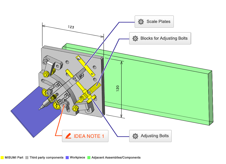
No.000050 Adjustment Mechanism
49
Adjusting the angle at the offset center point
Related Category


Adjusting Bolts
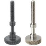
| Product name | Adjusting Bolts/Knurled Knobs |
|---|---|
| Part number | AJSTKS6-50 |
Selection criteria
Effective for Precise Adjustment Manually
Available sizes
■Adjusting Bolts, Knurled Knobs
| Screw Type | Material | Surface Treatment |
|---|---|---|
| Coarse Thread | EN 1.1191 Equiv. | Black Oxide |
| Electroless Nickel Plating | ||
| EN 1.4301 Equiv. | - |
■Sizes and Dimensions
| Screw Dia. (coarse) | Thread Length (5mm increments) | Block Bearing Part | Knob | ||
|---|---|---|---|---|---|
| Diameter | Length | Thickness | O.D. | ||
| M3 | 10 ~ 20 | Ø2.5 | 7 | 4 | Ø16 |
| M4 | 10 ~ 30 | Ø3.5 | |||
| M5 | 10 ~ 40 | Ø4.5 | 9 | 6 | Ø20 |
| M6 | 15 ~ 50 | Ø5.5 | |||
| M8 | 20 ~ 50 | Ø7.5 | 12 | ||
Accuracy Info
■Accuracy of the Adjusting Bolts
Block Support
Shaft Dia. Tolerance: -0.1/-0.2
Length Tolerance: +0.2/+0.1
Surface Roughness: Ra1.6

Blocks for Adjusting Bolts
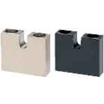
| Product name | Blocks for Adjusting Bolts/Standard Type |
|---|---|
| Part number | AJKCM6-30 |
Selection criteria
Effective for Precise Adjustment Manually
Available sizes
■Blocks for Adjusting Bolts, H Selectable
| Screw Type | Material | Surface Treatment |
|---|---|---|
| Coarse Thread | EN 1.1191 Equiv. | Black Oxide |
| Electroless Nickel Plating | ||
| EN 1.4301 Equiv. | - |
■Sizes and Dimensions
| (applicable bolt screw dia.) | Bolt Bearing Slot Width | Center Height [H] | Overall Height ([H] + listed below) | Overall Thickness | Overall Width | ||||||||
|---|---|---|---|---|---|---|---|---|---|---|---|---|---|
| 5 | 6 | 8 | 10 | 12 | 15 | 20 | 25 | 30 | |||||
| M3 | 2.5 | ○ | ○ | ○ | 5 | 7 | 26 | ||||||
| M4 | 3.5 | ○ | ○ | ○ | ○ | ||||||||
| M5 | 4.5 | ○ | ○ | ○ | ○ | ○ | 6 | 9 | 32 | ||||
| M6 | 5.5 | ○ | ○ | ○ | ○ | ○ | ○ | ||||||
| M8 | 7.5 | ○ | ○ | ○ | ○ | ○ | 8 | 12 | 38 | ||||
| M10 | 9.5 | ○ | ○ | ○ | ○ | ○ | 10 | 16 | 50 | ||||
| M12 | 11.5 | ○ | ○ | ○ | ○ | ○ | 11 | 19 | 65 | ||||
| M16 | 15.5 | ○ | ○ | ○ | ○ | ||||||||
Accuracy Info
■Accuracy of Blocks for Adjusting Bolts
Slot Width Tolerance: +0.1/0
Overall Thickness Tolerance: 0/-0.2

Scale Plates
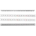
| Product name | Scale Plates |
|---|---|
| Part number | MEPCSH-LC48-HC |
Selection criteria
Because a scaled plate is available without having to perform troublesome tasks as preparation works on a plate
Available sizes
■Scale Plates (Horizontal,EN 1.4301 Equiv.)
| Width | Scale Type | Material | Plate Thickness | Length |
|---|---|---|---|---|
| 8 | Zero at Left | EN 1.4301 Equiv. | 0.5 | 100 ・ 200 |
| Zero at Right | 100 ・ 200 | |||
| Center Divided | 300 | |||
| 12 | Zero at Left | 100 ・ 200 | ||
| Zero at Right | 100 ・ 200 | |||
| Center Divided | 300 |
* Adhesive tapes are not provided.
Use the Ø3.4 x 2 screw mounting holes (5mm from the both ends).
* Length cut is available as alterations.

-
 Terms of use of CAD data and simplified drawing data
- These terms and conditions (hereinafter referred to as “the Terms") set forth the conditions for downloading CAD data and simplified drawing data provided by MISUMI Corporation (hereinafter referred to as "MISUMI") via www.misumi-europe.com operated by MISUMI Europa GmbH(hereinafter referred to as the "Website"). By downloading CAD data and simplified drawing data posted on the Website (hereafter referred to as “Data”), customers are deemed to have agreed to these Terms.
- 1. Purpose of Use
-
MISUMI offers the following:
1)CAD data found on the Website (3D CAD data, 3D Intermediate data and 2D CAD data) for the purpose of informing customers of the characteristics of the products offered by MISUMI or a manufacturer affiliated with MISUMI for use in their designs.
2)Simplified drawing data (in PDF format) for the purpose of checking the specifications of products. - 2. Characteristics of Data
- There may be a discrepancy in certain characteristics of products (for example: tolerance, surface roughness, chamfer, etc.) between the Data and the actual product. Furthermore, for the purpose of reducing the file size of the Data, some information such as oil groove shapes, threads, or spring shapes, may be removed from the Data.
- 3. Disclaimer
- MISUMI carefully creates the Data but makes no warranty as to the quality, accuracy, functionality, safety, reliability, etc., of the Data. MISUMI may at any time, and with no prior notice to customers, revise or delete Data. MISUMI assumes no responsibility for any damage or loss resulting from any revision or deletion of the Data, or any errors in said data. Customers are solely responsible for all aspects of their own designs, including those made using the Data. MISUMI may provide customers with design example data on the Website, but the quality, accuracy, functionality, safety, reliability, etc., of such data are not guaranteed. MISUMI may, at any time, and in its sole discretion, request that the customer cease its use of or destroy the Data in its possession. MISUMI may request the customer provide MISUMI documentation of such destruction.
- 4.Prohibited Acts
-
Customers or users of the Data, are prohibited from the following acts regarding the Data, in whole or in part:
(1)Requesting quotations or placing orders for products with third parties other than those authorized by MISUMI or its affiliates;
(2)Receiving quotations or orders for products from third parties by providing the Data to a third party or using the Data in their own business;
(3)Displaying links to the Website related to the Data on their own websites, etc., without consent of MISUMI or its affiliates;
(4)Using or reproducing the Data beyond the scope of the above-stated Purpose of Use;
(5)Modifying, altering, tampering with, translating, or adapting the Data;
(6)Selling, transferring, lending, sublicensing, or providing the Data to third parties in any way without consent of MISUMI or its affiliates;
(7)Altering the content, reverse engineering, decompiling, disassembling, or analyzing the Data;
(8)Publicly disclosing or exhibiting the Data without consent of MISUMI or its affiliates;
(9)Using the Data for the purpose of providing products and services identical or similar to those of MISUMI or its affiliates;
(10)Performing acts that interfere with the proper functioning of this Website, such as acquiring Data in bulk. - 5. Copyright
-
All title and copyright in and to any information contained in the Data are owned by MISUMI or the relevant manufacturer affiliated with MISUMI and are protected by applicable copyright laws and international treaties. By downloading Data, the customer acquires no ownership rights of any kind in the intellectual property contained within. Without prior approval from MISUMI, no part of the Data may be utilized (reproduced, modified, reverse-engineered, uploaded, presented, sent, distributed, licensed, sold, or published) for any purpose other than that mentioned above.
In the event Data is found to have been to be used for any purpose other than that mentioned above or against any applicable laws or the Terms, MISUMI may pursue any legal remedy available to it, which may result in forbidding the offending user from using the Data or accessing the Website. - 6. Third-Party Data
- MISUMI offers some Data provided by third parties. Such Data may be subject to separate terms and conditions, in addition to these terms. MISUMI makes no guarantee or warranty regarding Data from third parties.
- 7. Export Control
- Customers shall comply with all applicable laws and regulations regarding the export of the Data.
- 8. Amendments to the Terms
- MISUMI may, at any time, and in its sole discretion, modify these terms and conditions; any such modification will be effective immediately.
- 9. Severability
- If any term or provision of these Terms is invalid, illegal, or unenforceable in any jurisdiction, such invalidity, illegality, or unenforceability shall not affect any other term or provision of these Terms or invalidate or render unenforceable such term or provision in any other jurisdiction. Section 139 BGB (German Civil Code) shall not apply.
- 10.Miscellaneous
-
In the event that Customers violate the Terms, MISUMI and/or MISUMI Europa GmbH shall be entitled to claim the damages and expenses (including attorney's fees) incurred by such violation against the Customers.
These Terms and any disputes arising in connection therewith shall be exclusively governed by and construed in accordance with the laws of the Federal Republic of Germany, without regard to its conflicts of law principles. The courts located in Frankfurt am Main/Germany shall have exclusive jurisdiction to adjudicate any dispute arising in connection with these Terms. By downloading the Data, you agree to submit to the exclusive and personal jurisdiction of the courts located in Frankfurt am Main/Germany. - Revised: September 21, 2025
CAD Data Download (Unit Assembly)
CAD Data Download: File Format
Cautions on the CAD data
-
Assembly data shows the assembly drawings in the concept design phase. The sole purpose of the data is to explain the structure and functionality of the assembly and is not considered nor to be used as a final design.
You will need to edit the Data so that it meets your specific design conditions. -
The CAD data unit assembly consists of sub-assemblies.
Each sub-assembly unit can be used as it is or can be edited. - The Data for fabricated parts is based on easy-to-edit dimensions and shapes in sketches and histories.
- The Data including the third-part components are made by the Company.
* The part in the frame is a sub-assembly unit.
-

- * Unit assembly CAD data consists of some sub-assemblies.
Each sub-assembly unit can be used as it is or can be edited.
Application Overview
Purpose
- Purpose
- To be mounted on a loader, etc., and to adjust the inclination angle of a dispenser for adhesive application.
- Operation
- By loosening the rotary plate fixing bolt and turning the adjusting bolt, the inclination angle of the dispenser is adjusted.
Points for use
- Manual angle adjustment.
Target workpiece
- Shape: circuit board
- Size: W65 x D20 x t1.6mm
- Weight:5g
Design Specifications
Operating Conditions or Design Requirements
- Dispenser inclination angle adjustment: 45°±8° (37° to 53°)
- Outer dimensions: W123 x D120 x H56mm
Required Performance
- Depends on the positioning accuracy of the loader, etc.
Selection Criteria for Main Components
- Cam Follower
- A cam follower (CFFRS6-16) that has an outer ring thickness suitable for pressing the rotary plate (thickness: 13mm) and a size small enough to be mounted on this mechanism is selected.
Design Evaluation
Verification of main components
- Verify that the rotary arm and adjusting bolt can create the required inclination angle resolution.
- Calculation of resolution of angle adjustment mechanism.
- Conditional value: adjustable angle θ = 8°, adjusting bolt thread diameter M6, pitch of M6 thread P = 1mm, movable range of adjusting nut L = 16.4mm, distance between rotation center of rotary arm and adjusting bolt (rotary arm length) R = 117mm
- As the resolution at center of adjustment range: Δθ1, and the travel distance per rotation of adjusting bolt = pitch of M6 thread P = 1, sinΔθ1 = P/R = 1
Δθ1 = sin-1(P/R) = sin-1(1/117) = 0.490°/rotation - Where resolution at adjustment range limit: Δθ2, angle formed by rotary arm and adjustment range center : α, distance between adjusting nut and adjustment range center: L = 16.4, angle at center formed by rotary arm adjustment range center and arm travel made when adjusting bolt is rotated one revolution: β, as α - β = Δθ2 and sinα = L/R, sinβ = (L - P)/R,
Δθ2 = α - β = sin-1(L/R) - sin-1((L - P)/R) = sin-1(16.4/117) - sin-1((16.4 - 1)/117) = 8.0578 - 7.5634 = 0.494°/rotation
Other Design Consideration
- Applying a preload to the cam follower on the pushing side ensures the adjustment mechanism will not have backlash in the radial direction.
Explore Similar Application Examples


Payment Method


On-Demand Manufacturing
Certificates


Copyright © MISUMI Corporation All Rights Reserved.