Linear Guides for Heavy Load
Product name | Linear Guide Blocks/Heavy Load/With Resin Retainer |
Part number | SXWZ28-400 |
Features | With No Mutual Ball Contacts, Resin Retainer provides Low-Noise and Smooth Movements. |
* Orange colored cells in the table below indicate the part numbers used in this example.
Selection criteria
Rail Strength
Back to page top
Available sizes
■Linear Guides for Heavy Load, With Resin Retainer, Interchangeable, Light Preload
Type | Number of Blocks | Material | Hardness |
Standard | 1 ・ 2 | Carbon Steel | 58HRC ~ |
Wide Block Through Hole |
Wide Block Tapped Hole |
■Sizes and Dimensions
Block Type | Overall Height | Rail Length (Configure in 1 mm increments) | Block Dimension | Rail Width |
1 blocks | 2 blocks | Width | Length |
1 blocks | 2 blocks |
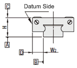
Standard | 24 | 100 ~ 1480 | 160 ~ 1480 | 34 | 56.8 | 56.8 x 2 pcs. | 15 |
28 | 160 ~ 1960 | 220 ~ 1960 | 42 | 65.2 | 65.2 x 2 pcs. | 20 |
33 | 160 ~ 1960 | 220 ~ 1960 | 48 | 81.6 | 81.6 x 2pcs. | 23 |
42 | 200 ~ 1960 | 280 ~ 1960 | 60 | 96.4 | 96.4 x 2pcs. | 28 |
Wide Block | 24 | 100 ~ 1480 | 160 ~ 1480 | 52 | 56.8 | 56.8 x 2 pcs. | 15 |
28 | 160 ~ 1960 | 220 ~ 1960 | 59 | 65.2 | 65.2 x 2 pcs. | 20 |
33 | 160 ~ 1960 | 220 ~ 1960 | 73 | 81.6 | 81.6 x 2 pcs. | 23 |
42 | 200 ~ 1960 | 280 ~ 1960 | 90 | 96.4 | 96.4 x 2 pcs. | 28 |
Back to page top
Selection Steps
■Linear guide selection steps
- Determine Application Conditions
- (Moving mass, feed rate, motion pattern, life)
↓
- Temporarily select linear bushing specifications
- (Block type, overall height, rail length are temporarily selected according to the conditions of use.)
↓
- Basic safety check
-
- ●Allowable Load
- ●Operating Life
- ●Preload
Back to page top
Accuracy Info
■Preload and Accuracy Standard (Heavy Load Linear Guide With Plastic Retainers, Interchangeable, Light Preload)
(μm)
Radial Clearance | -4 ~ 0(H24 ・ 8) |
-5 ~ 0(H33 ・ 42) |
H Dimension Tolerance | ±20 |
Pair variation of H | 15 |
Tolerance of dims. W2 | ±30 |
Pair variation of W2 | 25 |
(μm)
| Rail Length (mm) |
-80 | 81-125 | 126-200 | 201-250 | 251-315 | 316-400 | 401-500 | 501-630 | 631-800 | 801-1000 | 1001-1250 | 1251-1600 | 1601-2000 |
Running Parallelism | 6 | 6.5 | 7 | 8 | 9 | 11 | 12 | 14 | 16 | 18 | 20 | 23 | 26 |
Back to page top
Performance info.
■Rated Load of Linear Guide (Heavy Load Linear Guide With Plastic Retainers, Interchangeable, Light Preload)
Overall Height | Basic Load Rating | Allowable Static Moment |
C (Dynamic) kN | Co (Static) kN | MA N ・ m | MB N ・ m | Mc N ・ m |
24 | 7.9 | 15.6 | 74 | 62 | 78 |
28 | 11.1 | 21.8 | 124 | 104 | 149 |
33 | 17.9 | 33.5 | 242 | 203 | 266 |
42 | 27.3 | 50.5 | 415 | 305 | 480 |
Back to page top
Technical Calculations
■Linear guide life calculations
- ●Life
- When the linear system is in motion with applied load, the rolling surfaces and races are subject to repeated stress. This stress can cause scale-like flaking due to material fatigue. The total run distance until the flaking appears is the "Life" of the linear system.
- ●Rated Life
- Rated life is a total distance 90% of linear guides reach without flaking when a group of the same guides are run under the same condition. The rated life can be calculated with basic dynamic load rating and the load applied on the guides as follows.
-
- Load must be calculated before actually using linear guides. To obtain loads during linear reciprocating motion, it is necessary to consider vibrations and impacts during motion as well as the distribution load applied to the linear guides.The operating environment temperature also effects the life of these parts. When taking these conditions into consideration, the calculation will be:
-
- L: Rated Life (Km)
- fH: Hardness Factor (See Fig.1)
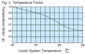
- fT: Temperature Factor (See Fig.2)
- fC: Contact Factor (See Table-1)
- fW: Load Factor (See Table-2)
- C: Basic Dynamic Load Rating (N)
- P: Applied Load (N)
- ●Hardness factor (fH)
-
For linear applications, the rail and ball bearings must have sufficient hardness. If they do not, the load rating decreases and the life will be reduced.
- ●Temperature factor (fT)
-
When the temperature of the linear system exceeds 100 degrees C, the hardness will decrease and as a result, the allowable load and life will be reduced.
* Please use linear guides within the resistant temperature range on the product pages.
- ●Contact factor (fC)
-
Table-1. Contact Factor
Number of blocks per rail Contact factor fC
1 | 1.00 |
2 | 0.81 |
3 | 0.72 |
4 | 0.66 |
5 | 0.61 |
In general, it is common to use two or more blocks on one rail. In these cases, the load on each block will vary depending on the machining precision and will not have equally distributed loads. As a result, the allowable load per block will vary depending on the number of blocks used on the rail.
- ●Load Factor (fW)
-
Table-2. Load Factor
Condition of Use | fw |
No external shocks or vibrations and speed is low 15m/min or less | 1.0-1.5 |
No significant shocks or vibration and med. speed 60m/min or less | 1.5-20 |
External shocks and vibrations exist and the speed is high 60m/min or over | 2.0-3.5 |
To calculate the load applied to the linear guides, in addition to the object weight, the inertia force attributed to the motion velocity, moment loads and the variations of each over time must be obtained. However, for reciprocating motion applications, it is difficult to obtain accurate calculations due to effects of the vibrations and shocks. therefor, use Table 2 to simplify the life calculations.
- ●Applied Load P Calculation Method
- When moment loads apply a block, use the following formula to convert the moment load to applicable load.
-
- P: Applied Load (N)
- F: Downward load (N)
- Co: Static load rating (N)
- MA: Allowable Static Moment - Pitching Direction (N・m)
- MC: Allowable Static Moment - Rolling Direction (N・m)
- Lp: Load point distance (m) in pitching direction
- Lr: Load point distance (m) in rolling direction
Back to page top
Floating Joint
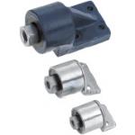
Product name | Floating Connectors/Bracket Mouning Type |
Part number | FLCL10-1.25 |
Features | Floating Joint can be installed vertically |
* Orange colored cells in the table below indicate the part numbers used in this example.
Selection criteria
Bracket mounting type required for this application
Back to page top
Available sizes
■Floating Joint - Bracket Mounting Type
Part Name | Material | Surface Treatment |
Main Body | Steel Ball Retainer Plate | Nitrile Rubber | - |
Rod Tip Socket | EN 1.0038 Equiv. | Trivalent Chromate |
Cap | EN 1.3505 Equiv. |
Steel Ball Retainer |
Ball Holder |
Case | EN-JL 1030 Equiv. |
Thread | EN 1.0038 Equiv. |
Mounting Part | (M8 ~ M12) | EN 1.0330 Equiv. |
(M14 ~ M26) | EN-JL 1030 Equiv. | Enamel Paint (Blue) |
■Sizes and Dimensions
Thread Dia. - Pitch | Overall Length | Main Body Outer Dia. | Overall Width | Core Height | Allowable Misalignment |
M8-1.0 | 49.5 | Ø30 | 31 | 16 | 0.5 |
M10-1.25 | 61.5 | Ø36 | 43 | 19 | 0.75 |
M12-1.5 |
M14-1.5 | 110 | Ø51 | 51 | 26 | 1 |
M16-1.5 |
M18-1.5 | 120 |
M22-1.5 | 145 | Ø62 | 62 | 32 | 1.5 |
M26-1.5 | 173 | Ø69 | 69 | 37 |
Back to page top
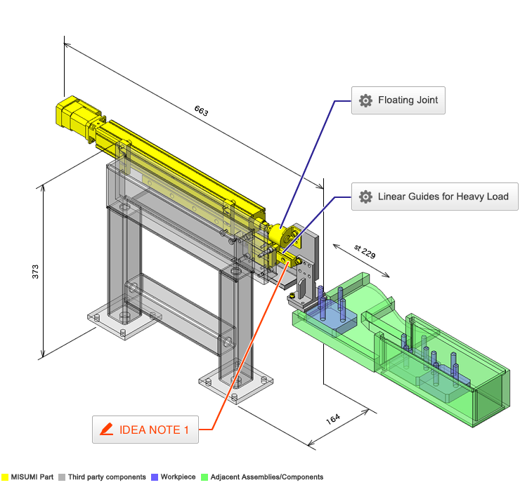
IDEA NOTE The linear block is fixed and rail is in motion.
For the movement of the block, a rail needs to be installed in the block's movement range. The rail cannot be installed due to the restriction imposed by the workpiece on the transfer table. (The height of the device is limited to 380 mm or less, making it impossible to avoid interference using the vertical space.) To counter this restriction, the block is fixed and the rail moves.