
- inCAD Library Home
- > No.000128 Sorting Mechanism
No.000128 Sorting Mechanism
15
Reduce cycle time by utilizing right/left sorting mechanism
Related Category


Single Axis Robot
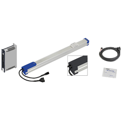
| Product name | Single Axis Robots RS2/Linear |
|---|---|
| Part number | RS220-C1-C-3-150 |
Selection criteria
Robot is selected to minimize jerk during transporting.
Available sizes
■Single axis robot (RS, slider type, No brake)
■General specifications
| Ball screw | Motor | Position detector | Operating environment temp - Humidity | Controller input power supply |
|---|---|---|---|---|
| Ø8 (C10 Rolled) | Stepping | Resolver (Incremental) | 0 ~ 40°C ・ 35 ~ 85%RH (No condensation) | DC24V±10% |
| Ø12 (C10 Rolled) |
Basic specifications
| Slider Upper Surface Height (mm) | Type | Lead (mm) | Stroke (mm) |
|---|---|---|---|
| 51 | RS1 | 2 | 50 ~ 400 (Increment of 50) |
| 6 | |||
| 12 | |||
| 57 | RS2 | 6 | 50 ~ 800 (Increment of 50) |
| 12 | |||
| 20 | |||
| 60 | RS3 | 6 | 50 ~ 800 (Increment of 50) |
| 12 | |||
| 20 |
Selection steps
■Single axis robot selection steps
Load capacity
↓
Stroke
↓
Cycle time or Max. Speed
↓
Detail confirmation
Accuracy Info
■Single axis robot accuracy
Repeatability: ±0.02
Performance info.
■Single axis robot Performance info.
| Slider Upper Surface Height (mm) | Type | Lead (mm) | Load capacity (kg) | Max. push force | Allowable moment capacity (N・m) | Max speed (mm/sec) | Rated life | |||
|---|---|---|---|---|---|---|---|---|---|---|
| Horizontal | Vertical | (N) | Pitching | Yawing | Rolling | |||||
| 51 | RS1 | 2 | 6 | 4 | 150 | 19 | 16 | 17 | 100 | 10,000km or more |
| 6 | 4 | 2 | 90 | 300 | ||||||
| 12 | 2 | 1 | 45 | 600 | ||||||
| 57 | RS2 | 6 | 10 | 2 | 90 | 33 | 25 | 30 | 300 ~ 190 | 10,000km or more |
| 12 | 6 | 1 | 45 | 600 ~ 380 | ||||||
| 20 | 4 | - | 27 | 1000 ~ 633 | ||||||
| 60 | RS3 | 6 | 12 | 4 | 120 | 38 | 32 | 34 | 300 ~ 190 | 10,000km or more |
| 12 | 8 | 2 | 60 | 600 ~ 380 | ||||||
| 20 | 6 | - | 36 | 1000 ~ 633 | ||||||

Air Gripper
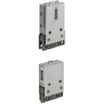
| Product name | Air Gripper/Parallel Type |
|---|---|
| Part number | ACHK6-N |
| Features | Compact Type Pneumatic Grippers with high precision, high rigidity, strong retaining force and. |
Selection criteria
Compact suitable for workpiece gripping.
Available sizes
■Small parallel air gripper (Integrated sensor)
| Part name | Material | Surface treatment |
|---|---|---|
| Main body | EN AW-5056 Equiv. | Clear anodize |
| Fingers ・ Attachment mount | EN 1.1191 Equiv. | Nitriding treatment |
■Specifications and Dimensions
| Operating method | Stroke | Cylinder I.D. | Overall width | Overall height | Thickness |
|---|---|---|---|---|---|
| Single Acting ・ Double Acting | 4 | Ø8 | 26 | 40.5 | 10 |
| 6 | Ø12 | 30 | 45 | 16.4 |
Selection steps
■Small parallel gripper selection steps
- Confirmation of Conditions
- (Confirming required stroke,weight, and shape)
↓
- Calculation of required gripping force
-
- 10 ~ 20 times of the workpiece weight required
- (Varies by friction coefficient of fingers and workpiece.)
↓
- Model Selection
-
- ●Gripping method (O.D. gripping ・ I.D. gripping)
- ●Open/close operation method (Single acting or Dual acting)
- ●Stroke
- ●Gripping points and gripping force
Performance info.
■Small parallel gripper (Integrated sensor) load info.
| Stroke | Cylinder I.D. | Operating pressure range | Effective gripping force (N) | Allowable static load (N) | ||
|---|---|---|---|---|---|---|
| Single acting (Spring) | Dual acting | F1 | F2 | |||
| 4 | Ø8 | 0.3 ~ 0.5MPa | 4.2 (1) | 4.9 | 5 | 2.5 |
| 6 | Ø12 | 10.4 (1.9) | 12.2 | 10 | 5 | |


Cable Carrier
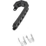
| Product name | Cable Carriers/Flap Open-Close Type (Cable Carrier+Mounting Brackets) |
|---|---|
| Part number | MHPUS202-45-12-A |
Selection criteria
To protect connection cables
Available sizes
■Cable carrier, Flap open/close type
| Main body | Mounting bracket | |
|---|---|---|
| Material | Material | Surface treatment |
| Nylon 6 + Glass Fiber 20% (Operating temp. -10 ~ 80°C) Flammability standards UL94-HB equivalent | Low Carbon Steel | Trivalent chromate |
■Sizes and Dimensions
| Name No. | Bend radius | Number of links | Mounting direction | Inner height | Mounting height | (Required space height) | |||||
|---|---|---|---|---|---|---|---|---|---|---|---|
| Inner height | Height | Inner width | Width | Link pitch | |||||||
| 102 | 19 | 5 ~ 23 | Mounting Direction S | 9 | 12 | 20 | 27 | 20 | 50 | 65 | |
| 202 | 25 | 6 ~ 34 | For Moving Ends: Mounting on the Outer Circumference For Both Moving and Fixed Ends: Common to the outer and inner circumferences | For Moving Ends: Mounting on the Inner Circumference For Both Moving and Fixed Ends: Common to the outer and inner circumferences | 14 | 20 | 14 | 26 | 25 | 70 | 85 |
| 30 | 6 ~ 34 | 80 | 95 | ||||||||
| 45 | 8 ~ 36 | 110 | 125 | ||||||||
| 203 | 30 | 6 ~ 34 | 14 | 20 | 20 | 32 | 25 | 80 | 95 | ||
| 45 | 8 ~ 36 | 110 | 125 | ||||||||
| 204 | 38 | 6 ~ 36 | 14 | 22 | 20 | 40 | 32 | 98 | 118 | ||
| 50 | 7 ~ 37 | 122 | 142 | ||||||||
| 206 | 38 | 6 ~ 36 | 14 | 22 | 40 | 60 | 32 | 98 | 118 | ||
| 50 | 7 ~ 37 | 122 | 142 | ||||||||
| 306 | 50 | 6 ~ 38 | For Moving Ends: Mounting on the Outer Circumference For Both Moving and Fixed Ends: Common to the outer and inner circumferences | For Moving Ends: Mounting on the Inner Circumference For Both Moving and Fixed Ends: Common to the outer and inner circumferences | 24 | 34 | 44 | 60 | 45 | 134 | 160 |
| 100 | 10 ~ 42 | 234 | 260 | ||||||||
| 408 | 50 | 6 ~ 38 | 24.5 | 40 | 58 | 78 | 45 | 140 | 170 | ||
| 75 | 8 ~ 40 | 190 | 220 | ||||||||
| 100 | 10 ~ 42 | 240 | 270 | ||||||||
| 150 | 13 ~ 45 | 340 | 370 | ||||||||
| 412 | 50 | 6 ~ 38 | 24.5 | 40 | 97 | 117 | 45 | 140 | 170 | ||
| 75 | 9 ~ 41 | 190 | 220 | ||||||||
| 100 | 10 ~ 42 | 240 | 270 | ||||||||


-
 Terms of use of CAD data and simplified drawing data
- These terms and conditions (hereinafter referred to as “the Terms") set forth the conditions for downloading CAD data and simplified drawing data provided by MISUMI Corporation (hereinafter referred to as "MISUMI") via www.misumi-europe.com operated by MISUMI Europa GmbH(hereinafter referred to as the "Website"). By downloading CAD data and simplified drawing data posted on the Website (hereafter referred to as “Data”), customers are deemed to have agreed to these Terms.
- 1. Purpose of Use
-
MISUMI offers the following:
1)CAD data found on the Website (3D CAD data, 3D Intermediate data and 2D CAD data) for the purpose of informing customers of the characteristics of the products offered by MISUMI or a manufacturer affiliated with MISUMI for use in their designs.
2)Simplified drawing data (in PDF format) for the purpose of checking the specifications of products. - 2. Characteristics of Data
- There may be a discrepancy in certain characteristics of products (for example: tolerance, surface roughness, chamfer, etc.) between the Data and the actual product. Furthermore, for the purpose of reducing the file size of the Data, some information such as oil groove shapes, threads, or spring shapes, may be removed from the Data.
- 3. Disclaimer
- MISUMI carefully creates the Data but makes no warranty as to the quality, accuracy, functionality, safety, reliability, etc., of the Data. MISUMI may at any time, and with no prior notice to customers, revise or delete Data. MISUMI assumes no responsibility for any damage or loss resulting from any revision or deletion of the Data, or any errors in said data. Customers are solely responsible for all aspects of their own designs, including those made using the Data. MISUMI may provide customers with design example data on the Website, but the quality, accuracy, functionality, safety, reliability, etc., of such data are not guaranteed. MISUMI may, at any time, and in its sole discretion, request that the customer cease its use of or destroy the Data in its possession. MISUMI may request the customer provide MISUMI documentation of such destruction.
- 4.Prohibited Acts
-
Customers or users of the Data, are prohibited from the following acts regarding the Data, in whole or in part:
(1)Requesting quotations or placing orders for products with third parties other than those authorized by MISUMI or its affiliates;
(2)Receiving quotations or orders for products from third parties by providing the Data to a third party or using the Data in their own business;
(3)Displaying links to the Website related to the Data on their own websites, etc., without consent of MISUMI or its affiliates;
(4)Using or reproducing the Data beyond the scope of the above-stated Purpose of Use;
(5)Modifying, altering, tampering with, translating, or adapting the Data;
(6)Selling, transferring, lending, sublicensing, or providing the Data to third parties in any way without consent of MISUMI or its affiliates;
(7)Altering the content, reverse engineering, decompiling, disassembling, or analyzing the Data;
(8)Publicly disclosing or exhibiting the Data without consent of MISUMI or its affiliates;
(9)Using the Data for the purpose of providing products and services identical or similar to those of MISUMI or its affiliates;
(10)Performing acts that interfere with the proper functioning of this Website, such as acquiring Data in bulk. - 5. Copyright
-
All title and copyright in and to any information contained in the Data are owned by MISUMI or the relevant manufacturer affiliated with MISUMI and are protected by applicable copyright laws and international treaties. By downloading Data, the customer acquires no ownership rights of any kind in the intellectual property contained within. Without prior approval from MISUMI, no part of the Data may be utilized (reproduced, modified, reverse-engineered, uploaded, presented, sent, distributed, licensed, sold, or published) for any purpose other than that mentioned above.
In the event Data is found to have been to be used for any purpose other than that mentioned above or against any applicable laws or the Terms, MISUMI may pursue any legal remedy available to it, which may result in forbidding the offending user from using the Data or accessing the Website. - 6. Third-Party Data
- MISUMI offers some Data provided by third parties. Such Data may be subject to separate terms and conditions, in addition to these terms. MISUMI makes no guarantee or warranty regarding Data from third parties.
- 7. Export Control
- Customers shall comply with all applicable laws and regulations regarding the export of the Data.
- 8. Amendments to the Terms
- MISUMI may, at any time, and in its sole discretion, modify these terms and conditions; any such modification will be effective immediately.
- 9. Severability
- If any term or provision of these Terms is invalid, illegal, or unenforceable in any jurisdiction, such invalidity, illegality, or unenforceability shall not affect any other term or provision of these Terms or invalidate or render unenforceable such term or provision in any other jurisdiction. Section 139 BGB (German Civil Code) shall not apply.
- 10.Miscellaneous
-
In the event that Customers violate the Terms, MISUMI and/or MISUMI Europa GmbH shall be entitled to claim the damages and expenses (including attorney's fees) incurred by such violation against the Customers.
These Terms and any disputes arising in connection therewith shall be exclusively governed by and construed in accordance with the laws of the Federal Republic of Germany, without regard to its conflicts of law principles. The courts located in Frankfurt am Main/Germany shall have exclusive jurisdiction to adjudicate any dispute arising in connection with these Terms. By downloading the Data, you agree to submit to the exclusive and personal jurisdiction of the courts located in Frankfurt am Main/Germany. - Revised: September 21, 2025
CAD Data Download (Unit Assembly)
CAD Data Download: File Format
Cautions on the CAD data
-
Assembly data shows the assembly drawings in the concept design phase. The sole purpose of the data is to explain the structure and functionality of the assembly and is not considered nor to be used as a final design.
You will need to edit the Data so that it meets your specific design conditions. -
The CAD data unit assembly consists of sub-assemblies.
Each sub-assembly unit can be used as it is or can be edited. - The Data for fabricated parts is based on easy-to-edit dimensions and shapes in sketches and histories.
- The Data including the third-part components are made by the Company.
* The part in the frame is a sub-assembly unit.
-

- * Unit assembly CAD data consists of some sub-assemblies.
Each sub-assembly unit can be used as it is or can be edited.
Application Overview
Purpose
- Workpieces discharged from a feeder are sorted to the right or the left by a single axis robot.
- Components are transported by using an air gripper.
Points for use
- Automated mechanism with air grippers and single axis robots.
Target workpiece
- Plastic caps
External dims.: Ø20 x L36
Workpiece weight 6.5g
Design Specifications
Operating Conditions or Design Requirements
- External dimensions: W690 x D428 x H427
- Single axis robot stroke: 140mm (Workpiece receiving section) - Max operating stroke: 150mm
- Single axis robot stroke: 115mm (Workpiece Sorting section) - Max operating stroke: 150mm
- Cylinder with twin guides stroke: 10 mm
Selection Criteria for Main Components
- Single axis robot
- Select a robot with a load capacity that exceeds the combined weight of all the moving mechanisms. This actuator should also satisfy the required allowable moment load rating.
- Air gripper
- The allowable static load rating of the gripper should exceed the load weight.
- Cylinder with guides
- Select a cylinder with a load rating that is smaller than the allowable eccentric load (from catalog).
Design Evaluation
Verification of main components
- Verify that the motor has the required load capacity to transport the components in both directions. Ensure that the motor has the required allowable moment rating.
- Single axis robot transported load
- <Right/left air gripper>: 0.253kg
Air gripper: 37g, Speed controller: 8g x 2, Gripper fingers: 8g x 2, Upper drive base: 87g, Upper carrier bracket; 90g, Workpiece: 6.5g - Workpiece sorting mechanism: 1.144kg
Workpiece retainer plate: 680g, Lower drive base: 388g, Workpiece guide: 27g x 2pcs., Fiber unit: 5g x 2pcs., Workpiece: 6.5g x 2pcs. - Robot load capacity: 4kg > Total mass (0.253 + 1.144 = 1.397kg): OK
- <Right/left air gripper>: 0.253kg
Other Design Consideration
- The brackets mounted on the cylinder functions as a location guide for sorting and transporting components.
Explore Similar Application Examples


Payment Method


On-Demand Manufacturing
Certificates


Copyright © MISUMI Corporation All Rights Reserved.