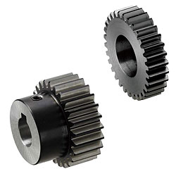
Straight gears / ductively hardened / contact angle 20 degrees

Part Number
Once your search is narrowed to one product,
the corresponding part number is displayed here.
- Drawing / Specifications
- 3D Preview 3D preview is available after complete configuration
- Part Numbers
- More Information
- Catalog
Back to the Category Spur Gears
Technical Drawing - Spur Gears
Open the technical drawing in the new window
Available dimensions and tolerances can be found under the tab More Information.
Basic Properties (e.g., material, hardness, coating, tolerance) - Spur Gears
| Type | Material | Surface Treatment | Hardness | Accessory | ||
| Straight Bore | Straight Bore + Tap | Keyway, Keyway + Tap | ||||
| GEAHBH | GEABH | GEAKBH | EN 1.1191 Equiv. | Black Oxide | Tooth Induction Hardened 51 ~ 55HRC (Depth 1mm or more) | Set Screw (EN 1.7220 Equiv. Black Oxide) |
Further specifications can be found under the tab More Information.
Composition of a Product Code - Spur Gears
| Part Number | - | Number of Teeth | - | B | - | Gear Shape | - | P |
| GEAKBH2.0 GEABH1.0 | - - | 30 30 | - - | 20 8 | - - | A B | - - | 25N 15 |
Alterations - Spur Gears
General Information - Spur Gears
Selection details of spur gears
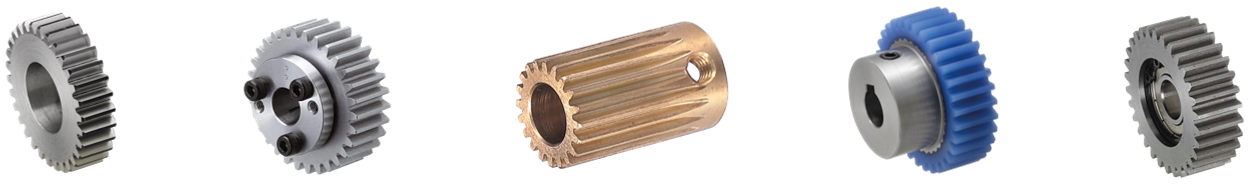
- Material: steel, stainless steel, sintered steel, nylon, polyacetal, brass, aluminum, cast iron
- Coatings: burnished, nickel-plated
- Heat treatment: induction hardened
- Shaft diameter tolerances: H7, H8
- Tooth flank clearance: N5, N7, N8, N9, N12
- Module: 0.3, 0.5, 0.75, 0.8, 1, 1.25, 1.5, 2, 2.5, 3, 4, 4.5, 5, 6, 8, 10, 15, 20
- Pressure angle: 20°
- Shaft diameter: 2 mm to 50 mm
- Number of teeth: 8 to 200
- Tooth width: 2 mm to 90 mm
Description/Basics
The spur gears offered are generally machine elements that serve the non-slip transmission of force, movement transmission or movement change. The teeth of the cylinder wheels grip each other during transmission and largely roll over the tooth flanks. The tooth shape of the spur gear is convexly shaped in the shaped tooth system. At the beginning of the intervention, a rolling resistance acts on the tooth flank, which becomes a sliding friction in the course of the rotation.
A combination of gear wheels and rack gears is useful in the construction of rack gear. This allows motor rotary motion or other rotary motion to be converted into linear motion. rack gear boxes are theoretically possible in an endless assembly. Limits here only set the length of the rack gears for the rack gear drive.
Gear wheels with straight gearing are particularly suitable for the construction of gearboxes. The advantage of straight gearing as opposed to helical gears, is the possibility of transmitting a higher torque. It should be noted that with increasing speed within the transmission ratio or reduction, the torque to be transmitted decreases.
When designing spur gear pairs, the ratio of the gear ratio (number of teeth) and the module of the respective gear wheels must be observed.
The backlash is another important factor that must be considered during construction. Reverse play is understood as the result of the play that the change in the direction of rotation of a single gear wheel pair between the teeth. The risk of reverse play can be reduced if either the diameter or the number of teeth of the cogwheel pairing do not deviate too much from one another. If high wear is to be expected due to the pairing of gears, the MISUMI online shop offers gears with a hardened key-type.
For applications with the same rotational direction, it is possible to use an intermediate gear with integrated bearing on a cantilever shaft. The bearing number used can be found under the tab More Information. An overview of tolerances and permissible radial bearing deviations can be found in the following PDF.
In addition to gear wheels, MISUMI also offers suitable rotary shafts for the construction of a transmission. The straight front wheels can be assembled on these and secured with a set screw or machine keys (key with adjusting screw). This PDF provides an overview of the configurable mountings for the shaft rotation and keyway tolerances.
The continuous adjusting of a spur gear can be realized, among other things, by means of a clamping sleeve. The MISUMI online shop offers spur gears with clamping sleeve. Alternatively, we also offer individual keyless bushing that you can customize to your needs.
Application Examples - Spur Gears
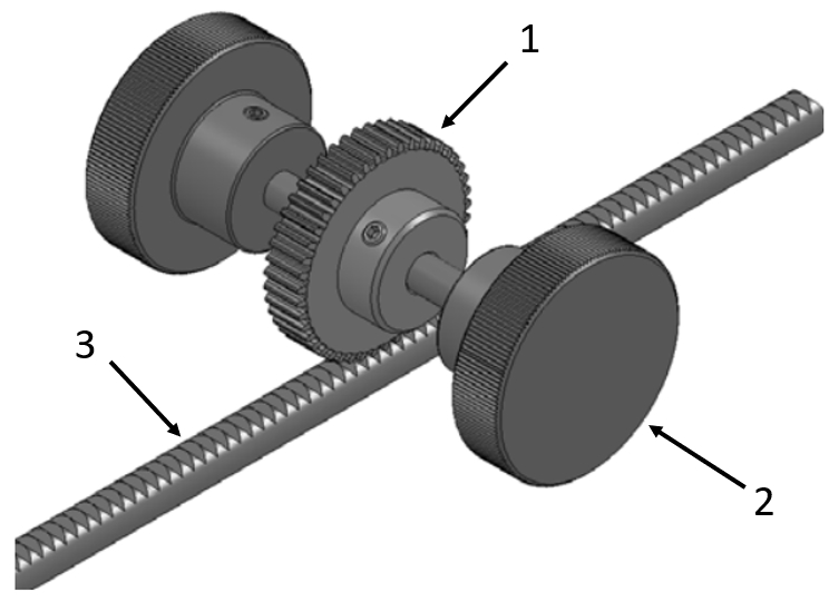
Application example - spur gear with rack gear
(1) Spur gear, (2) Clamping knobs, (3) Rack gear

Application example - spur gear
(1) Spur gear, (2) Workpiece, (3) Rollers
Industrial Applications


Part Number:
- In order to open the 3D preview, the part number must be fixed.
3D preview is not available, because the part number has not yet been determined.
| Part Number |
Standard Unit Price
| Minimum order quantity | Volume Discount | RoHS | Number of Teeth (Teeth) | Shape | Shaft Bore Dia. (Ø) | Tooth Width B (mm) | Hole Shape | |
|---|---|---|---|---|---|---|---|---|---|---|
- | 1 | 10 Days | 10 | 18 | Shape B | 6 ~ 10 | 8 | Round Hole + Tap | ||
- | 1 | 10 Days | 10 | 18 | Shape B | 6 ~ 10 | 8 | Round Hole + Tap | ||
- | 1 | 10 Days | 10 | 20 | Shape B | 6.35 | 8 | Round Hole + Tap | ||
- | 1 | 10 Days | 10 | 20 | Shape B | 6 ~ 11 | 8 | Round Hole + Tap | ||
- | 1 | 10 Days | 10 | 22 | Shape B | 8 ~ 14 | 8 | Round Hole + Tap | ||
- | 1 | 10 Days | 10 | 24 | Shape B | 8 ~ 14 | 8 | Round Hole + Tap | ||
- | 1 | 10 Days | 10 | 25 | Shape B | 8 ~ 14 | 8 | Round Hole + Tap | ||
- | 1 | 10 Days | 10 | 26 | Shape B | 8 ~ 14 | 8 | Round Hole + Tap | ||
- | 1 | 10 Days | 10 | 28 | Shape B | 8 ~ 14 | 8 | Round Hole + Tap | ||
- | 1 | 10 Days | 10 | 30 | Shape B | 10 ~ 17 | 8 | Round Hole + Tap | ||
- | 1 | 10 Days | 10 | 32 | Shape B | 10 ~ 17 | 8 | Round Hole + Tap | ||
- | 1 | 10 Days | 10 | 35 | Shape B | 10 ~ 17 | 8 | Round Hole + Tap | ||
- | 1 | 10 Days | 10 | 36 | Shape B | 10 ~ 17 | 8 | Round Hole + Tap | ||
- | 1 | 10 Days | 10 | 40 | Shape B | 10 ~ 21 | 8 | Round Hole + Tap | ||
- | 1 | 10 Days | 10 | 45 | Shape B | 10 ~ 21 | 8 | Round Hole + Tap | ||
- | 1 | 10 Days | 10 | 48 | Shape B | 10 ~ 21 | 8 | Round Hole + Tap | ||
- | 1 | 10 Days | 10 | 50 | Shape B | 12 ~ 24 | 8 | Round Hole + Tap | ||
- | 1 | 10 Days | 10 | 60 | Shape B | 12 ~ 28 | 8 | Round Hole + Tap | ||
- | 1 | 10 Days | 10 | 70 | Shape B | 12 ~ 28 | 8 | Round Hole + Tap | ||
- | 1 | 10 Days | 10 | 80 | Shape B | 15 ~ 35 | 8 | Round Hole + Tap | ||
- | 1 | 10 Days | 10 | 100 | Shape B | 15 ~ 35 | 8 | Round Hole + Tap | ||
- | 1 | 10 Days | 10 | 15 | Shape B | 10 ~ 12 | 15 | Round Hole + Tap | ||
- | 1 | 10 Days | 10 | 16 | Shape B | 10 ~ 13 | 15 | Round Hole + Tap | ||
- | 1 | 10 Days | 10 | 18 | Shape B | 10 ~ 15 | 15 | Round Hole + Tap | ||
- | 1 | 10 Days | 10 | 20 | Shape B | 10 ~ 16 | 15 | Round Hole + Tap | ||
- | 1 | 10 Days | 10 | 24 | Shape B | 12 ~ 19 | 15 | Round Hole + Tap | ||
- | 1 | 10 Days | 10 | 25 | Shape B | 12 ~ 21 | 15 | Round Hole + Tap | ||
- | 1 | 10 Days | 10 | 26 | Shape B | 12 ~ 22 | 15 | Round Hole + Tap | ||
- | 1 | 10 Days | 10 | 28 | Shape B | 15 ~ 25 | 15 | Round Hole + Tap | ||
- | 1 | 10 Days | 10 | 30 | Shape B | 15 ~ 26 | 15 | Round Hole + Tap | ||
- | 1 | 10 Days | 10 | 32 | Shape B | 15 ~ 28 | 15 | Round Hole + Tap | ||
- | 1 | 10 Days | 10 | 35 | Shape B | 15 ~ 29 | 15 | Round Hole + Tap | ||
- | 1 | 10 Days | 10 | 36 | Shape B | 15 ~ 31 | 15 | Round Hole + Tap | ||
- | 1 | 10 Days | 10 | 40 | Shape B | 15 ~ 35 | 15 | Round Hole + Tap | ||
- | 1 | 10 Days | 10 | 45 | Shape B | 18 ~ 35 | 15 | Round Hole + Tap | ||
- | 1 | 10 Days | 10 | 48 | Shape B | 18 ~ 35 | 15 | Round Hole + Tap | ||
- | 1 | 10 Days | 10 | 50 | Shape B | 18 ~ 42 | 15 | Round Hole + Tap | ||
- | 1 | 10 Days | 10 | 60 | Shape B | 20 ~ 42 | 15 | Round Hole + Tap | ||
- | 1 | 10 Days | 10 | 70 | Shape B | 20 ~ 42 | 15 | Round Hole + Tap | ||
- | 1 | 10 Days | 10 | 15 | Shape B | 12 ~ 17 | 20 | Round Hole + Tap | ||
- | 1 | 10 Days | 10 | 16 | Shape B | 12 ~ 18 | 20 | Round Hole + Tap | ||
- | 1 | 10 Days | 10 | 18 | Shape B | 12 ~ 21 | 20 | Round Hole + Tap | ||
- | 1 | 10 Days | 10 | 20 | Shape B | 15 ~ 22 | 20 | Round Hole + Tap | ||
- | 1 | 10 Days | 10 | 22 | Shape B | 15 ~ 22 | 20 | Round Hole + Tap | ||
- | 1 | 10 Days | 10 | 24 | Shape B | 15 ~ 26 | 20 | Round Hole + Tap | ||
- | 1 | 10 Days | 10 | 25 | Shape B | 15 ~ 28 | 20 | Round Hole + Tap | ||
- | 1 | 10 Days | 10 | 28 | Shape B | 15 ~ 31 | 20 | Round Hole + Tap | ||
- | 1 | 10 Days | 10 | 30 | Shape B | 18 ~ 35 | 20 | Round Hole + Tap | ||
- | 1 | 10 Days | 10 | 32 | Shape B | 18 ~ 35 | 20 | Round Hole + Tap | ||
- | 1 | 10 Days | 10 | 36 | Shape B | 18 ~ 35 | 20 | Round Hole + Tap | ||
- | 1 | 10 Days | 10 | 40 | Shape B | 20 ~ 42 | 20 | Round Hole + Tap | ||
- | 1 | 10 Days | 10 | 45 | Shape B | 20 ~ 42 | 20 | Round Hole + Tap | ||
- | 1 | 10 Days | 10 | 48 | Shape B | 20 ~ 42 | 20 | Round Hole + Tap | ||
- | 1 | 10 Days | 10 | 50 | Shape B | 25 ~ 42 | 20 | Round Hole + Tap | ||
- | 1 | 10 Days | 10 | 60 | Shape B | 25 ~ 45 | 20 | Round Hole + Tap | ||
- | 1 | 10 Days | 10 | 16 | Shape B | 15 ~ 22 | 25 | Round Hole + Tap | ||
- | 1 | 10 Days | 10 | 20 | Shape B | 18 ~ 28 | 25 | Round Hole + Tap | ||
- | 1 | 10 Days | 10 | 24 | Shape B | 18 ~ 33 | 25 | Round Hole + Tap | ||
- | 1 | 10 Days | 10 | 25 | Shape B | 20 ~ 35 | 25 | Round Hole + Tap | ||
- | 1 | 10 Days | 10 | 28 | Shape B | 20 ~ 42 | 25 | Round Hole + Tap |
Loading...
Back to the Category Spur Gears
Technical Drawing - Spur Gears
Open the technical drawing in the new window
Specification Tables - Spur Gears
| Part Number | Number of Teeth | B | Gear Shape | Shaft Hole Dia PH7 (1mm Increment) | d Reference Dia. | D Tip Dia. | G Root Dia. | H | L | ℓ1 | ℓ2 | *1. Allowable Transmission Force (N, m) Bending Strength | Unit Price 1 ~ 10 pc(s). | ||||
| Type | Module | Straight Bore Straight Bore + Tap | Keyway Keyway + Tap | ||||||||||||||
| Straight Bore | Straight Bore + Tap | Keyway Keyway + Tap | |||||||||||||||
| GEAHBH | GEABH | GEAKBH | |||||||||||||||
| Straight Bore (Shape A, Shape B) GEAHBH Straight Bore + Tap (Shape B) GEABH Keyway (Shape A) Keyway + Tap (Shape B) GEAKBH | 1.0 | 18 | 8 | A B | 6~10 | - | 18 | 20 | 15.5 | 15 | 18 | 10 | 5 | 4.76 | - | ||
| 20 | 6~11 | 8N, 10N | 20 | 22 | 17.5 | 17 | 5.57 | ||||||||||
| 22 | 8~14 | 8N~12N | 22 | 24 | 19.5 | 18 | 6.42 | ||||||||||
| 24 | 24 | 26 | 21.5 | 20 | 7.27 | ||||||||||||
| 25 | 25 | 27 | 22.5 | 7.69 | |||||||||||||
| 26 | 26 | 28 | 23.5 | 8.12 | |||||||||||||
| 28 | 28 | 30 | 25.5 | 9.02 | |||||||||||||
| 30 | 10~17 | 10N~15N | 30 | 32 | 27.5 | 25 | 9.87 | ||||||||||
| 32 | 32 | 34 | 29.5 | 10.79 | |||||||||||||
| 35 | 35 | 37 | 32.5 | 12.13 | |||||||||||||
| 36 | 36 | 38 | 33.5 | 12.52 | |||||||||||||
| 40 | 10~21 | 10N~18N | 40 | 42 | 37.5 | 30 | 13.07 | ||||||||||
| 45 | 45 | 47 | 42.5 | 15.18 | |||||||||||||
| 48 | 48 | 50 | 45.5 | 16.44 | |||||||||||||
| 50 | 12~24 | 12N~18N | 50 | 52 | 47.5 | 35 | 17.23 | ||||||||||
| 60 | 12~28 | 12N~25N | 60 | 62 | 57.5 | 40 | 21.50 | ||||||||||
| 70 | 70 | 72 | 67.5 | 25.74 | |||||||||||||
| 80 | 15~35 | 15N~30N | 80 | 82 | 77.5 | 50 | 29.98 | ||||||||||
| 100 | 100 | 102 | 97.5 | 38.72 | |||||||||||||
| 1.5 | 15 | 15 | 10~12 | 10N | 22.5 | 25.5 | 18.75 | 18 | 29 | 14 | 7 | 15.11 | |||||
| 16 | 10~13 | 10N, 11N | 24 | 27 | 20.25 | 19.5 | 16.74 | ||||||||||
| 18 | 10~15 | 10N~13N | 27 | 30 | 23.25 | 22 | 20.08 | ||||||||||
| 20 | 10~16 | 10N~14N | 30 | 33 | 26.25 | 24 | 23.51 | ||||||||||
| 24 | 12~19 | 12N~17N | 36 | 39 | 32.25 | 28 | 30.56 | ||||||||||
| 25 | 12~21 | 12N~18N | 37.5 | 40.5 | 33.75 | 30 | 32.39 | ||||||||||
| 26 | 12~22 | 12N~19N | 39 | 42 | 35.25 | 32 | 31.16 | ||||||||||
| 28 | 15~25 | 15N~19N | 42 | 45 | 38.25 | 36 | 34.58 | ||||||||||
| 30 | 15~26 | 15N~23N | 45 | 48 | 41.25 | 38 | 37.84 | ||||||||||
| 32 | 15~28 | 15N~24N | 48 | 51 | 44.25 | 40 | 41.03 | ||||||||||
| 35 | 15~29 | 15N~26N | 52.5 | 55.5 | 48.75 | 42 | 46.51 | ||||||||||
| 36 | 15~31 | 15N~28N | 54 | 57 | 50.25 | 45 | 48.00 | ||||||||||
| 40 | 15~35 | 15N~31N | 60 | 63 | 56.25 | 50 | 54.90 | ||||||||||
| 45 | 18~35 | 18N~31N | 67.5 | 70.5 | 63.75 | 63.90 | |||||||||||
| 48 | 72 | 75 | 68.25 | 69.20 | |||||||||||||
| 50 | 18~42 | 18N~38N | 75 | 78 | 71.25 | 60 | 72.69 | ||||||||||
| 60 | 20~42 | 20N~38N | 90 | 93 | 86.25 | 90.68 | |||||||||||
| 70 | 105 | 108 | 101.25 | 108.59 | |||||||||||||
Specify 10K as P dimension if keyway width of 4.0mm (height 1.8mm) for Keyway + Tap with shaft bore diameter of 10 is desired. >> P.1498
*1 Allowable Transmission Forces in the table are reference values calculated with prescribed conditions. For conditions, see >> P. 1498.
For orders larger than indicated quantity, please request a quotation.
■Module 2.0, 2.5, 3.0
| Part Number | Number of Teeth | B | Gear Shape | Shaft Hole Dia PH7 (1mm Increment) | d Reference Dia. | D Tip Dia. | G Root Dia. | H | L | ℓ1 | ℓ2 | *1. Allowable Transmission Force (N • m) Bending Strength | Unit Price 1 ~ 30 pc(s). | ||||
| Type | Module | Straight Bore Straight Bore + Tap | Keyway Keyway + Tap | ||||||||||||||
| Straight Bore | Straight Bore + Tap | Keyway Keyway + Tap | |||||||||||||||
| GEAHBH | GEABH | GEAKBH | |||||||||||||||
| Straight Bore (Shape A, Shape B) GEAHBH Straight Bore + Tap (Shape B) GEABH Keyway (Shape A) Keyway + Tap (Shape B) GEAKBH | 2.0 | 15 | 20 | A B | 12~17 | 12N~14N | 30 | 34 | 25 | 24 | 36 | 16 | 8 | 35.81 | |||
| 16 | 12~18 | 12N~15N | 32 | 36 | 27 | 26 | 39.67 | ||||||||||
| 18 | 12~21 | 12N~18N | 36 | 40 | 31 | 30 | 47.59 | ||||||||||
| 20 | 15~22 | 15N~19N | 40 | 44 | 35 | 32 | 50.67 | ||||||||||
| 22 | 44 | 48 | 39 | 36 | 58.24 | ||||||||||||
| 24 | 15~26 | 15N~23N | 48 | 52 | 43 | 38 | 65.86 | ||||||||||
| 25 | 15~28 | 15N~24N | 50 | 54 | 45 | 40 | 69.81 | ||||||||||
| 28 | 15~31 | 15N~28N | 56 | 60 | 51 | 45 | 81.96 | ||||||||||
| 30 | 18~35 | 18N~31N | 60 | 64 | 55 | 50 | 89.70 | ||||||||||
| 32 | 64 | 68 | 59 | 97.27 | |||||||||||||
| 36 | 72 | 76 | 67 | 113.78 | |||||||||||||
| 40 | 20~42 | 20N~38N | 80 | 84 | 75 | 60 | 130.13 | ||||||||||
| 45 | 90 | 94 | 85 | 151.46 | |||||||||||||
| 48 | 96 | 100 | 91 | 164.04 | |||||||||||||
| 50 | 25~42 | 25N~38N | 100 | 104 | 95 | 172.31 | |||||||||||
| 60 | 25~45 | 25N~42N | 120 | 124 | 115 | 65 | 205.60 | ||||||||||
| 2.5 | 16 | 25 | 15~22 | 15N~19N | 40 | 45 | 33.75 | 32 | 43 | 18 | 9 | 70.43 | |||||
| 20 | 18~28 | 18N~24N | 50 | 55 | 43.75 | 40 | 98.97 | ||||||||||
| 24 | 18~33 | 18N~30N | 60 | 65 | 53.75 | 48 | 128.63 | ||||||||||
| 25 | 20~35 | 20N~31N | 62.5 | 67.5 | 56.25 | 50 | 136.34 | ||||||||||
| 28 | 20~42 | 20N~38N | 70 | 75 | 63.75 | 60 | 160.07 | ||||||||||
| 30 | 20~45 | 20N~42N | 75 | 80 | 68.75 | 65 | 175.19 | ||||||||||
| 36 | 20~49 | 20N~45N | 90 | 95 | 83.75 | 70 | 222.23 | ||||||||||
| 40 | 25~49 | 25N~45N | 100 | 105 | 93.75 | 254.16 | |||||||||||
| 45 | 25~52 | 25N~49N | 112.5 | 117.5 | 106.25 | 75 | 295.82 | ||||||||||
| 48 | 120 | 125 | 113.75 | 306.46 | |||||||||||||
| 50 | 25~56 | 25N~50N | 125 | 130 | 118.75 | 80 | 321.92 | ||||||||||
| 3.0 | 16 | 30 | 16~26 | 16N~23N | 48 | 54 | 40.5 | 38 | 50 | 20 | 10 | 121.71 | |||||
| 20 | 20~35 | 20N~31N | 60 | 66 | 52.5 | 50 | 171.01 | ||||||||||
| 24 | 20~40 | 20N~37N | 72 | 78 | 64.5 | 58 | 222.27 | ||||||||||
| 25 | 20~42 | 20N~38N | 75 | 81 | 67.5 | 60 | 235.60 | ||||||||||
| 30 | 25~52 | 25N~49N | 90 | 96 | 82.5 | 75 | 302.72 | ||||||||||
| 32 | 96 | 102 | 88.5 | 328.27 | |||||||||||||
| 36 | 25~56 | 25N~50N | 108 | 114 | 100.5 | 80 | 384.01 | ||||||||||
| 40 | 120 | 126 | 112.5 | 420.10 | |||||||||||||
For orders larger than indicated quantity, please request a quotation.
| 8~17 | 36 | 38 | 33.5 | 5 | M5 | 7.51 | 4.29 | |||||||||||||
| *38 | 38 | 40 | 35.5 | 8.08 | - | - | - | - | ||||||||||||
| 40 | 40 | 42 | 37.5 | 28 | 8.59 | 4.90 | ||||||||||||||
| 42 | 42 | 44 | 39.5 | 9.14 | 5.22 | |||||||||||||||
| *44 | 44 | 46 | 41.5 | 9.71 | - | - | - | - | ||||||||||||
| *45 | 45 | 47 | 42.5 | 10.00 | - | - | - | - | ||||||||||||
| *46 | 8~20 | 8N~17N | 46 | 48 | 43.5 | 30 | 10.29 | - | - | - | - | |||||||||
| 48 | 8~25 | 8N~24N | 48 | 50 | 45.5 | 40 | 10.83 | 6.18 | ||||||||||||
| 50 | 50 | 52 | 47.5 | 11.37 | 6.49 | |||||||||||||||
| *52 | 10N~24N | 52 | 54 | 49.5 | 11.92 | - | - | - | - | |||||||||||
| 54 | 54 | 56 | 51.5 | 12.48 | 7.12 | |||||||||||||||
| 55 | 55 | 57 | 52.5 | 12.79 | 7.30 | |||||||||||||||
| 56 | 56 | 58 | 53.5 | 13.10 | 7.48 | |||||||||||||||
| 58 | 58 | 60 | 55.5 | 13.61 | 7.77 | |||||||||||||||
| 60 | 8~30 | 10N~27N | 60 | 62 | 57.5 | 44 | 14.19 | 8.10 | ||||||||||||
| 62 | 10~30 | 12N~27N | 62 | 64 | 59.5 | 14.70 | 8.39 | |||||||||||||
| 64 | 64 | 66 | 61.5 | 15.28 | 8.72 | |||||||||||||||
| 65 | 65 | 67 | 62.5 | 15.54 | 8.87 | |||||||||||||||
| 66 | 66 | 68 | 63.5 | 15.87 | 9.06 | |||||||||||||||
| 68 | 68 | 70 | 65.5 | 16.47 | 9.40 | |||||||||||||||
| 70 | 10~35 | 12N~30N | 70 | 72 | 67.5 | 48 | 16.99 | 9.69 | ||||||||||||
| 72 | 72 | 74 | 69.5 | 17.51 | 9.99 | |||||||||||||||
| 75 | 75 | 77 | 72.5 | 18.38 | 10.49 | |||||||||||||||
| 80 | 10~35 | 12N~31N | 80 | 82 | 77.5 | 50 | 19.79 | 11.29 | ||||||||||||
| 84 | 15~35 | 15N~31N | 84 | 86 | 81.5 | 20.94 | 11.95 | |||||||||||||
| 85 | 85 | 87 | 82.5 | 21.21 | 12.10 | |||||||||||||||
| 90 | 90 | 92 | 87.5 | 22.64 | 12.92 | |||||||||||||||
| 95 | 95 | 97 | 92.5 | 24.09 | 13.75 | |||||||||||||||
| 96 | 96 | 98 | 93.5 | 24.36 | 13.90 | |||||||||||||||
| 100 | 100 | 102 | 97.5 | 25.56 | 14.58 | |||||||||||||||
| 110 | 110 | 112 | 107.5 | 28.27 | 16.13 | |||||||||||||||
| 120 | 15N~34N | 120 | 122 | 117.5 | 54 | 31.12 | 17.76 |
Shaft bore diameter 9N is not available for Keyway Bore + Tap.
Specify 10K as the P dimension if keyway width of 4.0mm (height 1.8mm) for Keyway + Tap with shaft bore diameter of 10 is desired. >> P.1498
Shaft bore diameter 6.35 is available for Straight Bore and Straight Bore + Tap.
*1 Allowable Transmission Forces in the table are reference values calculated with prescribed conditions. For conditions, see >> P. 1498.
Tooth width is calculated as 6mm.
Alterations - Spur Gears
Basic information
| Material (Details) | General Steel Material | Heat Treatment (Details) | Induction Hardened | Surface Treatment | Black Oxide |
|---|---|---|---|---|---|
| Ground Tooth | Provided | Backlash | Provided | Bearing | Not Provided |
| Shaft Bore Tolerance | H7 | Precision(Old JIS) | JIS B 1702 (Class 2) |
Configure
Basic Attributes
-
Number of Teeth(Teeth)
-
Shape
-
 Shape A
 -
 Shape B
-
-
Shaft Bore Dia.(Ø)
- 6
- 6.35
- 7
- 8
- 9
- 10
- 11
- 12
- 13
- 14
- 15
- 16
- 17
- 18
- 19
- 20
- 21
- 22
- 23
- 24
- 25
- 26
- 27
- 28
- 29
- 30
- 31
- 32
- 33
- 34
- 35
- 36
- 37
- 38
- 39
- 40
- 41
- 42
- 43
- 44
- 45
- 46
- 47
- 48
- 49
- 50
[6-56/1Ø Unit(s)]
-
Tooth Width B(mm)
-
Hole Shape
- Keyway
- Keyway Hole + Tap
- Round Hole
- Round Hole + Tap
-
Type
- GEABH
- GEAHBH
- GEAKBH
-
Filter by CAD data type
- 2D
- 3D


Filter by standard shipping days
-
- All
- 10 Days or Less
Optional Attributes
- The specifications and dimensions of some parts may not be fully covered. For exact details, refer to manufacturer catalogs .
Frequently Asked Questions (FAQ)
-
Question:
Can different modules be combined with each other?
-
Answer:
Since the module describes the division of the teeth along the pitch circle diameter, various modules cannot be combined into one pair of gears.
-
Question:
What is involute gearing?
-
Answer:
Evolved gearing is understood to be the convex production of a tooth flank. The sliding friction along the tooth flank can thus be minimized. This also reduces wear and tear.
-
Question:
What is the pressure angle?
-
Answer:
The pressure angle is defined as the angle of the highest drive force between two gears. A combination of different pressure angles is not recommended, since increased wear is to be expected.
-
Question:
Is the position of the keyway to the key-type specified?
-
Answer:
The keyway has no specified position reference to the tooth base or the head surface of the sprocket.
-
Question:
What is the reverse clearance?
-
Answer:
The reverse play arises at the moment of the direction of rotation of a spur gear pairing is changed. It describes the gap between the gear flanks of each tooth in engagement.
Complementary Products
-
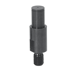 Cantilever Shafts / shouldered / external thread, ring groove / spanner flat
MISUMI Shipping Days: 3 Days
-
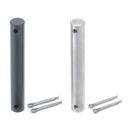 Hinge pins / stainless steel, steel / two-sided split pin hole / incl. split pin
MISUMI Shipping Days: Same day
-
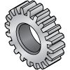
 Rack gears / contact angle 20 degrees / dimension L standard
MISUMI Standard Price : 7.34 € Shipping Days: Same day


MISUMI Unit еxample related to this product


Tech Support
- Technical Support
- Tel:+49 69 668173-0 / FAX:+49 69 668173-360
- Technical Inquiry
Payment Method


On-Demand Manufacturing
Certificates


Copyright © MISUMI Corporation All Rights Reserved.