Round Wire Coil Springs / Deflection 27%-30% / O.D. Referenced (Part Numbers - CAD Download)

- Promotional pricing
- Volume Discount
- Order quantities extended (D-JIT)
- Stock
(i)Remark
- Please check the content on our website as the PDF does not contain the most up-to-date information.
Part Number
Once your search is narrowed to one product,
the corresponding part number is displayed here.
- Drawing / Specifications
- 3D Preview 3D preview is available after complete configuration
- Part Numbers
- Catalog
- Technical Information
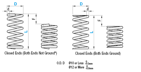
Material EN 1.4301 (WPB) Equiv. Spring Constant ±10%
Specifications
| Part Number |
| UM16-80 UH16-80 |
| Part Number | d | Solid Length | F max. | N{kgf}max. | Fa% | Unit Price | ||
| TypeD-L | ||||||||
| UM 4- | 5* | 0.4 | 2.2 | 1.75 | 3.4 | {0.35} | 35 | |
| 10* | 0.5 | 4.9 | 3.5 | 6.8 | {0.7 } | |||
| 15 | 0.55 | 7.5 | 5.25 | 10.3 | {1.05} | |||
| 20 | 0.6 | 11.1 | 7 | 13.7 | {1.4 } | |||
| 25 | 0.6 | 11.1 | 8.75 | 17.2 | {1.75} | |||
| 30 | 0.65 | 16.3 | 10.5 | 20.6 | {2.1 } | |||
| UM 5- | 5* | 0.45 | 2.25 | 1.75 | 3.4 | {0.35} | 35 | |
| 10* | 0.5 | 3.13 | 3.5 | 6.8 | {0.7 } | |||
| 15 | 0.65 | 8.45 | 5.25 | 10.3 | {1.05} | |||
| 20 | 0.65 | 8.45 | 7 | 13.7 | {1.4 } | |||
| 25 | 0.7 | 11.9 | 8.75 | 17.2 | {1.75} | |||
| 30 | 0.7 | 11.9 | 10.5 | 20.6 | {2.1 } | |||
| 35 | 0.75 | 16.5 | 12.25 | 24.0 | {2.45} | |||
| 40 | 0.8 | 23.2 | 14 | 27.5 | {2.8 } | |||
| 45 | 0.8 | 23.2 | 15.75 | 30.9 | {3.15} | |||
| 50 | 0.85 | 31.45 | 17.5 | 34.3 | {3.5 } | |||
| UM 6- | 5* | 0.55 | 2.7 | 1.7 | 4.9 | {0.5 } | 35 | |
| 10 | 0.7 | 5.6 | 3.5 | 10.8 | {1.1 } | |||
| 15 | 0.75 | 7.4 | 5.2 | 15.7 | {1.6 } | |||
| 20 | 0.75 | 7.4 | 7 | 20.6 | {2.1 } | |||
| 25 | 0.85 | 12.8 | 8.7 | 25.5 | {2.6 } | |||
| 30 | 0.85 | 12.8 | 10.5 | 31.4 | {3.2 } | |||
| 35 | 0.9 | 16.7 | 12.2 | 36.3 | {3.7 } | |||
| 40 | 0.9 | 16.8 | 14 | 41.2 | {4.2 } | |||
| 45 | 1.0 | 27.8 | 15.75 | 46.1 | {4.7 } | |||
| 50 | 1.0 | 28.0 | 17.5 | 52.0 | {5.3 } | |||
| 60 | 1.0 | 28.0 | 18 | 53.0 | {5.4 } | 30 | ||
| 70 | 1.1 | 46.2 | 19.6 | 58.8 | {6 } | 28 | ||
| UM 8- | 10 | 0.85 | 6.4 | 3.5 | 10.8 | {1.1 } | 35 | |
| 15 | 0.9 | 7.9 | 5.2 | 15.7 | {1.6 } | |||
| 20 | 0.9 | 7.9 | 7 | 20.6 | {2.1 } | |||
| 25 | 0.9 | 7.9 | 8.7 | 25.5 | {2.6 } | |||
| 30 | 1.0 | 12.0 | 10.5 | 31.4 | {3.2 } | |||
| 35 | 1.0 | 12.0 | 12.2 | 36.3 | {3.7 } | |||
| 40 | 1.1 | 18.7 | 14 | 41.2 | {4.2 } | |||
| 45 | 1.1 | 18.7 | 15.75 | 46.1 | {4.7 } | |||
| 50 | 1.1 | 18.7 | 17.5 | 52.0 | {5.3 } | |||
| 60 | 1.2 | 28.2 | 21 | 61.8 | {6.3 } | |||
| 70 | 1.3 | 42.0 | 24.5 | 72.6 | {7.4 } | |||
| UM10- | 10 | 0.9 | 5.2 | 3.5 | 10.8 | {1.1} | 35 | |
| 15 | 1.0 | 7.3 | 5.2 | 15.7 | {1.6} | |||
| 20 | 1.0 | 7.3 | 7 | 20.6 | {2.1} | |||
| 25 | 1.1 | 10.5 | 8.7 | 25.5 | {2.6} | |||
| 30 | 1.1 | 10.5 | 10.5 | 31.4 | {3.2} | |||
| 35 | 1.2 | 15 | 12.2 | 36.3 | {3.7} | |||
| 40 | 1.2 | 15 | 14 | 41.2 | {4.2} | |||
| 45 | 1.3 | 21.8 | 15.75 | 46.1 | {4.7} | |||
| 50 | 1.3 | 21.8 | 17.5 | 52.0 | {5.3} | |||
| 60 | 1.4 | 30.8 | 21 | 61.8 | {6.3} | |||
| 70 | 1.4 | 30.8 | 24.5 | 72.6 | {7.4} | |||
| UM13- | 15 | 1.2 | 8.4 | 5.2 | 15.7 | {1.6} | 35 | |
| 20 | 1.3 | 11.1 | 7 | 20.6 | {2.1} | |||
| 25 | 1.3 | 11.1 | 8.7 | 25.5 | {2.6} | |||
| 30 | 1.4 | 15.1 | 10.5 | 31.4 | {3.2} | |||
| 35 | 1.4 | 15.1 | 12.2 | 36.3 | {3.7} | |||
| 40 | 1.4 | 15.1 | 14 | 41.2 | {4.2} | |||
| 45 | 1.4 | 15.1 | 15.75 | 46.1 | {4.7} | |||
| 50 | 1.4 | 15.1 | 17.5 | 52.0 | {5.3} | |||
| 60 | 1.6 | 27.2 | 21 | 61.8 | {6.3} | |||
| 70 | 1.6 | 27.2 | 24.5 | 72.6 | {7.4} | |||
| 80 | 1.7 | 36.2 | 28 | 82.4 | {8.4} | |||
| UM16- | 15 | 1.4 | 9.6 | 5.2 | 15.7 | { 1.6} | 35 | |
| 20 | 1.5 | 12.4 | 7 | 20.6 | { 2.1} | |||
| 25 | 1.5 | 12.4 | 8.7 | 25.5 | { 2.6} | |||
| 30 | 1.5 | 12.4 | 10.5 | 31.4 | { 3.2} | |||
| 35 | 1.6 | 15.6 | 12.2 | 36.3 | { 3.7} | |||
| 40 | 1.6 | 15.6 | 14 | 41.2 | { 4.2} | |||
| 45 | 1.7 | 20.4 | 15.75 | 46.1 | { 4.7} | |||
| 50 | 1.7 | 20.4 | 17.5 | 52.0 | { 5.3} | |||
| 60 | 1.8 | 26.1 | 21 | 61.8 | { 6.3} | |||
| 70 | 1.8 | 26.1 | 24.5 | 72.6 | { 7.4} | |||
| 80 | 1.8 | 26.1 | 28 | 82.4 | { 8.4} | |||
| UM20- | 20 | 1.8 | 11.3 | 7 | 34.3 | { 3.5} | 35 | |
| 25 | 1.9 | 13.3 | 8.75 | 43.1 | { 4.4} | |||
| 30 | 1.9 | 13.3 | 10.5 | 52.0 | { 5.3} | |||
| 35 | 2 | 16 | 12.25 | 59.8 | { 6.1} | |||
| 40 | 2 | 16 | 14 | 68.6 | { 7 } | |||
| 45 | 2.2 | 23.7 | 15.75 | 77.5 | { 7.9} | |||
| 50 | 2.2 | 23.7 | 17.5 | 86.3 | { 8.8} | |||
| 60 | 2.2 | 23.7 | 21 | 103.0 | {10.5} | |||
| 70 | 2.4 | 34.8 | 24.5 | 120.6 | {12.3} | |||
| 80 | 2.4 | 34.8 | 28 | 137.3 | {14 } | |||
{kgf}=Nx0.101972
For Types marked with *, both ends are not ground.
The values of solid length are for reference only.
There may be some variations depending on the lot.
Usage Count: 1 Million Times
■UH: Fmax. (Allowable Deflection)=LxFa%
| Part Number | d | Solid Length | F max. | N{kgf}max. | Fa% | Unit Price | ||
| Type D-L | ||||||||
| UH 4- | 5* | 0.45 | 2.7 | 1.5 | 4.4 | { 0.45} | 30 | |
| 10* | 0.5 | 3.8 | 3 | 8.8 | { 0.9 } | |||
| 15 | 0.6 | 8.1 | 4.5 | 13.2 | { 1.35} | |||
| 20 | 0.65 | 11.7 | 6 | 17.6 | { 1.8 } | |||
| 25 | 0.7 | 16.8 | 7.5 | 22.1 | { 2.25} | |||
| 30 | 0.7 | 16.8 | 9 | 26.5 | { 2.7 } | |||
| UH 5- | 5* | 0.55 | 3.3 | 1.5 | 4.4 | { 0.45} | 30 | |
| 10 | 0.6 | 4.65 | 3 | 8.8 | { 0.9 } | |||
| 15 | 0.6 | 4.65 | 4.5 | 13.2 | { 1.35} | |||
| 20 | 0.75 | 11.81 | 6 | 17.6 | { 1.8 } | |||
| 25 | 0.75 | 11.81 | 7.5 | 22.1 | { 2.25} | |||
| 30 | 0.8 | 16 | 9 | 26.5 | { 2.7 } | |||
| 35 | 0.85 | 21.68 | 10.5 | 30.9 | { 3.15} | |||
| 40 | 0.85 | 21.68 | 12 | 35.3 | { 3.6 } | |||
| 45 | 0.9 | 28.8 | 13.5 | 39.7 | { 4.05} | |||
| UH 6- | 5* | 0.65 | 3.2 | 1.5 | 8.8 | { 0.9 } | 30 | |
| 10 | 0.7 | 3.9 | 3 | 17.7 | { 1.8 } | |||
| 15 | 0.85 | 7.7 | 4.5 | 26.5 | { 2.7 } | |||
| 20 | 0.9 | 9.7 | 6 | 35.3 | { 3.6 } | |||
| 25 | 1.0 | 15.5 | 7.5 | 44.1 | { 4.5 } | |||
| 30 | 1.0 | 15.5 | 9 | 53.0 | { 5.4 } | |||
| 35 | 1.1 | 24.8 | 9.8 | 57.9 | { 5.9 } | 28 | ||
| 40 | 1.1 | 24.8 | 10 | 58.8 | { 6 } | 25 | ||
| 45 | 1.1 | 24.8 | 11.25 | 66.7 | { 6.8 } | |||
| 50 | 1.2 | 39.0 | 10 | 58.8 | { 6 } | 20 | ||
| 60 | 1.2 | 39.0 | 13.8 | 82.4 | { 8.4 } | 23 | ||
| 70 | 1.2 | 39.0 | 14.7 | 88.3 | { 9 } | 21 | ||
| UH 8- | 10 | 0.9 | 5.3 | 3 | 17.7 | { 1.8 } | 30 | |
| 15 | 0.9 | 5.3 | 4.5 | 26.5 | { 2.7 } | |||
| 20 | 1.1 | 11 | 6 | 35.3 | { 3.6 } | |||
| 25 | 1.1 | 11 | 7.5 | 44.1 | { 4.5 } | |||
| 30 | 1.2 | 15.9 | 9 | 53.0 | { 5.4 } | |||
| 35 | 1.2 | 15.9 | 10.5 | 61.8 | { 6.3 } | |||
| 40 | 1.3 | 23.1 | 12 | 70.6 | { 7.2 } | |||
| 45 | 1.3 | 23.1 | 13.5 | 79.4 | { 8.1 } | |||
| 50 | 1.4 | 33.3 | 15 | 88.3 | { 9 } | |||
| 60 | 1.4 | 33.3 | 18 | 105.9 | {10.8 } | |||
| 70 | 1.5 | 48.0 | 18.9 | 111.8 | {11.4 } | 27 | ||
| UH 10- | 10 | 1.1 | 6.9 | 3 | 17.7 | { 1.8} | 30 | |
| 15 | 1.1 | 6.9 | 4.5 | 26.5 | { 2.7} | |||
| 20 | 1.2 | 9.3 | 6 | 35.3 | { 3.6} | |||
| 25 | 1.2 | 9.3 | 7.5 | 44.1 | { 4.5} | |||
| 30 | 1.3 | 12.7 | 9 | 53.0 | { 5.4} | |||
| 35 | 1.4 | 17.5 | 10.5 | 61.8 | { 6.3} | |||
| 40 | 1.4 | 17.5 | 12 | 70.6 | { 7.2} | |||
| 45 | 1.5 | 23.8 | 13.5 | 79.4 | { 8.1} | |||
| 50 | 1.5 | 23.8 | 15 | 88.3 | { 9 } | |||
| 60 | 1.6 | 32.4 | 18 | 105.9 | {10.8} | |||
| 70 | 1.7 | 44.2 | 21 | 123.6 | {12.6} | |||
| UH 13- | 15 | 1.5 | 9.2 | 4.5 | 44.1 | { 4.5} | 30 | |
| 20 | 1.5 | 9.2 | 6 | 58.8 | { 6 } | |||
| 25 | 1.5 | 9.2 | 7.5 | 73.5 | { 7.5} | |||
| 30 | 1.8 | 18 | 9 | 88.3 | { 9 } | |||
| 35 | 1.8 | 18 | 10.5 | 103.0 | {10.5} | |||
| 40 | 1.8 | 18 | 12 | 117.7 | {12 } | |||
| 45 | 1.8 | 18 | 13.5 | 132.4 | {13.5} | |||
| 50 | 2.0 | 28.5 | 15 | 147.0 | {15 } | |||
| 60 | 2.1 | 36 | 18 | 176.5 | {18 } | |||
| 70 | 2.2 | 45.1 | 21 | 205.9 | {21 } | |||
| 80 | 2.2 | 45.1 | 20 | 196.1 | {20 } | 25 | ||
| UH 16- | 15 | 1.7 | 9.6 | 4.5 | 44.1 | { 4.5} | 30 | |
| 20 | 1.9 | 14 | 6 | 58.8 | { 6 } | |||
| 25 | 1.9 | 14 | 7.5 | 73.5 | { 7.5} | |||
| 30 | 1.9 | 14 | 9 | 88.3 | { 9 } | |||
| 35 | 1.9 | 14 | 10.5 | 103.0 | {10.5} | |||
| 40 | 2.2 | 25.1 | 12 | 117.7 | {12 } | |||
| 45 | 2.2 | 25.1 | 13.5 | 132.4 | {13.5} | |||
| 50 | 2.2 | 25.1 | 15 | 147.1 | {15 } | |||
| 60 | 2.3 | 30.5 | 18 | 176.5 | {18 } | |||
| 70 | 2.5 | 44.7 | 21 | 205.9 | {21 } | |||
| 80 | 2.5 | 44.7 | 24 | 235.4 | {24 } | |||
| UH 20- | 25 | 2.3 | 13.8 | 7.5 | 110.8 | {11.3} | 30 | |
| 30 | 2.3 | 13.8 | 9 | 132.4 | {13.5} | |||
| 35 | 2.5 | 18.8 | 10.5 | 154.9 | {15.8} | |||
| 40 | 2.5 | 18.8 | 12 | 176.5 | {18 } | |||
| 45 | 2.8 | 29.4 | 13.5 | 199.1 | {20.3} | |||
| 50 | 2.8 | 29.4 | 15 | 220.6 | {22.5} | |||
| 60 | 3 | 40.5 | 18 | 264.8 | {27 } | |||
| 70 | 3 | 40.5 | 21 | 308.9 | {31.5} | |||
| 80 | 3.2 | 54.4 | 24 | 353.0 | { 36 } | |||
{kgf}=Nx0.101972
For Types marked with *, both ends are not ground.
The values of solid length are for reference only.
There may be some variations depending on the lot.
Usage Count: 1 Million Times
■Spring Constant
D12 is applicable to UY, UR, UF, UL and UBB Types only. D14 is applicable to UBB Type only.
| Type | UV | UY | UR | UF | UL | UTT | UM | UH | UBB | |||||||||||||||||||
| D | ||||||||||||||||||||||||||||
| 2 | 0.05{0.005} | 0.2{0.02} | 0.3{0.03} | 0.5{0.05} | ||||||||||||||||||||||||
| 3 | N/mm 0.05 {kgf/mm} {0.005} | N/mm 0.098 {kgf/mm} {0.01} | N/mm 0.29 {kgf/mm} {0.03} | N/mm 0.49 {kgf/mm} {0.05} | N/mm 0.98 {kgf/mm} {0.1} | N/mm 1.5 {kgf/mm} {0.15} | ||||||||||||||||||||||
| 4 | 2.0{0.2} | 2.9{0.3} | 4.9{0.5} | |||||||||||||||||||||||||
| 5 | ||||||||||||||||||||||||||||
| 6 | N/mm 2.0 {kgf/mm} {0.2} | N/mm 2.9 {kgf/mm} {0.3} | N/mm 5.9 {kgf/mm} {0.6} | N/mm 9.8 {kgf/mm} {1.0} | ||||||||||||||||||||||||
| 8 | ||||||||||||||||||||||||||||
| 10 | N/mm 0.2 {kgf/mm} {0.02} | |||||||||||||||||||||||||||
| 12 | ||||||||||||||||||||||||||||
| 13 | N/mm 9.8 {kgf/mm} {1.0} | N/mm 19.6 {kgf/mm} {2.0} | ||||||||||||||||||||||||||
| 14 | ||||||||||||||||||||||||||||
| 16 | ||||||||||||||||||||||||||||
| 20 | 0.3{0.03} | 0.5{0.05} | 0.98{0.1} | 2.9{0.3} | 3.9{0.4} | 4.9{0.5} | 14.7{1.5} | 29.4{3.0} | ||||||||||||||||||||
| Fmax. | F=Lx70% | F=LxFa% | F=LxFa% | F=Lx45% | F=Lx40% | F=LxFa% | F=LxFa% | F=LxFa% | F=L×Fa% | |||||||||||||||||||
Alterations
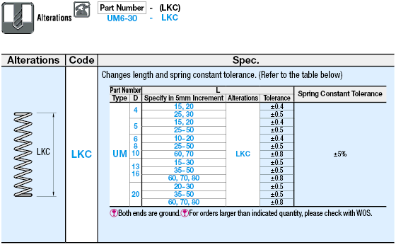

Part Number:
- In order to open the 3D preview, the part number must be fixed.
3D preview is not available, because the part number has not yet been determined.
Part Number
|
|---|
| UM20-40 |
| UM20-40-LKC |
| Part Number |
Standard Unit Price
| Minimum order quantity | Volume Discount | RoHS | Allowable Load (Configurable Range) (N) | End Surface Status | Max. Load (N) | Height upon Max. Load applied L-F (mm) | Free Length L (mm) | Outer Dia. D (or D1) (mm) | Spring Constant (N/mm) | Wire Dia. (mm) | Solid Length (mm) | Tolerance Change | Allowable Deflection (mm) | |
|---|---|---|---|---|---|---|---|---|---|---|---|---|---|---|---|---|
3.53 € | 1 | Available | 5 Days | 10 | 50.01 to 73.00 | With Grinding | 68.6 | 26 | 40 | 20 | 4.9 | 2 | 16 | - | 14 | |
6.66 € | 1 | Available | 9 Days | 10 | 50.01 to 73.00 | With Grinding | 68.6 | 26 | 40 | 20 | 4.9 | 2 | 16 | LKC (with Tolerance Change) | 14 |
Loading...
Basic information
| Material | EN 1.4301 (WPB) Equiv. |
|---|
Configure
Stock
-
- Show only stock items
Basic Attributes
-
End Surface Status
- With Grinding
- Without Grinding
-
Max. Load(N)
- 3.4
- 4.4
- 4.9
- 6.8
- 8.8
- 10.3
- 10.8
- 13.2
- 13.7
- 15.7
- 17.2
- 17.6
- 17.7
- 20.6
- 22.1
- 24
- 25.5
- 26.5
- 27.5
- 30.9
- 31.4
- 34.3
- 35.3
- 36.3
- 39.7
- 41.2
- 43.1
- 44.1
- 46.1
- 52
- 53
- 57.9
- 58.8
- 59.8
- 61.8
- 66.7
- 68.6
- 70.6
- 72.6
- 73.5
- 77.5
- 79.4
- 82.4
- 86.3
- 88.3
- 103
- 105.9
- 110.8
- 111.8
- 117.7
- 120.6
- 123.6
- 132.4
- 137.3
- 147
- 147.1
- 154.9
- 176.5
- 196.1
- 199.1
- 205.9
- 220.6
- 235.4
- 264.8
- 308.9
- 353
-
Height upon Max. Load applied L-F(mm)
-
Free Length L(mm)
-
Outer Dia. D (or D1)(mm)
-
Spring Constant(N/mm)
-
Wire Dia.(mm)
-
Solid Length(mm)
- 2.2
- 2.25
- 2.7
- 3.13
- 3.2
- 3.3
- 3.8
- 3.9
- 4.65
- 4.9
- 5.2
- 5.3
- 5.6
- 6.4
- 6.9
- 7.3
- 7.4
- 7.5
- 7.7
- 7.9
- 8.1
- 8.4
- 8.45
- 9.2
- 9.3
- 9.6
- 9.7
- 10.5
- 11
- 11.1
- 11.3
- 11.7
- 11.81
- 11.9
- 12
- 12.4
- 12.7
- 12.8
- 13.3
- 13.8
- 14
- 15
- 15.1
- 15.5
- 15.6
- 15.9
- 16
- 16.3
- 16.5
- 16.7
- 16.8
- 17.5
- 18
- 18.7
- 18.8
- 20.4
- 21.68
- 21.8
- 23.1
- 23.2
- 23.7
- 23.8
- 24.8
- 25.1
- 26.1
- 27.2
- 27.8
- 28
- 28.2
- 28.5
- 28.8
- 29.4
- 30.5
- 30.8
- 31.45
- 32.4
- 33.3
- 34.8
- 36
- 36.2
- 39
- 40.5
- 42
- 44.2
- 44.7
- 45.1
- 46.2
- 48
- 54.4
-
Tolerance Change
- LKC (with Tolerance Change)
-
Type
- UH
- UM
-
Allowable Load (Configurable Range)(N)
- 1.51 to 4.50
- 4.51 to 8.50
- 8.51 to 16.00
- 16.01 to 30.00
- 30.01 to 50.00
- 50.01 to 73.00
- 73.01 to 107.00
- 107.01 to 150.00
- 150.01 to 230.00
- 230.01 to 580.00
-
Filter by CAD data type
- 2D
- 3D
Filter by standard shipping days
-
- All
- Same day
- 5 Days or Less
- 9 Days or Less
Optional Attributes
- The specifications and dimensions of some parts may not be fully covered. For exact details, refer to manufacturer catalogs .
Complementary Products
Tech Support
- Technical Support
- Tel:+49 69 668173-0 / FAX:+49 69 668173-360
- Technical Inquiry

