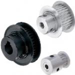
Timing Belt Pulleys / S3M / Flanged Pulley Selectable / Configurable / Material Selectable / Treatment Selectable (Part Numbers - CAD Download)
- Order quantities extended (D-JIT)
(i)Remark
- Please note that the swaged flange options, NFC, RFC, and LFC, are not reflected in the CAD data.

Part Number
Once your search is narrowed to one product,
the corresponding part number is displayed here.
- Drawing / Specifications
- 3D Preview 3D preview is available after complete configuration
- Part Numbers
- More Information
- Catalog
- Technical Information
■S3M
● Pulley Shape
Standard Tooth Profile
Shape K
[ ! ]
Shape A
[ ! ]
Shape B

| mm | Nominal | ||
| S3M060 | S3M100 | S3M150 | |
| A | 7 | 11 | 17 |
| W | 11 | 15 | 21 |
| L | 19 | 23 | 29 |
| dH7 Shaft Bore I.D. | M (Coarse) | Accessory Set Screws |
| 4 to 5 | M3 | M3 × 3 |
| 6 to 17 | M4 | M4 × 3 |
| 18 to 33 | M5 | M5 × 4 |
| 34 to 46 | M6 | M6 × 5 |
[ ! ] Shaft Bore Specs. H (Round hole), V or F (Stepped Hole), Y (Both Sides Stepped Hole) and WB (Two-stepped Hole) do not have tapped holes.
[ ! ] The tolerance of the tap position dimension from the boss end face and pulley end face is ±0.3.
[ ! ] Unless otherwise specified except for teeth and F dimensions, the dimension tolerance conforms to JIS B 0405 Class m.
● Shaft Bore Specification
Select shaft bore spec mark and each dim. from the table below.
[ ! ] Surface treatment may not be applied to the shaft bores.
H round hole
P Round Hole + Tap
N New JIS Keyway + Tap
C Old JIS Keyway + Tap

[ ! ] For A-Shape pulley, the screw holes are set at around 120° to keep away from peaks.
[ ! ] Shaft Bore Specs. P is not available for Shape A with 22 or less teeth and nominal width 060.
V Stepped Hole
F Stepped Hole (Counterbored Hole on the Hub Side)
Y Both Ends Stepped Hole
WB Two-stepped hole

[NG] Not applicable to Shape K
[ ! ] Z - d ≥ 2
[ ! ] 2.0 ≤ J ≤ W-2.0
[ ! ] Applicable to Shape B only
[ ! ] Z - d ≥ 2
[ ! ] 2.0 ≤ J ≤ L-2.0
[ ! ] Applicable to Shape A only
[ ! ] Q (R)-Y ≥ 2
[ ! ] S+T ≤ W-3.0
[ ! ] Shaft Bore Dia. d is +0.1 / 0
[ ! ] S (T) ≥ 3.0
[ ! ] Applicable to Shape A only
[ ! ] Q-R ≥ 2
[ ! ] R-WB ≥ 2
[ ! ] S+T ≤ W-3.0
[ ! ] S (T) ≥ 3.0
| Type | Belt Width | [M] Material | [S] Surface Treatment | [A] Accessory Set Screws | |||
| 6 mm | 10 mm | 15 mm | Pulley | Flange | |||
| S3M060 | S3M100 | S3M150 | |||||
| HTPA | ● | ● | ● | Aluminum alloy | Aluminum alloy | Clear Anodize | EN 1.4301 Equiv. |
| HTPB | ● | ● | ● | Black Anodize | |||
| HTPK | ● | ● | ● | Hard Clear Anodize | |||
| HTPN | ● | ● | ● | Electroless nickel plating | |||
| HTPT | ● | ● | ● | EN 1.1191 Equiv. | EN 1.0330 Equiv. | — | EN 1.7220 Equiv. (Black Oxide) |
| HTPM | ● | ● | ● | Black Oxide Coating | |||
| HTPP | ● | ● | ● | Electroless nickel plating | |||
| HTPS | ● | ● | ● | EN 1.4301 Equiv. | EN 1.4301 Equiv. | — | EN 1.4301 Equiv. |
Specification Table
| Part number | — | Pulley Shape | — | Shaft Bore Specs.: I.D. | — | Z | — | J | — | Q | — | R | — | S | — | T | |
| (Shaft Bore Specs.: H, P, N, C) | HTPA32S3M100 | — | A | — | C16 | ||||||||||||
| (Shaft Bore Specs.: V, F) | HTPA48S3M150 | — | A | — | V12 | — | Z26 | — | J17.0 | ||||||||
| (Shaft Bore Specs.: Y, WB) | HTPA36S3M100 | — | A | — | Y10 | — | Q19 | — | R15 | — | S5 | — | T4 |
| Part number | Pulley Shape | Pulley Shape | P.D. | O.D | D | F | E | |||||||
| Type | Number of Teeth | Type Nominal Width | A | B·K | ||||||||||
| Shaft Bore Specs. | ||||||||||||||
| H Round Hole V·Y·WB Stepped Hole | P Round Hole Tapped | N·C Keyway Tapped | H Round Hole V·F Stepped Hole | P Round Hole Tapped | N·C Keyway Tapped | |||||||||
| d1 mm increments / Selectable | ||||||||||||||
| Aluminum HTPA HTPB HTPK HTPN Steel HTPT HTPM HTPP Stainless Steel HTPS | 14 | S3M060 S3M100 S3M150 | A K | 4 to 6 | 4 | — | 4 to 6 | 4 to 6 | — | 13.37 | 12.61 | 16 | 16 | 10 |
| 15 | 4 to 7 | 4 to 5 | 14.32 | 13.56 | 18 | 18 | 11 | |||||||
| 16 | 4 to 7 | 4 to 7 | 15.28 | 14.52 | ||||||||||
| 17 | 4 to 9 | 4 to 6 | 4 to 8 | 4 to 8 | 16.23 | 15.47 | 20 | 20 | 13 | |||||
| 18 | 17.19 | 16.43 | ||||||||||||
| 19 | 4 to 10 | 18.14 | 17.38 | 22 | 22 | 14 | ||||||||
| 20 | 19.10 | 18.34 | ||||||||||||
| 21 | 4 to 12 | 4 to 8 | 4 to 10 | 4 to 10 | 20.05 | 19.29 | 25 | 25 | 16 | |||||
| 22 | 21.01 | 20.25 | ||||||||||||
| 23 | 4 to 10 | 4 to 8 | 21.96 | 21.20 | ||||||||||
| 24 | A B | 22.92 | 22.16 | 14 | 25 | 16 | ||||||||
| 25 | 4 to 14 | 4 to 11 | 8 to 11 | 4 to 12 | 4 to 10 | 8 | 23.87 | 23.11 | 16 | 28 | 18 | |||
| 26 | 5 to 14 | 5 to 11 | 5 to 12 | 5 to 10 | 24.83 | 24.07 | ||||||||
| 27 | 5 to 16 | 5 to 13 | 8 to 13 | 5 to 14 | 25.78 | 25.02 | 18 | 30 | 20 | |||||
| 28 | 26.74 | 25.98 | ||||||||||||
| 29 | 6 to 19 | 6 to 15 | 8 to 14 | 6 to 16 | 6 to 12 | 8 to 11 | 27.69 | 26.93 | 20 | 32 | 23 | |||
| 30 | 28.65 | 27.89 | ||||||||||||
| 31 | 6 to 21 | 6 to 17 | 8 to 17 | 29.60 | 28.84 | 35 | 25 | |||||||
| 32 | 30.56 | 29.80 | ||||||||||||
| 33 | 31.51 | 30.75 | ||||||||||||
| 34 | 6 to 24 | 6 to 18 | 8 to 18 | 6 to 22 | 6 to 18 | 8 to 15 | 32.47 | 31.71 | 26 | 40 | 28 | |||
| 35 | 33.42 | 32.66 | ||||||||||||
| 36 | 8 to 19 | 34.38 | 33.62 | |||||||||||
| 37 | 35.33 | 34.57 | ||||||||||||
| 38 | 8 to 28 | 8 to 23 | 8 to 23 | 8 to 26 | 8 to 21 | 8 to 17 | 36.29 | 35.53 | 30 | 44 | 32 | |||
| 39 | 37.24 | 36.48 | ||||||||||||
| 40 | 38.20 | 37.44 | ||||||||||||
| 41 | 39.15 | 38.39 | ||||||||||||
| 42 | 8 to 32 | 8 to 26 | 8 to 25 | 8 to 28 | 8 to 23 | 8 to 18 | 40.11 | 39.35 | 32 | 48 | 36 | |||
| 43 | 41.06 | 40.30 | ||||||||||||
| 44 | 42.02 | 41.25 | ||||||||||||
| 45 | 42.97 | 42.21 | ||||||||||||
| 46 | 43.93 | 43.16 | ||||||||||||
| 47 | 8 to 34 | 8 to 28 | 8 to 27 | 8 to 30 | 8 to 25 | 8 to 20 | 44.88 | 44.12 | 34 | 50 | 38 | |||
| 48 | 45.84 | 45.07 | ||||||||||||
| 49 | 8 to 36 | 8 to 30 | 8 to 29 | 46.79 | 46.03 | 52 | 40 | |||||||
| 50 | 47.75 | 46.98 | ||||||||||||
| 51 | 48.70 | 47.94 | ||||||||||||
| 52 | 8 to 32 | 8 to 27 | 8 to 21 | 49.66 | 48.89 | 36 | 55 | |||||||
| 53 | 50.61 | 49.85 | ||||||||||||
| 54 | 51.57 | 50.80 | ||||||||||||
| 55 | 8 to 42 | 8 to 34 | 8 to 35 | 8 to 35 | 8 to 30 | 8 to 22 | 52.52 | 51.76 | 39 | 61 | 46 | |||
| 56 | 53.48 | 52.71 | ||||||||||||
| 57 | 54.43 | 53.67 | ||||||||||||
| 58 | 55.39 | 54.62 | ||||||||||||
| 59 | 56.34 | 55.58 | ||||||||||||
| 60 | 57.30 | 56.53 | ||||||||||||
| 72 | 8 to 54 | 8 to 46 | 8 to 45 | 8 to 46 | 8 to 38 | 8 to 33 | 68.75 | 67.99 | 50 | 74 | 58 | |||
| [!] Shaft Bore Dia.4.5 and 6.35are selectable for Shaft Bore Specs. H, P, V and F. [NG] Shaft Bore Specs. P is not available for Shape A with 22 or less teeth and nominal width S3M060. [NG] Shaft Bore Dia.9 is not available for Shaft Bore Spec. N. [NG] Shaft Bore Dia. 8, 11, 13, 14, 17, 21 to 45 are not available for Shaft Bore Spec. C. | ||||||||||||||
Alterations
| Part number | — | Pulley Shape | — | Shaft Bore Specs.: I.D. | — | Z | — | J | — | Q | — | R | — | S | — | T | — | (KC90, etc.) | ||||||||
| HTPA60S3M100 | — | A | — | H16 | — | KSC25 | — | K4 | ||||||||||||||||||
| Alterations | Set Screw Angle Change | No Flange | Single Flange | Flange Cut |
| Code | KC90 | NFC | RFC·LFC | FC |
| Spec. | Changes an angle of set screw to 90°. [ ! ] For A-Shape pulley, the screw holes are set at around 90° to keep away from peaks.  | (Flange 2 pcs. Included) Ordering Code NFC  | (Flange 1 pc. Included) Ordering Code RFC Application Notes [NG] Not applicable to Shape K  | Cut the flange O.D. in 0.5 mm increments. Ordering Code FC17 Application Notes [ ! ]FC ≥ (O. D.) +1 [ ! ]FC ≤ F−2 [ ! ] No surface treatment is applied on flange circumference.  |
| Alterations | Retaining Ring Groove | Taper for Bearing Holder | Hub Shortening | Tapped Hole Dimensions | Included Set Screw Length Change | ||||||||||||||||||||
| Code | SRG | BTC | BC | TPC | SLH | ||||||||||||||||||||
| Spec. | Retaining Ring Groove applicable to the shaft dia. of stepped hole is machined. Specify SRG 2.5 to 14.5 mm [ ! ] Minimum Thickness: 2 mm [ ! ] Applicable to Shaft Bore Specs. V and F only [ ! ] Standards of retaining ring groove for Z dim. is applied [ ! ] n ≤ J−SRG−mOrdering Code SRG7  | Taper for retaining bearing inner ring Ordering Code BTC4-TL1.5 Application Notes [ ! ] Applicable to Shape A only [ ! ] Applicable to Shaft Bore Specs. H and P only [ ! ]TL < L−W [ ! ] When E-D ≤ 6, one side installed and 1 pc. of flange included  | Cuts the hub length in 0.5 mm increments. Ordering Code BC6.5 Application Notes [!] Shaft Bore Specs. H, V, F: 3 ≤ BC < L-W [!] Shaft Bore Specs. P, N, C: M+3 ≤ BC < L−W [NG] Not applicable to Shape K and A  | Ordering Code TPC5 Application Notes [ ! ] Applicable to Shaft Bore Specs. P, N, C only
| Ordering Code SLH10 Application Notes [ ! ] Applicable to Shaft Bore Specs. P, N, C only
|
| Alterations | Add Side Holes [!] Conditions may vary depending on the shaft bore specs. | ||
| Side Tapped Hole | Side Through Hole | Side Counterbored | |
| Code | QTC·QFC·QSC | KTC·KFC·KSC | ZTC·ZFC·ZSC |
| Spec. | Machines tapped hole on the side surface of hub side. Ordering Code QTC28−M4 Q□C Selection Specify the hole position (P. C. D. dim.). M Selection M3, M4, M5, M6, M8 Application Notes [NG] Not applicable to Shape K [ ! ] Minimum Thickness: 2 mm [!] Conditions may vary depending on the shaft bore specs. (6 Locations) (4 Locations) (3 Locations)  | Machines through hole on the side surface. Ordering Code KTC28−K4.5 K□C Selection Specify the hole position (P. C. D. dim.). Specify K K4.0 to 13.0 (0.5 mm Increments) Application Notes [NG] Not applicable to Shape K [ ! ] Minimum Thickness: 2 mm [!] Conditions may vary depending on the shaft bore specs. (6 Locations) (4 Locations) (3 Locations)  | Machines counterbored hole on the side surface. Ordering Code ZTC28−ZM4 Z□C Selection Specify the hole position (P. C. D. dim.). ZM Selection ZM3, ZM4, ZM5, ZM6, ZM8 Application Notes [NG] Not applicable to Shape K [ ! ] Minimum Thickness: 2 mm [!] Conditions may vary depending on the shaft bore specs. (6 Locations) (4 Locations) (3 Locations)  |
Part Number:
- In order to open the 3D preview, the part number must be fixed.
3D preview is not available, because the part number has not yet been determined.
| Part Number |
Standard Unit Price
| Minimum order quantity | Volume Discount | RoHS | Belt Width (mm) | [T] Number of Teeth | Pulley Shape | Material | Surface Treatment | [Y] Shaft Bore Specification (Both Ends Stepped Hole) (mm) | [N] Shaft Bore Specification (New JIS Keyway Hole + Tap) (mm) | [C] Shaft Bore Specification (Old JIS Keyway Hole + Tap) (mm) | [P] Shaft Bore Specification (Round Hole + Tap) (mm) | [H] Shaft Bore Specification (Round Hole) (mm) | [NK] Shaft Bore Specification (Shaft Bore Dia. 10 Keyway Width 4mm Height 1.8mm) | [V] Shaft Bore Specification (Stepped Hole) (mm) | [F] Shaft Bore Specification (Stepped Hole: Counterbored Holes on the Hub Side) (mm) | [WB] Shaft Bore Specification (Two-Stepped Hole on one side) (mm) | |
|---|---|---|---|---|---|---|---|---|---|---|---|---|---|---|---|---|---|---|---|
- | 1 | 6 Days | - | 6 | 29 | Shape B | [Aluminum] Aluminum Alloy | Clear Anodize | - | - | - | - | 6 ~ 16 | - | - | - | - | ||
- | 1 | 6 Days | - | 6 | 29 | Shape B | [Aluminum] Aluminum Alloy | Clear Anodize | - | 8 | - | - | - | - | - | - | - | ||
- | 1 | 6 Days | - | 6 | 29 | Shape B | [Aluminum] Aluminum Alloy | Clear Anodize | - | - | - | - | - | 10 | - | - | - | ||
- | 1 | 6 Days | - | 6 | 29 | Shape B | [Aluminum] Aluminum Alloy | Clear Anodize | - | - | - | 6.35 | - | - | - | - | - | ||
- | 1 | 6 Days | - | 6 | 29 | Shape B | [Aluminum] Aluminum Alloy | Clear Anodize | - | - | - | 6 ~ 12 | - | - | - | - | - | ||
- | 1 | 6 Days | - | 6 | 29 | Shape B | [Aluminum] Aluminum Alloy | Clear Anodize | - | - | - | - | - | - | 6.35 | - | - | ||
- | 1 | 6 Days | - | 6 | 29 | Shape B | [Aluminum] Aluminum Alloy | Clear Anodize | - | - | - | - | - | - | 6 ~ 14 | - | - | ||
- | 1 | 6 Days | - | 10 | 29 | Shape A | [Aluminum] Aluminum Alloy | Clear Anodize | - | - | 10 ~ 12 | - | - | - | - | - | - | ||
- | 1 | 6 Days | - | 10 | 29 | Shape A | [Aluminum] Aluminum Alloy | Clear Anodize | - | - | - | - | 6 ~ 19 | - | - | - | - | ||
- | 1 | 6 Days | - | 10 | 29 | Shape A | [Aluminum] Aluminum Alloy | Clear Anodize | - | 8 | - | - | - | - | - | - | - | ||
- | 1 | 6 Days | - | 10 | 29 | Shape A | [Aluminum] Aluminum Alloy | Clear Anodize | - | - | - | - | - | 10 | - | - | - | ||
- | 1 | 6 Days | - | 10 | 29 | Shape A | [Aluminum] Aluminum Alloy | Clear Anodize | - | - | - | 6.35 | - | - | - | - | - | ||
- | 1 | 6 Days | - | 10 | 29 | Shape A | [Aluminum] Aluminum Alloy | Clear Anodize | - | - | - | 6 ~ 15 | - | - | - | - | - | ||
- | 1 | 6 Days | - | 10 | 29 | Shape A | [Aluminum] Aluminum Alloy | Clear Anodize | - | - | - | - | - | - | 6 ~ 17 | - | - | ||
- | 1 | 6 Days | - | 10 | 29 | Shape A | [Aluminum] Aluminum Alloy | Clear Anodize | - | - | - | - | - | - | - | - | 6 ~ 17 | ||
- | 1 | 6 Days | - | 10 | 29 | Shape A | [Aluminum] Aluminum Alloy | Clear Anodize | 6 ~ 17 | - | - | - | - | - | - | - | - | ||
- | 1 | 6 Days | - | 10 | 29 | Shape B | [Aluminum] Aluminum Alloy | Clear Anodize | - | - | - | - | - | - | - | 6.35 | - | ||
- | 1 | 6 Days | - | 10 | 29 | Shape B | [Aluminum] Aluminum Alloy | Clear Anodize | - | - | - | - | - | - | - | 6 ~ 14 | - | ||
- | 1 | 6 Days | - | 10 | 29 | Shape B | [Aluminum] Aluminum Alloy | Clear Anodize | - | - | - | - | 6.35 | - | - | - | - | ||
- | 1 | 6 Days | - | 10 | 29 | Shape B | [Aluminum] Aluminum Alloy | Clear Anodize | - | - | - | - | 6 ~ 16 | - | - | - | - | ||
- | 1 | 6 Days | - | 10 | 29 | Shape B | [Aluminum] Aluminum Alloy | Clear Anodize | - | 8 | - | - | - | - | - | - | - | ||
- | 1 | 6 Days | - | 10 | 29 | Shape B | [Aluminum] Aluminum Alloy | Clear Anodize | - | - | - | - | - | 10 | - | - | - | ||
- | 1 | 6 Days | - | 10 | 29 | Shape B | [Aluminum] Aluminum Alloy | Clear Anodize | - | - | - | 6.35 | - | - | - | - | - | ||
- | 1 | 6 Days | - | 10 | 29 | Shape B | [Aluminum] Aluminum Alloy | Clear Anodize | - | - | - | 6 ~ 12 | - | - | - | - | - | ||
- | 1 | 6 Days | - | 10 | 29 | Shape B | [Aluminum] Aluminum Alloy | Clear Anodize | - | - | - | - | - | - | 6.35 | - | - | ||
- | 1 | 6 Days | - | 10 | 29 | Shape B | [Aluminum] Aluminum Alloy | Clear Anodize | - | - | - | - | - | - | 6 ~ 14 | - | - | ||
- | 1 | 6 Days | - | 15 | 29 | Shape A | [Aluminum] Aluminum Alloy | Clear Anodize | - | - | 10 ~ 12 | - | - | - | - | - | - | ||
- | 1 | 6 Days | - | 15 | 29 | Shape A | [Aluminum] Aluminum Alloy | Clear Anodize | - | - | - | - | 6 ~ 19 | - | - | - | - | ||
- | 1 | 6 Days | - | 15 | 29 | Shape A | [Aluminum] Aluminum Alloy | Clear Anodize | - | 8 | - | - | - | - | - | - | - | ||
- | 1 | 6 Days | - | 15 | 29 | Shape A | [Aluminum] Aluminum Alloy | Clear Anodize | - | - | - | - | - | 10 | - | - | - | ||
- | 1 | 6 Days | - | 15 | 29 | Shape A | [Aluminum] Aluminum Alloy | Clear Anodize | - | - | - | 6.35 | - | - | - | - | - | ||
- | 1 | 6 Days | - | 15 | 29 | Shape A | [Aluminum] Aluminum Alloy | Clear Anodize | - | - | - | 6 ~ 15 | - | - | - | - | - | ||
- | 1 | 6 Days | - | 15 | 29 | Shape A | [Aluminum] Aluminum Alloy | Clear Anodize | - | - | - | - | - | - | 6 ~ 17 | - | - | ||
- | 1 | 6 Days | - | 15 | 29 | Shape A | [Aluminum] Aluminum Alloy | Clear Anodize | - | - | - | - | - | - | - | - | 6 ~ 17 | ||
- | 1 | 6 Days | - | 15 | 29 | Shape A | [Aluminum] Aluminum Alloy | Clear Anodize | 6 ~ 17 | - | - | - | - | - | - | - | - | ||
- | 1 | 6 Days | - | 15 | 29 | Shape B | [Aluminum] Aluminum Alloy | Clear Anodize | - | - | - | - | - | - | - | 6.35 | - | ||
- | 1 | 6 Days | - | 15 | 29 | Shape B | [Aluminum] Aluminum Alloy | Clear Anodize | - | - | - | - | - | - | - | 6 ~ 14 | - | ||
- | 1 | 6 Days | - | 15 | 29 | Shape B | [Aluminum] Aluminum Alloy | Clear Anodize | - | - | - | - | 6.35 | - | - | - | - | ||
- | 1 | 6 Days | - | 15 | 29 | Shape B | [Aluminum] Aluminum Alloy | Clear Anodize | - | - | - | - | 6 ~ 16 | - | - | - | - | ||
- | 1 | 6 Days | - | 15 | 29 | Shape B | [Aluminum] Aluminum Alloy | Clear Anodize | - | 8 | - | - | - | - | - | - | - | ||
- | 1 | 6 Days | - | 15 | 29 | Shape B | [Aluminum] Aluminum Alloy | Clear Anodize | - | - | - | - | - | 10 | - | - | - | ||
- | 1 | 6 Days | - | 15 | 29 | Shape B | [Aluminum] Aluminum Alloy | Clear Anodize | - | - | - | 6.35 | - | - | - | - | - | ||
- | 1 | 6 Days | - | 15 | 29 | Shape B | [Aluminum] Aluminum Alloy | Clear Anodize | - | - | - | 6 ~ 12 | - | - | - | - | - | ||
- | 1 | 6 Days | - | 15 | 29 | Shape B | [Aluminum] Aluminum Alloy | Clear Anodize | - | - | - | - | - | - | 6.35 | - | - | ||
- | 1 | 6 Days | - | 15 | 29 | Shape B | [Aluminum] Aluminum Alloy | Clear Anodize | - | - | - | - | - | - | 6 ~ 14 | - | - | ||
- | 1 | 6 Days | 10 | 6 | 30 | Shape A | [Aluminum] 2000 Series Aluminum Alloy (Duralumin) | Clear Anodize | - | - | 10 ~ 12 | - | - | - | - | - | - | ||
- | 1 | 6 Days | 10 | 6 | 30 | Shape A | [Aluminum] 2000 Series Aluminum Alloy (Duralumin) | Clear Anodize | - | - | - | - | 6.35 | - | - | - | - | ||
- | 1 | 6 Days | 10 | 6 | 30 | Shape A | [Aluminum] 2000 Series Aluminum Alloy (Duralumin) | Clear Anodize | - | - | - | - | 6 ~ 15 | - | - | - | - | ||
- | 1 | 6 Days | 10 | 6 | 30 | Shape A | [Aluminum] 2000 Series Aluminum Alloy (Duralumin) | Clear Anodize | - | 8 ~ 14 | - | - | - | - | - | - | - | ||
- | 1 | 6 Days | 10 | 6 | 30 | Shape A | [Aluminum] 2000 Series Aluminum Alloy (Duralumin) | Clear Anodize | - | - | - | - | - | 10 | - | - | - | ||
- | 1 | 6 Days | 10 | 6 | 30 | Shape A | [Aluminum] 2000 Series Aluminum Alloy (Duralumin) | Clear Anodize | - | - | - | 6.35 | - | - | - | - | - | ||
- | 1 | 6 Days | 10 | 6 | 30 | Shape A | [Aluminum] 2000 Series Aluminum Alloy (Duralumin) | Clear Anodize | - | - | - | 6 ~ 14 | - | - | - | - | - | ||
- | 1 | 6 Days | 10 | 6 | 30 | Shape A | [Aluminum] 2000 Series Aluminum Alloy (Duralumin) | Clear Anodize | - | - | - | - | - | - | 6.35 | - | - | ||
- | 1 | 6 Days | 10 | 6 | 30 | Shape A | [Aluminum] 2000 Series Aluminum Alloy (Duralumin) | Clear Anodize | - | - | - | - | - | - | 6 ~ 13 | - | - | ||
- | 1 | 6 Days | 10 | 6 | 30 | Shape A | [Aluminum] 2000 Series Aluminum Alloy (Duralumin) | Clear Anodize | 6 ~ 13 | - | - | - | - | - | - | - | - | ||
- | 1 | 6 Days | 10 | 6 | 30 | Shape B | [Aluminum] 2000 Series Aluminum Alloy (Duralumin) | Clear Anodize | - | - | 10 | - | - | - | - | - | - | ||
- | 1 | 6 Days | 10 | 6 | 30 | Shape B | [Aluminum] 2000 Series Aluminum Alloy (Duralumin) | Clear Anodize | - | - | - | - | - | - | - | 6.35 | - | ||
- | 1 | 6 Days | 10 | 6 | 30 | Shape B | [Aluminum] 2000 Series Aluminum Alloy (Duralumin) | Clear Anodize | - | - | - | - | - | - | - | 6 ~ 13 | - | ||
- | 1 | 6 Days | 10 | 6 | 30 | Shape B | [Aluminum] 2000 Series Aluminum Alloy (Duralumin) | Clear Anodize | - | - | - | - | 6.35 | - | - | - | - | ||
- | 1 | 6 Days | 10 | 6 | 30 | Shape B | [Aluminum] 2000 Series Aluminum Alloy (Duralumin) | Clear Anodize | - | - | - | - | 6 ~ 15 | - | - | - | - |
Loading...
Specifications/Overview
Basic information
| Type | Timing Pulleys | Belt Type | S3M | Timing Pulleys/Idlers | Pulleys |
|---|
Configure
Basic Attributes
-
Belt Width(mm)
-
[T] Number of Teeth
-
Pulley Shape
- Shape A
- Shape B
- Shape K
-
Material
- EN 1.1191 Equiv.
- Aluminum
- EN 1.4301 Equiv.
-
[Y] Shaft Bore Specification (Both Ends Stepped Hole)(mm)
-
[N] Shaft Bore Specification (New JIS Keyway Hole + Tap)(mm)
-
[C] Shaft Bore Specification (Old JIS Keyway Hole + Tap)(mm)
-
[P] Shaft Bore Specification (Round Hole + Tap)(mm)
-
[H] Shaft Bore Specification (Round Hole)(mm)
-
[NK] Shaft Bore Specification (Shaft Bore Dia. 10 Keyway Width 4mm Height 1.8mm)
-
[V] Shaft Bore Specification (Stepped Hole)(mm)
-
[F] Shaft Bore Specification (Stepped Hole: Counterbored Holes on the Hub Side)(mm)
-
[WB] Shaft Bore Specification (Two-Stepped Hole on one side)(mm)
-
Type
- HTPA□□S3M
- HTPB□□S3M
- HTPK□□S3M
- HTPM□□S3M
- HTPN□□S3M
- HTPP□□S3M
- HTPS□□S3M
- HTPT□□S3M
-
Surface Treatment
- Not Provided
- Black Oxide
- Clear Anodize
- Black Anodized Aluminum
- Hard Clear Anodize
- Electroless Nickel Plating
-
Filter by CAD data type
- 2D
- 3D
Filter by standard shipping days
-
- All
- 6 Days or Less
- 7 Days or Less
- 8 Days or Less
- 12 Days or Less
Optional Attributes
- The specifications and dimensions of some parts may not be fully covered. For exact details, refer to manufacturer catalogs .
Complementary Products
-
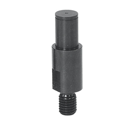 Cantilever Shafts / shouldered / external thread, ring groove / spanner flat
MISUMI Shipping Days: 3 Days
-
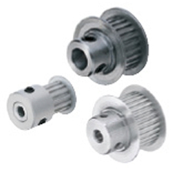 Timing belt pulleys / MXL / flanged pulley selectable / configurable / material selectable / treatment selectable
MISUMI Shipping Days: 6 Days
-
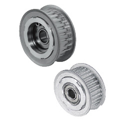 Tensioner Idlers / toothed / MXL, XL / flanged pulley selectable / single bearing, double bearing / aluminium
MISUMI Standard Price : 24.43 € Shipping Days: 6 Days


MISUMI Unit еxample related to this product


Tech Support
Payment Method


On-Demand Manufacturing
Certificates


Copyright © MISUMI Corporation All Rights Reserved.