Timing Belt Pulleys / S3M / Flanged Pulley Selectable / Configurable / Material Selectable / Treatment Selectable (Part Numbers - CAD Download)
- Order quantities extended (D-JIT)
(i)Remark
- Please note that the swaged flange options, NFC, RFC, and LFC, are not reflected in the CAD data.

Part Number
Once your search is narrowed to one product,
the corresponding part number is displayed here.
- Drawing / Specifications
- 3D Preview 3D preview is available after complete configuration
- Part Numbers
- More Information
- Catalog
- Technical Information
Back to the Category Toothed Pulleys/Timing Pulleys/Idler Pulleys
Technical Drawing - Toothed Pulleys/Timing Pulleys/Idler Pulleys
■S3M
● Pulley Shape
Standard Tooth Profile
Shape K
[ ! ]
Shape A
[ ! ]
Shape B

Open the technical drawing in the new window
Available dimensions and tolerances can be found under the tab More Information.
Basic Properties (e.g., material, hardness, coating, tolerance) - Toothed Pulleys/Timing Pulleys/Idler Pulleys
| mm | Nominal | ||
| S3M060 | S3M100 | S3M150 | |
| A | 7 | 11 | 17 |
| W | 11 | 15 | 21 |
| L | 19 | 23 | 29 |
| dH7 Shaft Bore I.D. | M (Coarse) | Accessory Set Screws |
| 4 to 5 | M3 | M3 × 3 |
| 6 to 17 | M4 | M4 × 3 |
| 18 to 33 | M5 | M5 × 4 |
| 34 to 46 | M6 | M6 × 5 |
[ ! ] Shaft Bore Specs. H (Round hole), V or F (Stepped Hole), Y (Both Sides Stepped Hole) and WB (Two-stepped Hole) do not have tapped holes.
[ ! ] The tolerance of the tap position dimension from the boss end face and pulley end face is ±0.3.
[ ! ] Unless otherwise specified except for teeth and F dimensions, the dimension tolerance conforms to JIS B 0405 Class m.
● Shaft Bore Specification
Select shaft bore spec mark and each dim. from the table below.
[ ! ] Surface treatment may not be applied to the shaft bores.
H round hole
P Round Hole + Tap
N New JIS Keyway + Tap
C Old JIS Keyway + Tap

[ ! ] For A-Shape pulley, the screw holes are set at around 120° to keep away from peaks.
[ ! ] Shaft Bore Specs. P is not available for Shape A with 22 or less teeth and nominal width 060.
V Stepped Hole
F Stepped Hole (Counterbored Hole on the Hub Side)
Y Both Ends Stepped Hole
WB Two-stepped hole

[NG] Not applicable to Shape K
[ ! ] Z - d ≥ 2
[ ! ] 2.0 ≤ J ≤ W-2.0
[ ! ] Applicable to Shape B only
[ ! ] Z - d ≥ 2
[ ! ] 2.0 ≤ J ≤ L-2.0
[ ! ] Applicable to Shape A only
[ ! ] Q (R)-Y ≥ 2
[ ! ] S+T ≤ W-3.0
[ ! ] Shaft Bore Dia. d is +0.1 / 0
[ ! ] S (T) ≥ 3.0
[ ! ] Applicable to Shape A only
[ ! ] Q-R ≥ 2
[ ! ] R-WB ≥ 2
[ ! ] S+T ≤ W-3.0
[ ! ] S (T) ≥ 3.0
| Type | Belt Width | [M] Material | [S] Surface Treatment | [A] Accessory Set Screws | |||
| 6 mm | 10 mm | 15 mm | Pulley | Flange | |||
| S3M060 | S3M100 | S3M150 | |||||
| HTPA | ● | ● | ● | Aluminum alloy | Aluminum alloy | Clear Anodize | EN 1.4301 Equiv. |
| HTPB | ● | ● | ● | Black Anodize | |||
| HTPK | ● | ● | ● | Hard Clear Anodize | |||
| HTPN | ● | ● | ● | Electroless nickel plating | |||
| HTPT | ● | ● | ● | EN 1.1191 Equiv. | EN 1.0330 Equiv. | — | EN 1.7220 Equiv. (Black Oxide) |
| HTPM | ● | ● | ● | Black Oxide Coating | |||
| HTPP | ● | ● | ● | Electroless nickel plating | |||
| HTPS | ● | ● | ● | EN 1.4301 Equiv. | EN 1.4301 Equiv. | — | EN 1.4301 Equiv. |
Further specifications can be found under the tab More Information.
Composition of a Product Code - Toothed Pulleys/Timing Pulleys/Idler Pulleys
| Part number | — | Pulley Shape | — | Shaft Bore Specs.: I.D. | — | Z | — | J | — | Q | — | R | — | S | — | T | |
| (Shaft Bore Specs.: H, P, N, C) | HTPA32S3M100 | — | A | — | C16 | ||||||||||||
| (Shaft Bore Specs.: V, F) | HTPA48S3M150 | — | A | — | V12 | — | Z26 | — | J17.0 | ||||||||
| (Shaft Bore Specs.: Y, WB) | HTPA36S3M100 | — | A | — | Y10 | — | Q19 | — | R15 | — | S5 | — | T4 |
Alterations - Toothed Pulleys/Timing Pulleys/Idler Pulleys
| Part number | — | Pulley Shape | — | Shaft Bore Specs.: I.D. | — | Z | — | J | — | Q | — | R | — | S | — | T | — | (KC90, etc.) | ||||||||
| HTPA60S3M100 | — | A | — | H16 | — | KSC25 | — | K4 | ||||||||||||||||||
| Alterations | Set Screw Angle Change | No Flange | Single Flange | Flange Cut |
| Code | KC90 | NFC | RFC·LFC | FC |
| Spec. | Changes an angle of set screw to 90°. [ ! ] For A-Shape pulley, the screw holes are set at around 90° to keep away from peaks.  | (Flange 2 pcs. Included) Ordering Code NFC  | (Flange 1 pc. Included) Ordering Code RFC Application Notes [NG] Not applicable to Shape K  | Cut the flange O.D. in 0.5 mm increments. Ordering Code FC17 Application Notes [ ! ]FC ≥ (O. D.) +1 [ ! ]FC ≤ F−2 [ ! ] No surface treatment is applied on flange circumference.  |
| Alterations | Retaining Ring Groove | Taper for Bearing Holder | Hub Shortening | Tapped Hole Dimensions | Included Set Screw Length Change | ||||||||||||||||||||
| Code | SRG | BTC | BC | TPC | SLH | ||||||||||||||||||||
| Spec. | Retaining Ring Groove applicable to the shaft dia. of stepped hole is machined. Specify SRG 2.5 to 14.5 mm [ ! ] Minimum Thickness: 2 mm [ ! ] Applicable to Shaft Bore Specs. V and F only [ ! ] Standards of retaining ring groove for Z dim. is applied [ ! ] n ≤ J−SRG−mOrdering Code SRG7  | Taper for retaining bearing inner ring Ordering Code BTC4-TL1.5 Application Notes [ ! ] Applicable to Shape A only [ ! ] Applicable to Shaft Bore Specs. H and P only [ ! ]TL < L−W [ ! ] When E-D ≤ 6, one side installed and 1 pc. of flange included  | Cuts the hub length in 0.5 mm increments. Ordering Code BC6.5 Application Notes [!] Shaft Bore Specs. H, V, F: 3 ≤ BC < L-W [!] Shaft Bore Specs. P, N, C: M+3 ≤ BC < L−W [NG] Not applicable to Shape K and A  | Ordering Code TPC5 Application Notes [ ! ] Applicable to Shaft Bore Specs. P, N, C only
| Ordering Code SLH10 Application Notes [ ! ] Applicable to Shaft Bore Specs. P, N, C only
|
| Alterations | Add Side Holes [!] Conditions may vary depending on the shaft bore specs. | ||
| Side Tapped Hole | Side Through Hole | Side Counterbored | |
| Code | QTC·QFC·QSC | KTC·KFC·KSC | ZTC·ZFC·ZSC |
| Spec. | Machines tapped hole on the side surface of hub side. Ordering Code QTC28−M4 Q□C Selection Specify the hole position (P. C. D. dim.). M Selection M3, M4, M5, M6, M8 Application Notes [NG] Not applicable to Shape K [ ! ] Minimum Thickness: 2 mm [!] Conditions may vary depending on the shaft bore specs. (6 Locations) (4 Locations) (3 Locations)  | Machines through hole on the side surface. Ordering Code KTC28−K4.5 K□C Selection Specify the hole position (P. C. D. dim.). Specify K K4.0 to 13.0 (0.5 mm Increments) Application Notes [NG] Not applicable to Shape K [ ! ] Minimum Thickness: 2 mm [!] Conditions may vary depending on the shaft bore specs. (6 Locations) (4 Locations) (3 Locations)  | Machines counterbored hole on the side surface. Ordering Code ZTC28−ZM4 Z□C Selection Specify the hole position (P. C. D. dim.). ZM Selection ZM3, ZM4, ZM5, ZM6, ZM8 Application Notes [NG] Not applicable to Shape K [ ! ] Minimum Thickness: 2 mm [!] Conditions may vary depending on the shaft bore specs. (6 Locations) (4 Locations) (3 Locations)  |
Here to the Overview of Options as PDF.
General Information - Toothed Pulleys/Timing Pulleys/Idler Pulleys
Selection details of toothed pulleys/timing pulleys/idler pulleys
- Material: aluminum, steel, stainless steel (stainless steel), plastic
- Coatings: uncoated, burnished, anodized, nickel-plated
- Profile form: 1.5GT, 2GT, 3GT, 5GT, P2M, P3M, P5M, P8M, S2M, S3M, S5M, S8M, S14M, T2.5, T5, T10, AT5, AT10, 5M, 8M, 14M, 8YU, H, L, MXL, XL, PowerGrip GT3: MR2, MR3, MR5
- ISO tolerances: H7
- Belt width (mm): 4, 4.8, 6, 6.4, 7, 7.9, 9, 9.5, 10, 12, 12.7, 15, 18, 19.1, 20, 25, 25.4, 26, 28, 30, 31, 38,1, 40, 50, 50.8, 53, 60, 74, 76.2, 100
- Belt width (inches): 0.19, 0.25, 0.31, 0.37, 0.5, 0.75, 1, 1.5, 2
- Number of teeth: 10 to 72
Description/Basics
The toothed pulley for mechanical engineering is intended for the transmission of force and torque. Timing pulleys enable a gear ratio of speeds through belt pulleys of different sizes. Timing pulleys are more efficient, durable and significantly more maintenance-friendly compared to chain transmissions.
How much torque and load a timing pulley can transmit depends on the width of the belt. The width of the belt must be calculated. It is recommended to ensure the belt is correctly tensioned. MISUMI already offers the suitable idler pulley and return rollers with integrated ball bearings. For design and design help follow this link.
Different profile shapes of the toothed belts and belt pulleys are responsible for the transmission of power. Depending on the positioning accuracy, the applied torque and the conveying weight, MISUMI offers the fitting pulley. Toothed belt drives are generally used in the industry in three areas:
Positioning: Timing pulleys is often used in 3D printers. A toothed pulley with a semi-circular profile (e.g., GT) is often used for the required position accuracy of a 3D printers. The round shape offers the benefit of little play when the direction changes.
Drive: toothed pulleys are also used for high torque. In most cases, a timing pulley with a rounded trapezoidal profile (e.g., S8M) is used. These are particularly well suited for the transmission of high forces, which occur in drives of various applications in order to drive mechanical components.
Conveying: toothed pulleys can also be used for transporting loads. A straight trapezoidal profile is often used for this purpose (e.g., AT). This toothed pulley shape offers a large surface for loading and transmitting of loads.
Which toothed pulley or timing pulley is the right one for your application depends on the respective task of the toothed belt drive. Different toothed disc profiles have proven themselves for each type of application.
Various bore hole shapes and fastening variants are available for shaft mounting. These allow fastening via set screws, keyways and by means of Mecha locks. Fastening via a clamping sleeve has the further advantage that it allows adjusting the alignment continuously. The MISUMI product assortment has these ready-to-install.
Application Examples - Toothed Pulleys/Timing Pulleys/Idler Pulleys

Application example: idler pulley
(1) Idler pulleys, (2) chain tensioner
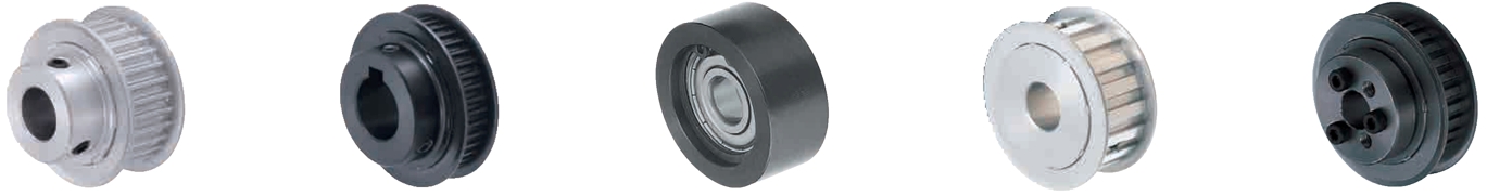
Application example: deflection roller
S (1) Toothed pulleys with crimp disc, (2) nut, (3) washer, (4) cantilever shaft, (5) retaining ring

Application example: timing pulleys
(1) Flat head screw, (2) Timing pulley, (3) Timing belt, (4) Screw-on terminal
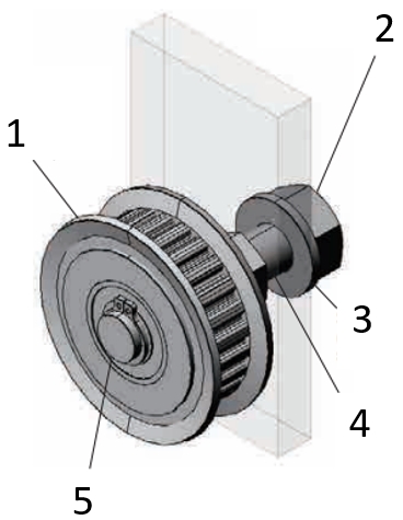
Application example: of toothed belt drives
(1) Toothed belt, (2) driven toothed pulley with crimp disc, (3) idler pulley with crimp disc, (4) driving toothed pulley with crimp disc
Industrial Applications


Part Number:
- In order to open the 3D preview, the part number must be fixed.
3D preview is not available, because the part number has not yet been determined.
| Part Number |
Standard Unit Price
| Minimum order quantity | Volume Discount | RoHS | Belt Width (mm) | [T] Number of Teeth | Pulley Shape | Material | Surface Treatment | [Y] Shaft Bore Specification (Both Ends Stepped Hole) (mm) | [N] Shaft Bore Specification (New JIS Keyway Hole + Tap) (mm) | [C] Shaft Bore Specification (Old JIS Keyway Hole + Tap) (mm) | [P] Shaft Bore Specification (Round Hole + Tap) (mm) | [H] Shaft Bore Specification (Round Hole) (mm) | [NK] Shaft Bore Specification (Shaft Bore Dia. 10 Keyway Width 4mm Height 1.8mm) | [V] Shaft Bore Specification (Stepped Hole) (mm) | [F] Shaft Bore Specification (Stepped Hole: Counterbored Holes on the Hub Side) (mm) | [WB] Shaft Bore Specification (Two-Stepped Hole on one side) (mm) | |
|---|---|---|---|---|---|---|---|---|---|---|---|---|---|---|---|---|---|---|---|
- | 1 | 6 Days | 10 | 15 | 25 | Shape B | [Aluminum] 2000 Series Aluminum Alloy (Duralumin) | Hard Clear Anodize | - | 8 | - | - | - | - | - | - | - | ||
- | 1 | 6 Days | 10 | 15 | 25 | Shape B | [Aluminum] 2000 Series Aluminum Alloy (Duralumin) | Hard Clear Anodize | - | - | - | 6.35 | - | - | - | - | - | ||
- | 1 | 6 Days | 10 | 15 | 25 | Shape B | [Aluminum] 2000 Series Aluminum Alloy (Duralumin) | Hard Clear Anodize | - | - | - | 4 ~ 10 | - | - | - | - | - | ||
- | 1 | 6 Days | 10 | 15 | 25 | Shape B | [Aluminum] 2000 Series Aluminum Alloy (Duralumin) | Hard Clear Anodize | - | - | - | - | - | - | 4 ~ 8 | - | - | ||
- | 1 | 6 Days | 10 | 6 | 26 | Shape A | [Aluminum] 2000 Series Aluminum Alloy (Duralumin) | Hard Clear Anodize | - | - | 10 | - | - | - | - | - | - | ||
- | 1 | 6 Days | 10 | 6 | 26 | Shape A | [Aluminum] 2000 Series Aluminum Alloy (Duralumin) | Hard Clear Anodize | - | - | - | - | 6.35 | - | - | - | - | ||
- | 1 | 6 Days | 10 | 6 | 26 | Shape A | [Aluminum] 2000 Series Aluminum Alloy (Duralumin) | Hard Clear Anodize | - | - | - | - | 5 ~ 11 | - | - | - | - | ||
- | 1 | 6 Days | 10 | 6 | 26 | Shape A | [Aluminum] 2000 Series Aluminum Alloy (Duralumin) | Hard Clear Anodize | - | 8 ~ 11 | - | - | - | - | - | - | - | ||
- | 1 | 6 Days | 10 | 6 | 26 | Shape A | [Aluminum] 2000 Series Aluminum Alloy (Duralumin) | Hard Clear Anodize | - | - | - | - | - | 10 | - | - | - | ||
- | 1 | 6 Days | 10 | 6 | 26 | Shape A | [Aluminum] 2000 Series Aluminum Alloy (Duralumin) | Hard Clear Anodize | - | - | - | 6.35 | - | - | - | - | - | ||
- | 1 | 6 Days | 10 | 6 | 26 | Shape A | [Aluminum] 2000 Series Aluminum Alloy (Duralumin) | Hard Clear Anodize | - | - | - | 5 ~ 11 | - | - | - | - | - | ||
- | 1 | 6 Days | 10 | 6 | 26 | Shape A | [Aluminum] 2000 Series Aluminum Alloy (Duralumin) | Hard Clear Anodize | - | - | - | - | - | - | 5 ~ 8 | - | - | ||
- | 1 | 6 Days | 10 | 6 | 26 | Shape A | [Aluminum] 2000 Series Aluminum Alloy (Duralumin) | Hard Clear Anodize | 5 ~ 8 | - | - | - | - | - | - | - | - | ||
- | 1 | 6 Days | 10 | 6 | 26 | Shape B | [Aluminum] 2000 Series Aluminum Alloy (Duralumin) | Hard Clear Anodize | - | - | - | - | - | - | - | 5 ~ 8 | - | ||
- | 1 | 6 Days | 10 | 6 | 26 | Shape B | [Aluminum] 2000 Series Aluminum Alloy (Duralumin) | Hard Clear Anodize | - | - | - | - | 6.35 | - | - | - | - | ||
- | 1 | 6 Days | 10 | 6 | 26 | Shape B | [Aluminum] 2000 Series Aluminum Alloy (Duralumin) | Hard Clear Anodize | - | - | - | - | 5 ~ 11 | - | - | - | - | ||
- | 1 | 6 Days | 10 | 6 | 26 | Shape B | [Aluminum] 2000 Series Aluminum Alloy (Duralumin) | Hard Clear Anodize | - | 8 | - | - | - | - | - | - | - | ||
- | 1 | 6 Days | 10 | 6 | 26 | Shape B | [Aluminum] 2000 Series Aluminum Alloy (Duralumin) | Hard Clear Anodize | - | - | - | 6.35 | - | - | - | - | - | ||
- | 1 | 6 Days | 10 | 6 | 26 | Shape B | [Aluminum] 2000 Series Aluminum Alloy (Duralumin) | Hard Clear Anodize | - | - | - | 5 ~ 10 | - | - | - | - | - | ||
- | 1 | 6 Days | 10 | 6 | 26 | Shape B | [Aluminum] 2000 Series Aluminum Alloy (Duralumin) | Hard Clear Anodize | - | - | - | - | - | - | 5 ~ 8 | - | - | ||
- | 1 | 6 Days | 10 | 10 | 26 | Shape A | [Aluminum] 2000 Series Aluminum Alloy (Duralumin) | Hard Clear Anodize | - | - | 10 | - | - | - | - | - | - | ||
- | 1 | 6 Days | 10 | 10 | 26 | Shape A | [Aluminum] 2000 Series Aluminum Alloy (Duralumin) | Hard Clear Anodize | - | - | - | - | 6.35 | - | - | - | - | ||
- | 1 | 6 Days | 10 | 10 | 26 | Shape A | [Aluminum] 2000 Series Aluminum Alloy (Duralumin) | Hard Clear Anodize | - | - | - | - | 5 ~ 11 | - | - | - | - | ||
- | 1 | 6 Days | 10 | 10 | 26 | Shape A | [Aluminum] 2000 Series Aluminum Alloy (Duralumin) | Hard Clear Anodize | - | 8 ~ 11 | - | - | - | - | - | - | - | ||
- | 1 | 6 Days | 10 | 10 | 26 | Shape A | [Aluminum] 2000 Series Aluminum Alloy (Duralumin) | Hard Clear Anodize | - | - | - | - | - | 10 | - | - | - | ||
- | 1 | 6 Days | 10 | 10 | 26 | Shape A | [Aluminum] 2000 Series Aluminum Alloy (Duralumin) | Hard Clear Anodize | - | - | - | 6.35 | - | - | - | - | - | ||
- | 1 | 6 Days | 10 | 10 | 26 | Shape A | [Aluminum] 2000 Series Aluminum Alloy (Duralumin) | Hard Clear Anodize | - | - | - | 5 ~ 11 | - | - | - | - | - | ||
- | 1 | 6 Days | 10 | 10 | 26 | Shape A | [Aluminum] 2000 Series Aluminum Alloy (Duralumin) | Hard Clear Anodize | - | - | - | - | - | - | 5 ~ 8 | - | - | ||
- | 1 | 6 Days | 10 | 10 | 26 | Shape A | [Aluminum] 2000 Series Aluminum Alloy (Duralumin) | Hard Clear Anodize | 5 ~ 8 | - | - | - | - | - | - | - | - | ||
- | 1 | 6 Days | 10 | 10 | 26 | Shape B | [Aluminum] 2000 Series Aluminum Alloy (Duralumin) | Hard Clear Anodize | - | - | - | - | - | - | - | 5 ~ 8 | - | ||
- | 1 | 6 Days | 10 | 10 | 26 | Shape B | [Aluminum] 2000 Series Aluminum Alloy (Duralumin) | Hard Clear Anodize | - | - | - | - | 6.35 | - | - | - | - | ||
- | 1 | 6 Days | 10 | 10 | 26 | Shape B | [Aluminum] 2000 Series Aluminum Alloy (Duralumin) | Hard Clear Anodize | - | - | - | - | 5 ~ 11 | - | - | - | - | ||
- | 1 | 6 Days | 10 | 10 | 26 | Shape B | [Aluminum] 2000 Series Aluminum Alloy (Duralumin) | Hard Clear Anodize | - | 8 | - | - | - | - | - | - | - | ||
- | 1 | 6 Days | 10 | 10 | 26 | Shape B | [Aluminum] 2000 Series Aluminum Alloy (Duralumin) | Hard Clear Anodize | - | - | - | 6.35 | - | - | - | - | - | ||
- | 1 | 6 Days | 10 | 10 | 26 | Shape B | [Aluminum] 2000 Series Aluminum Alloy (Duralumin) | Hard Clear Anodize | - | - | - | 5 ~ 10 | - | - | - | - | - | ||
- | 1 | 6 Days | 10 | 10 | 26 | Shape B | [Aluminum] 2000 Series Aluminum Alloy (Duralumin) | Hard Clear Anodize | - | - | - | - | - | - | 5 ~ 8 | - | - | ||
- | 1 | 6 Days | 10 | 15 | 26 | Shape A | [Aluminum] 2000 Series Aluminum Alloy (Duralumin) | Hard Clear Anodize | - | - | 10 | - | - | - | - | - | - | ||
- | 1 | 6 Days | 10 | 15 | 26 | Shape A | [Aluminum] 2000 Series Aluminum Alloy (Duralumin) | Hard Clear Anodize | - | - | - | - | 6.35 | - | - | - | - | ||
- | 1 | 6 Days | 10 | 15 | 26 | Shape A | [Aluminum] 2000 Series Aluminum Alloy (Duralumin) | Hard Clear Anodize | - | - | - | - | 5 ~ 11 | - | - | - | - | ||
- | 1 | 6 Days | 10 | 15 | 26 | Shape A | [Aluminum] 2000 Series Aluminum Alloy (Duralumin) | Hard Clear Anodize | - | 8 ~ 11 | - | - | - | - | - | - | - | ||
- | 1 | 6 Days | 10 | 15 | 26 | Shape A | [Aluminum] 2000 Series Aluminum Alloy (Duralumin) | Hard Clear Anodize | - | - | - | - | - | 10 | - | - | - | ||
- | 1 | 6 Days | 10 | 15 | 26 | Shape A | [Aluminum] 2000 Series Aluminum Alloy (Duralumin) | Hard Clear Anodize | - | - | - | 6.35 | - | - | - | - | - | ||
- | 1 | 6 Days | 10 | 15 | 26 | Shape A | [Aluminum] 2000 Series Aluminum Alloy (Duralumin) | Hard Clear Anodize | - | - | - | 5 ~ 11 | - | - | - | - | - | ||
- | 1 | 6 Days | 10 | 15 | 26 | Shape A | [Aluminum] 2000 Series Aluminum Alloy (Duralumin) | Hard Clear Anodize | - | - | - | - | - | - | 5 ~ 8 | - | - | ||
- | 1 | 6 Days | 10 | 15 | 26 | Shape A | [Aluminum] 2000 Series Aluminum Alloy (Duralumin) | Hard Clear Anodize | 5 ~ 8 | - | - | - | - | - | - | - | - | ||
- | 1 | 6 Days | 10 | 15 | 26 | Shape B | [Aluminum] 2000 Series Aluminum Alloy (Duralumin) | Hard Clear Anodize | - | - | - | - | - | - | - | 5 ~ 8 | - | ||
- | 1 | 6 Days | 10 | 15 | 26 | Shape B | [Aluminum] 2000 Series Aluminum Alloy (Duralumin) | Hard Clear Anodize | - | - | - | - | 6.35 | - | - | - | - | ||
- | 1 | 6 Days | 10 | 15 | 26 | Shape B | [Aluminum] 2000 Series Aluminum Alloy (Duralumin) | Hard Clear Anodize | - | - | - | - | 5 ~ 11 | - | - | - | - | ||
- | 1 | 6 Days | 10 | 15 | 26 | Shape B | [Aluminum] 2000 Series Aluminum Alloy (Duralumin) | Hard Clear Anodize | - | 8 | - | - | - | - | - | - | - | ||
- | 1 | 6 Days | 10 | 15 | 26 | Shape B | [Aluminum] 2000 Series Aluminum Alloy (Duralumin) | Hard Clear Anodize | - | - | - | 6.35 | - | - | - | - | - | ||
- | 1 | 6 Days | 10 | 15 | 26 | Shape B | [Aluminum] 2000 Series Aluminum Alloy (Duralumin) | Hard Clear Anodize | - | - | - | 5 ~ 10 | - | - | - | - | - | ||
- | 1 | 6 Days | 10 | 15 | 26 | Shape B | [Aluminum] 2000 Series Aluminum Alloy (Duralumin) | Hard Clear Anodize | - | - | - | - | - | - | 5 ~ 8 | - | - | ||
- | 1 | 8 Days | - | 6 | 27 | Shape A | [Aluminum] Aluminum Alloy | Hard Clear Anodize | - | - | 10 ~ 12 | - | - | - | - | - | - | ||
- | 1 | 8 Days | - | 6 | 27 | Shape A | [Aluminum] Aluminum Alloy | Hard Clear Anodize | - | - | - | - | 6.35 | - | - | - | - | ||
- | 1 | 8 Days | - | 6 | 27 | Shape A | [Aluminum] Aluminum Alloy | Hard Clear Anodize | - | - | - | - | 5 ~ 16 | - | - | - | - | ||
- | 1 | 8 Days | - | 6 | 27 | Shape A | [Aluminum] Aluminum Alloy | Hard Clear Anodize | - | 8 | - | - | - | - | - | - | - | ||
- | 1 | 8 Days | - | 6 | 27 | Shape A | [Aluminum] Aluminum Alloy | Hard Clear Anodize | - | - | - | - | - | 10 | - | - | - | ||
- | 1 | 8 Days | - | 6 | 27 | Shape A | [Aluminum] Aluminum Alloy | Hard Clear Anodize | - | - | - | 6.35 | - | - | - | - | - | ||
- | 1 | 8 Days | - | 6 | 27 | Shape A | [Aluminum] Aluminum Alloy | Hard Clear Anodize | - | - | - | 5 ~ 13 | - | - | - | - | - | ||
- | 1 | 8 Days | - | 6 | 27 | Shape A | [Aluminum] Aluminum Alloy | Hard Clear Anodize | - | - | - | - | - | - | 5 ~ 14 | - | - |
Loading...
Back to the Category Toothed Pulleys/Timing Pulleys/Idler Pulleys
Technical Drawing - Toothed Pulleys/Timing Pulleys/Idler Pulleys
■S3M
● Pulley Shape
Standard Tooth Profile
Shape K
[ ! ]
Shape A
[ ! ]
Shape B
Open the technical drawing in the new window
Specification Tables - Toothed Pulleys/Timing Pulleys/Idler Pulleys
| Part number | Pulley Shape | Pulley Shape | P.D. | O.D | D | F | E | |||||||
| Type | Number of Teeth | Type Nominal Width | A | B·K | ||||||||||
| Shaft Bore Specs. | ||||||||||||||
| H Round Hole V·Y·WB Stepped Hole | P Round Hole Tapped | N·C Keyway Tapped | H Round Hole V·F Stepped Hole | P Round Hole Tapped | N·C Keyway Tapped | |||||||||
| d1 mm increments / Selectable | ||||||||||||||
| Aluminum HTPA HTPB HTPK HTPN Steel HTPT HTPM HTPP Stainless Steel HTPS | 14 | S3M060 S3M100 S3M150 | A K | 4 to 6 | 4 | — | 4 to 6 | 4 to 6 | — | 13.37 | 12.61 | 16 | 16 | 10 |
| 15 | 4 to 7 | 4 to 5 | 14.32 | 13.56 | 18 | 18 | 11 | |||||||
| 16 | 4 to 7 | 4 to 7 | 15.28 | 14.52 | ||||||||||
| 17 | 4 to 9 | 4 to 6 | 4 to 8 | 4 to 8 | 16.23 | 15.47 | 20 | 20 | 13 | |||||
| 18 | 17.19 | 16.43 | ||||||||||||
| 19 | 4 to 10 | 18.14 | 17.38 | 22 | 22 | 14 | ||||||||
| 20 | 19.10 | 18.34 | ||||||||||||
| 21 | 4 to 12 | 4 to 8 | 4 to 10 | 4 to 10 | 20.05 | 19.29 | 25 | 25 | 16 | |||||
| 22 | 21.01 | 20.25 | ||||||||||||
| 23 | 4 to 10 | 4 to 8 | 21.96 | 21.20 | ||||||||||
| 24 | A B | 22.92 | 22.16 | 14 | 25 | 16 | ||||||||
| 25 | 4 to 14 | 4 to 11 | 8 to 11 | 4 to 12 | 4 to 10 | 8 | 23.87 | 23.11 | 16 | 28 | 18 | |||
| 26 | 5 to 14 | 5 to 11 | 5 to 12 | 5 to 10 | 24.83 | 24.07 | ||||||||
| 27 | 5 to 16 | 5 to 13 | 8 to 13 | 5 to 14 | 25.78 | 25.02 | 18 | 30 | 20 | |||||
| 28 | 26.74 | 25.98 | ||||||||||||
| 29 | 6 to 19 | 6 to 15 | 8 to 14 | 6 to 16 | 6 to 12 | 8 to 11 | 27.69 | 26.93 | 20 | 32 | 23 | |||
| 30 | 28.65 | 27.89 | ||||||||||||
| 31 | 6 to 21 | 6 to 17 | 8 to 17 | 29.60 | 28.84 | 35 | 25 | |||||||
| 32 | 30.56 | 29.80 | ||||||||||||
| 33 | 31.51 | 30.75 | ||||||||||||
| 34 | 6 to 24 | 6 to 18 | 8 to 18 | 6 to 22 | 6 to 18 | 8 to 15 | 32.47 | 31.71 | 26 | 40 | 28 | |||
| 35 | 33.42 | 32.66 | ||||||||||||
| 36 | 8 to 19 | 34.38 | 33.62 | |||||||||||
| 37 | 35.33 | 34.57 | ||||||||||||
| 38 | 8 to 28 | 8 to 23 | 8 to 23 | 8 to 26 | 8 to 21 | 8 to 17 | 36.29 | 35.53 | 30 | 44 | 32 | |||
| 39 | 37.24 | 36.48 | ||||||||||||
| 40 | 38.20 | 37.44 | ||||||||||||
| 41 | 39.15 | 38.39 | ||||||||||||
| 42 | 8 to 32 | 8 to 26 | 8 to 25 | 8 to 28 | 8 to 23 | 8 to 18 | 40.11 | 39.35 | 32 | 48 | 36 | |||
| 43 | 41.06 | 40.30 | ||||||||||||
| 44 | 42.02 | 41.25 | ||||||||||||
| 45 | 42.97 | 42.21 | ||||||||||||
| 46 | 43.93 | 43.16 | ||||||||||||
| 47 | 8 to 34 | 8 to 28 | 8 to 27 | 8 to 30 | 8 to 25 | 8 to 20 | 44.88 | 44.12 | 34 | 50 | 38 | |||
| 48 | 45.84 | 45.07 | ||||||||||||
| 49 | 8 to 36 | 8 to 30 | 8 to 29 | 46.79 | 46.03 | 52 | 40 | |||||||
| 50 | 47.75 | 46.98 | ||||||||||||
| 51 | 48.70 | 47.94 | ||||||||||||
| 52 | 8 to 32 | 8 to 27 | 8 to 21 | 49.66 | 48.89 | 36 | 55 | |||||||
| 53 | 50.61 | 49.85 | ||||||||||||
| 54 | 51.57 | 50.80 | ||||||||||||
| 55 | 8 to 42 | 8 to 34 | 8 to 35 | 8 to 35 | 8 to 30 | 8 to 22 | 52.52 | 51.76 | 39 | 61 | 46 | |||
| 56 | 53.48 | 52.71 | ||||||||||||
| 57 | 54.43 | 53.67 | ||||||||||||
| 58 | 55.39 | 54.62 | ||||||||||||
| 59 | 56.34 | 55.58 | ||||||||||||
| 60 | 57.30 | 56.53 | ||||||||||||
| 72 | 8 to 54 | 8 to 46 | 8 to 45 | 8 to 46 | 8 to 38 | 8 to 33 | 68.75 | 67.99 | 50 | 74 | 58 | |||
| [!] Shaft Bore Dia.4.5 and 6.35are selectable for Shaft Bore Specs. H, P, V and F. [NG] Shaft Bore Specs. P is not available for Shape A with 22 or less teeth and nominal width S3M060. [NG] Shaft Bore Dia.9 is not available for Shaft Bore Spec. N. [NG] Shaft Bore Dia. 8, 11, 13, 14, 17, 21 to 45 are not available for Shaft Bore Spec. C. | ||||||||||||||
Alterations - Toothed Pulleys/Timing Pulleys/Idler Pulleys
| Part number | — | Pulley Shape | — | Shaft Bore Specs.: I.D. | — | Z | — | J | — | Q | — | R | — | S | — | T | — | (KC90, etc.) | ||||||||
| HTPA60S3M100 | — | A | — | H16 | — | KSC25 | — | K4 | ||||||||||||||||||
| Alterations | Set Screw Angle Change | No Flange | Single Flange | Flange Cut |
| Code | KC90 | NFC | RFC·LFC | FC |
| Spec. | Changes an angle of set screw to 90°. [ ! ] For A-Shape pulley, the screw holes are set at around 90° to keep away from peaks. | (Flange 2 pcs. Included) Ordering Code NFC | (Flange 1 pc. Included) Ordering Code RFC Application Notes [NG] Not applicable to Shape K | Cut the flange O.D. in 0.5 mm increments. Ordering Code FC17 Application Notes [ ! ]FC ≥ (O. D.) +1 [ ! ]FC ≤ F−2 [ ! ] No surface treatment is applied on flange circumference. |
| Alterations | Retaining Ring Groove | Taper for Bearing Holder | Hub Shortening | Tapped Hole Dimensions | Included Set Screw Length Change | ||||||||||||||||||||
| Code | SRG | BTC | BC | TPC | SLH | ||||||||||||||||||||
| Spec. | Retaining Ring Groove applicable to the shaft dia. of stepped hole is machined. Specify SRG 2.5 to 14.5 mm [ ! ] Minimum Thickness: 2 mm [ ! ] Applicable to Shaft Bore Specs. V and F only [ ! ] Standards of retaining ring groove for Z dim. is applied [ ! ] n ≤ J−SRG−mOrdering Code SRG7 | Taper for retaining bearing inner ring Ordering Code BTC4-TL1.5 Application Notes [ ! ] Applicable to Shape A only [ ! ] Applicable to Shaft Bore Specs. H and P only [ ! ]TL < L−W [ ! ] When E-D ≤ 6, one side installed and 1 pc. of flange included | Cuts the hub length in 0.5 mm increments. Ordering Code BC6.5 Application Notes [!] Shaft Bore Specs. H, V, F: 3 ≤ BC < L-W [!] Shaft Bore Specs. P, N, C: M+3 ≤ BC < L−W [NG] Not applicable to Shape K and A | Ordering Code TPC5 Application Notes [ ! ] Applicable to Shaft Bore Specs. P, N, C only
| Ordering Code SLH10 Application Notes [ ! ] Applicable to Shaft Bore Specs. P, N, C only
|
| Alterations | Add Side Holes [!] Conditions may vary depending on the shaft bore specs. | ||
| Side Tapped Hole | Side Through Hole | Side Counterbored | |
| Code | QTC·QFC·QSC | KTC·KFC·KSC | ZTC·ZFC·ZSC |
| Spec. | Machines tapped hole on the side surface of hub side. Ordering Code QTC28−M4 Q□C Selection Specify the hole position (P. C. D. dim.). M Selection M3, M4, M5, M6, M8 Application Notes [NG] Not applicable to Shape K [ ! ] Minimum Thickness: 2 mm [!] Conditions may vary depending on the shaft bore specs. (6 Locations) (4 Locations) (3 Locations) | Machines through hole on the side surface. Ordering Code KTC28−K4.5 K□C Selection Specify the hole position (P. C. D. dim.). Specify K K4.0 to 13.0 (0.5 mm Increments) Application Notes [NG] Not applicable to Shape K [ ! ] Minimum Thickness: 2 mm [!] Conditions may vary depending on the shaft bore specs. (6 Locations) (4 Locations) (3 Locations) | Machines counterbored hole on the side surface. Ordering Code ZTC28−ZM4 Z□C Selection Specify the hole position (P. C. D. dim.). ZM Selection ZM3, ZM4, ZM5, ZM6, ZM8 Application Notes [NG] Not applicable to Shape K [ ! ] Minimum Thickness: 2 mm [!] Conditions may vary depending on the shaft bore specs. (6 Locations) (4 Locations) (3 Locations) |
Here to the Option Overview PDF
Basic information
| Type | Timing Pulleys | Belt Type | S3M | Timing Pulleys/Idlers | Pulleys |
|---|
Configure
Basic Attributes
-
Belt Width(mm)
-
[T] Number of Teeth
-
Pulley Shape
- Shape A
- Shape B
- Shape K
-
Material
- EN 1.1191 Equiv.
- Aluminum
- EN 1.4301 Equiv.
-
[Y] Shaft Bore Specification (Both Ends Stepped Hole)(mm)
-
[N] Shaft Bore Specification (New JIS Keyway Hole + Tap)(mm)
-
[C] Shaft Bore Specification (Old JIS Keyway Hole + Tap)(mm)
-
[P] Shaft Bore Specification (Round Hole + Tap)(mm)
-
[H] Shaft Bore Specification (Round Hole)(mm)
-
[NK] Shaft Bore Specification (Shaft Bore Dia. 10 Keyway Width 4mm Height 1.8mm)
-
[V] Shaft Bore Specification (Stepped Hole)(mm)
-
[F] Shaft Bore Specification (Stepped Hole: Counterbored Holes on the Hub Side)(mm)
-
[WB] Shaft Bore Specification (Two-Stepped Hole on one side)(mm)
-
Type
- HTPA□□S3M
- HTPB□□S3M
- HTPK□□S3M
- HTPM□□S3M
- HTPN□□S3M
- HTPP□□S3M
- HTPS□□S3M
- HTPT□□S3M
-
Surface Treatment
- Not Provided
- Black Oxide
- Clear Anodize
- Black Anodized Aluminum
- Hard Clear Anodize
- Electroless Nickel Plating
-
Filter by CAD data type
- 2D
- 3D
Filter by standard shipping days
-
- All
- 6 Days or Less
- 7 Days or Less
- 8 Days or Less
- 10 Days or Less
- 14 Days or Less
Optional Attributes
- The specifications and dimensions of some parts may not be fully covered. For exact details, refer to manufacturer catalogs .
Frequently Asked Questions (FAQ)
-
Question:
Do you have any belt pulleys without a hole?
-
Answer:
The MISUMI toothed pulleys always have a pilot bore. It is expanded depending on your configuration. It provides the advantage that the belt pulleys are already provided with a suitable shaft bore ready for installation. Therefore, it does not require time-consuming post-processing.
-
Question:
Do you have timing pulleys made of aluminum?
-
Answer:
The MISUMI online shop also offers timing pulleys or toothed pulleys in aluminum. Furthermore, we are also offering belt pulleys in steel and stainless steel. The return rollers and idler pulleys for the timing belts are also available in plastic.
-
Question:
Is a transmission with toothed belt pulleys possible?
-
Answer:
With toothed pulleys, a gear ratio is possible in a drive. The gear ratio is established based on the number of teeth on the belt pulleys. It should be ensured that the minimum number of teeth of the timing pulley disc is not undercut.
-
Question:
Which type of the toothed belt pulley can be clamped during assembly?
-
Answer:
There are a number of ways to install timing pulleys on a shaft. For applications that are not exposed to high torque, such as conveyors, it can be sufficient to fasten a timing pulley using clamping threaded pins. For this purpose, the shaft should have a flat surface.
For higher loads, a toothed pulley with a keyway can also be used.
A further variant is the fastening of a timing pulley via a conical chip sleeve. Depending on the type of Mecha lock, the timing pulley requires lateral internal threads, which can be added through additional options in the MISUMI online shop.
A timing pulley with a bore hole can also be combined with a Mech lock. MISUMI is offering this combination as a set. -
Question:
Where do you position the tension roller?
-
Answer:
If an idler pulley should be utilised, it should be positioned on the sag side. This means that the idler pulley is attached to the side not subjected to pull.
Ideally, a toothed idler pulley is mounted on the inside of the toothed belt. The tensioning roller should always be larger than the smallest toothed idler pulley of the belt drive system.
If an idler pulley must tension the toothed belt from the outside, then a non-toothed (flat) idler pulley should be used. Cantilever pins, which MISUMI offers in various geometric versions, are suitable for fastening. -
Question:
Which parallel key can be used for the toothed pulleys?
-
Answer:
The parallel key size is based on the shaft diameter. In this case, it is recommended using the MISUMI parallel keys, as they fit better when MISUMI toothed pulleys are used. See Overview available as PDF for keyway tolerances.
-
Question:
Is a timing pulley with a round profile better?
-
Answer:
Timing pulleys and round-profile timing belts are not recommended for every application. For example, the round profile shape is well suited for applications that require high positioning accuracy. Therefore, they are often used in 3D printers and scanners. Compared to other profile shapes, the round profile shape has a higher wear resistance. Another advantage of the round profile shape is the minimized play in the return (reverse play).
-
Question:
Which belt pulley is suitable for Gates toothed belts?
-
Answer:
The GT and EV timing pulleys are suitable for Gates’ toothed belts. However, these require you put attention to the slope (distance of the teeth) of the toothed belt. It must be checked whether these correspond to the selected toothed pulley.
-
Question:
Are the curtain discs necessary for the toothed pulleys?
-
Answer:
It is recommended using the smaller belt pulleys particularly with curb disc. The curb disk ensures that the toothed belt does not migrate down from the toothed belt pulley. Even with the smallest misalignment of a pulley, there may be a risk that the toothed belt will move and jump during operation.
-
Question:
How is the gearing of the toothed pulleys manufactured?
-
Answer:
The gear teeth of the MISUMI toothed belt pulley are mainly pushed. This ensures high manufacturing accuracy. As a result, the teeth fit precisely into the toothed belt profile of the timing belts and ensure optimal power and torque transmission.
Complementary Products
-
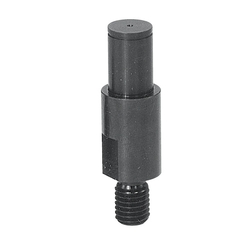 Cantilever Shafts / shouldered / external thread, ring groove / spanner flat
MISUMI Shipping Days: 3 Days
-
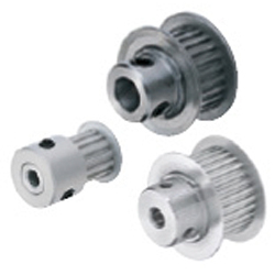 Timing belt pulleys / MXL / flanged pulley selectable / configurable / material selectable / treatment selectable
MISUMI Shipping Days: 6 Days
-
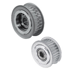 Tensioner Idlers / toothed / MXL, XL / flanged pulley selectable / single bearing, double bearing / aluminium
MISUMI Standard Price : 24.43 € Shipping Days: 6 Days


MISUMI Unit еxample related to this product


Tech Support
Payment Method


On-Demand Manufacturing
Certificates


Copyright © MISUMI Corporation All Rights Reserved.