
- inCAD Library Home
- > No.000109 Feeding Mechanism
No.000109 Feeding Mechanism
40
Stops and separates round bars in one step.
Related Category


Cam Followers
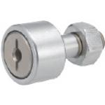
| Product name | Cam Followers/Flat Type/No Seal |
|---|---|
| Part number | CFFR5-13 |
Selection criteria
Suitable as a joint part of link mechanism.
Available sizes
■Cam Followers - Flat Type - No Seal
| Purpose | Main Body | Nut | |||
|---|---|---|---|---|---|
| Material | Seal | Material | Surface Treatment | ||
| N/A | Yes | ||||
| General | EN 1.3505 Equiv. | ○ | ○ | EN 1.1191 Equiv. | Black Oxide |
| EN 1.4125 Equiv. | ○ | ○ | EN 1.4301 Equiv. | - | |
| Low particle generation | - | ○ | |||
■Sizes and Dimensions.
| Stud Dia. | Thread Dia. x Pitch | Outer Ring Dia. | Outer race width | Overall Length |
|---|---|---|---|---|
| Ø5 | M5 x 0.8 | Ø13 | 9 | 23 |
| Ø6 | M6 x 1.0 | Ø16 | 11 | 28 |
| Ø8 | M8 x 1.25 | Ø19 | 11 | 32 |
| Ø10 | M10 x 1.25 | Ø22 | 12 | 36 |
| Ø26 | ||||
| Ø12 | M12 x 1.5 | Ø30 | 14 | 40 |
| Ø32 | ||||
| Ø16 | M16 x 1.5 | Ø35 | 18 | 52 |
| Ø18 | M18 x 1.5 | Ø40 | 20 | 58 |
| Ø20 | M20 x 1.5 | Ø52 | 22 | 66 |
Accuracy Info
■Cam follower accuracy
Stud Dia. Tolerance: h7
Outer ring Width Tolerance: 0/-0.12.
Outer ring DIA. Tolerance:
| Outer Ring Dia. | Tolerance |
|---|---|
| Ø13 | 0/-0.008 |
| Ø16 | |
| Ø19 | 0/-0.009 |
| Ø22 | |
| Ø26 | |
| Ø30 | |
| Ø32 | 0/-0.011 |
| Ø35 | |
| Ø40 | |
| Ø52 | 0/-0.013 |
Performance info
■Load capacity and rotation speed of cam follower
| Stud Dia. -Outer Ring Dia. | Basic Dynamic Load Rating C (kN) | Basic Static Load Rating Cor (kN) | Max. Allowable Load (kN) | Track Load Capacity (kN) | Rotational speed limit (rpm) | |
|---|---|---|---|---|---|---|
| With Seal | Without Seal | |||||
| Ø3-Ø10 | 1.47 | 1.18 | 0.36 | 1.37 | 32900 | 47000 |
| Ø4-Ø12 | 2.06 | 2.05 | 0.78 | 1.76 | 25900 | 37000 |
| Ø5-Ø13 | 3.14 | 2.77 | 1.42 | 2.25 | 20300 | 29000 |
| Ø6-Ø16 | 3.59 | 3.58 | 2.11 | 3.43 | 17500 | 25000 |
| Ø8-Ø19 | 4.17 | 4.65 | 4.73 | 4.02 | 14000 | 20000 |
| Ø10-Ø22 | 5.33 | 6.78 | 5.81 | 4.7 | 11900 | 17000 |
| Ø10-Ø26 | 5.49 | |||||
| Ø12-Ø30 | 7.87 | 9.79 | 9.37 | 7.06 | 9800 | 14000 |
| Ø12-Ø32 | 7.45 | |||||
| Ø16-Ø35 | 12 | 18.3 | 17.3 | 11.2 | 7000 | 10000 |
| Ø18-Ø40 | 14.7 | 25.2 | 26.1 | 14.4 | 5950 | 8500 |
| Ø20-Ø52 | 20.7 | 34.8 | 32.1 | 23.2 | 4900 | 7000 |

Shaft Collar
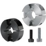
| Product name | Shaft Collars/With Counterbored Holes |
|---|---|
| Part number | PSCSG10-15 |
Selection criteria
Select the counterbored type to maintain the workability of the mounting screws when adjusting the position of shaft clamps.
Available sizes
■Shaft Collars - With Counterbored Holes
| Material | Surface Treatment |
|---|---|
| EN 1.1191 Equiv. | Black Oxide |
| Electroless Nickel Plating | |
| EN 1.4301 Equiv. | - |
■Sizes and Dimensions.
| Shaft Bore I.D. | Overall Thickness (width) | O.D. | Fastening Screw DIA. (Coarse) | For Screw Hole | |
|---|---|---|---|---|---|
| Pitch | Hole Dia. | ||||
| Ø6 | 8 | Ø24 | M3 | 15 | Ø3.5 |
| 10 | M4 | ||||
| Ø8 | 8 | Ø25 | M3 | 17 | |
| 10 | Ø28 | M4 | 18 | Ø4.5 | |
| Ø10 | Ø33 | 22 | Ø5.5 | ||
| 12 | M5 | ||||
| 15 | Ø36 | M6 | 23 | Ø6.6 | |
| Ø12 | 10 | Ø35 | M4 | 24 | Ø5.5 |
| 12 | M5 | ||||
| 15 | Ø38 | M6 | 25 | Ø6.6 | |
| Ø13 | 10 | Ø33 | M4 | 23 | Ø4.5 |
| 12 | Ø36 | M5 | 25 | Ø5.5 | |
| 15 | M6 | ||||
| Ø15 | 12 | Ø38 | M5 | 27 | |
| 15 | Ø40 | M6 | 28 | Ø6.6 | |
| Ø16 | 10 | Ø36 | M5 | 26 | Ø4.5 |
| 12 | Ø38 | 28 | Ø5.5 | ||
| 15 | Ø42 | M6 | 29 | Ø6.6 | |
| Ø20 | 12 | M5 | 32 | Ø5.5 | |
| 15 | Ø45 | M6 | 33 | Ø6.6 | |
| 20 | |||||
| Ø25 | 12 | Ø48 | M5 | 37 | Ø5.5 |
| 15 | Ø50 | M6 | 38 | Ø6.6 | |
| Ø30 | Ø55 | 43 | |||
| Ø35 | Ø60 | 48 | |||
| Ø40 | 18 | Ø78 | M8 | 60 | Ø9 |
| Ø50 | 22 | Ø88 | M10 | 71 | Ø11 |
Accuracy Info.
■Accuracy of shaft collars.
| I.D. Tolerance | +0.05/+0.01 |
|---|---|
| O.D. Tolerance | ±0.1 |
| Overall Thickness (width) Tolerance | ±0.1 |

Knuckle Joints
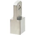
| Product name | Knuckle Joints/Tapped/Selectable |
|---|---|
| Part number | NJTB6-1.0-B4 |
| Features | Knuckle Joints equipped with Rotation Stopper and compatible with M3~M18 screws regardless of Convex Type or Concave Type. |
Selection criteria
Suitable as a oscillating part of cylinder link mechanism.
Available sizes
■Knuckle Joints - Tapped, Selectable
| Material | Surface Treatment | Convex Shaped | Concave Shaped |
|---|---|---|---|
| EN 1.1191 Equiv. | Black Oxide | ○ | ○ |
| Electroless Nickel Plating | - | ○ | |
| EN 1.4301 Equiv. | - | ○ | ○ |
■Sizes and Dimensions.
| Thread Dia. x Pitch | Joint Parts | Hole Dia. | Overall Length | Overall thickness | Width |
|---|---|---|---|---|---|
| Thickness (width) | |||||
| M3 x 0.5 | 4 ・ 5 | Ø4 | 20 | 10 | 10 |
| M4 x 0.7 | 5 ・ 6 | Ø5 | 25 | ||
| M5 x 0.8 | 12 | 12 | |||
| M6 x 1.0 | 4 ・ 6 | ||||
| M8 x 1.0 | 5 ・ 8 | Ø8 | 35 | 16 | 16 |
| M8 x 1.25 | |||||
| M10 x 1.25 | 6 ・ 10 | Ø10 | 20 | 20 | |
| M10 x 1.5 | |||||
| M12 x 1.25 | 8 ・ 10 | Ø12 | 40 | 22 | 22 |
| M12 x 1.5 | |||||
| M14 x 1.5 | 10 ・ 12 | 50 | 25 | 25 | |
| M16 x 1.5 | 55 | ||||
| M18 x 1.5 | 12 ・ 14 | 28 | 28 |

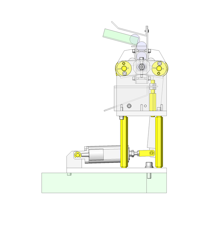
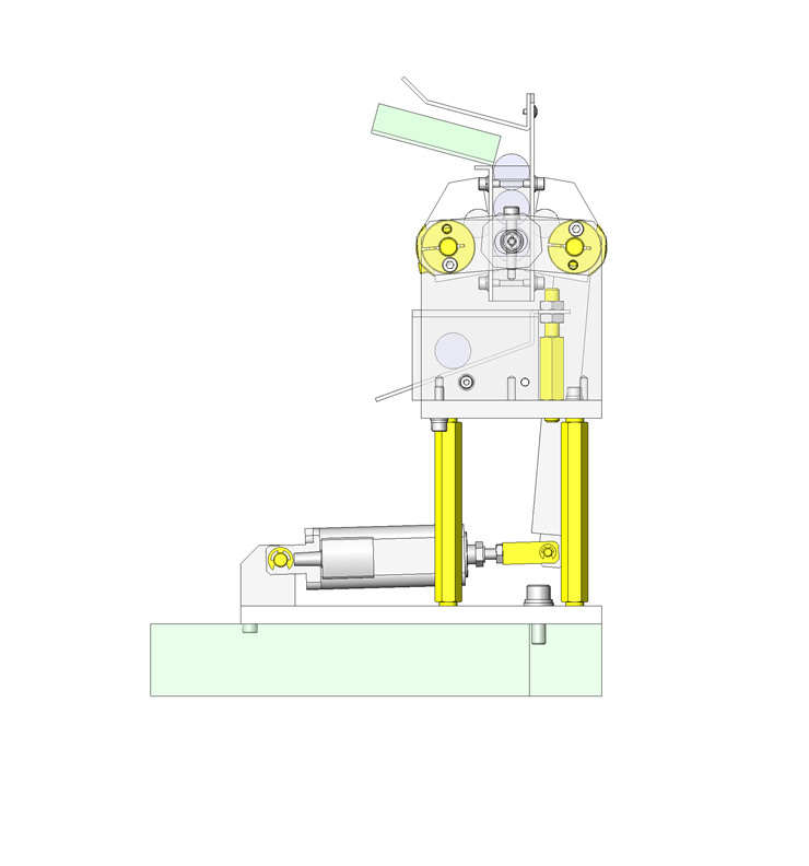
IDEA NOTE Separates cylindrical workpieces by means of a single actuator.
By setting the claw rotation center positions, claw opening amount and stopper position with ingenuity, separation action by a single actuator is made possible.
The claws rotate to release the lowermost workpiece and stop the next workpiece.


-

-
 Terms of use of CAD data and simplified drawing data
- These terms and conditions (hereinafter referred to as “the Terms") set forth the conditions for downloading CAD data and simplified drawing data provided by MISUMI Corporation (hereinafter referred to as "MISUMI") via www.misumi-europe.com operated by MISUMI Europa GmbH(hereinafter referred to as the "Website"). By downloading CAD data and simplified drawing data posted on the Website (hereafter referred to as “Data”), customers are deemed to have agreed to these Terms.
- 1. Purpose of Use
-
MISUMI offers the following:
1)CAD data found on the Website (3D CAD data, 3D Intermediate data and 2D CAD data) for the purpose of informing customers of the characteristics of the products offered by MISUMI or a manufacturer affiliated with MISUMI for use in their designs.
2)Simplified drawing data (in PDF format) for the purpose of checking the specifications of products. - 2. Characteristics of Data
- There may be a discrepancy in certain characteristics of products (for example: tolerance, surface roughness, chamfer, etc.) between the Data and the actual product. Furthermore, for the purpose of reducing the file size of the Data, some information such as oil groove shapes, threads, or spring shapes, may be removed from the Data.
- 3. Disclaimer
- MISUMI carefully creates the Data but makes no warranty as to the quality, accuracy, functionality, safety, reliability, etc., of the Data. MISUMI may at any time, and with no prior notice to customers, revise or delete Data. MISUMI assumes no responsibility for any damage or loss resulting from any revision or deletion of the Data, or any errors in said data. Customers are solely responsible for all aspects of their own designs, including those made using the Data. MISUMI may provide customers with design example data on the Website, but the quality, accuracy, functionality, safety, reliability, etc., of such data are not guaranteed. MISUMI may, at any time, and in its sole discretion, request that the customer cease its use of or destroy the Data in its possession. MISUMI may request the customer provide MISUMI documentation of such destruction.
- 4.Prohibited Acts
-
Customers or users of the Data, are prohibited from the following acts regarding the Data, in whole or in part:
(1)Requesting quotations or placing orders for products with third parties other than those authorized by MISUMI or its affiliates;
(2)Receiving quotations or orders for products from third parties by providing the Data to a third party or using the Data in their own business;
(3)Displaying links to the Website related to the Data on their own websites, etc., without consent of MISUMI or its affiliates;
(4)Using or reproducing the Data beyond the scope of the above-stated Purpose of Use;
(5)Modifying, altering, tampering with, translating, or adapting the Data;
(6)Selling, transferring, lending, sublicensing, or providing the Data to third parties in any way without consent of MISUMI or its affiliates;
(7)Altering the content, reverse engineering, decompiling, disassembling, or analyzing the Data;
(8)Publicly disclosing or exhibiting the Data without consent of MISUMI or its affiliates;
(9)Using the Data for the purpose of providing products and services identical or similar to those of MISUMI or its affiliates;
(10)Performing acts that interfere with the proper functioning of this Website, such as acquiring Data in bulk. - 5. Copyright
-
All title and copyright in and to any information contained in the Data are owned by MISUMI or the relevant manufacturer affiliated with MISUMI and are protected by applicable copyright laws and international treaties. By downloading Data, the customer acquires no ownership rights of any kind in the intellectual property contained within. Without prior approval from MISUMI, no part of the Data may be utilized (reproduced, modified, reverse-engineered, uploaded, presented, sent, distributed, licensed, sold, or published) for any purpose other than that mentioned above.
In the event Data is found to have been to be used for any purpose other than that mentioned above or against any applicable laws or the Terms, MISUMI may pursue any legal remedy available to it, which may result in forbidding the offending user from using the Data or accessing the Website. - 6. Third-Party Data
- MISUMI offers some Data provided by third parties. Such Data may be subject to separate terms and conditions, in addition to these terms. MISUMI makes no guarantee or warranty regarding Data from third parties.
- 7. Export Control
- Customers shall comply with all applicable laws and regulations regarding the export of the Data.
- 8. Amendments to the Terms
- MISUMI may, at any time, and in its sole discretion, modify these terms and conditions; any such modification will be effective immediately.
- 9. Severability
- If any term or provision of these Terms is invalid, illegal, or unenforceable in any jurisdiction, such invalidity, illegality, or unenforceability shall not affect any other term or provision of these Terms or invalidate or render unenforceable such term or provision in any other jurisdiction. Section 139 BGB (German Civil Code) shall not apply.
- 10.Miscellaneous
-
In the event that Customers violate the Terms, MISUMI and/or MISUMI Europa GmbH shall be entitled to claim the damages and expenses (including attorney's fees) incurred by such violation against the Customers.
These Terms and any disputes arising in connection therewith shall be exclusively governed by and construed in accordance with the laws of the Federal Republic of Germany, without regard to its conflicts of law principles. The courts located in Frankfurt am Main/Germany shall have exclusive jurisdiction to adjudicate any dispute arising in connection with these Terms. By downloading the Data, you agree to submit to the exclusive and personal jurisdiction of the courts located in Frankfurt am Main/Germany. - Revised: September 21, 2025
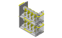
CAD Data Download (Unit Assembly)
CAD Data Download: File Format
Cautions on the CAD data
-
Assembly data shows the assembly drawings in the concept design phase. The sole purpose of the data is to explain the structure and functionality of the assembly and is not considered nor to be used as a final design.
You will need to edit the Data so that it meets your specific design conditions. -
The CAD data unit assembly consists of sub-assemblies.
Each sub-assembly unit can be used as it is or can be edited. - The Data for fabricated parts is based on easy-to-edit dimensions and shapes in sketches and histories.
- The Data including the third-part components are made by the Company.
* The part in the frame is a sub-assembly unit.
-

- * Unit assembly CAD data consists of some sub-assemblies.
Each sub-assembly unit can be used as it is or can be edited.
Application Overview
Purpose
- Purpose
- To separate and transfer cylindrical workpieces.
- Operation
- The electric actuator is used to operate the arm and claws, which separate the workpieces one by one.
Target workpiece
- Aluminum roller.
- Size: Ø20 x L200mm.
- Weight: 170g.
Design Specifications
Operating Conditions or Design Requirements
- Claw rotation angle: 10°
- Cylinder stroke: 30mm.
Selection Criteria for Main Components
- An electric cylinder with a 30mm stroke is selected to rotate the claws by 10 degrees.
Design Evaluation
Verification of main components
- Verify whether the robot cylinder has a speed high enough to make the cam perform workpiece separation.
- Confirmation of robot cylinder speed.
- Conditional value: gravitational acceleration g = 9.8N/m², stroke of robot cylinder that rotates cam at rotation angle of 10°: L0 = 29.6mm,
Equation of free-fall motion (when initial velocity is Vo = 0, t = elapsed time [sec], h = displacement amount [m]), velocity: V = G x t, displacement amount: h = 1/2 x t², elapsed time: t = √(2 x h/g)
State (1): The lower part of cam is closed and the lowermost workpiece is stopped.
State (2): The lower part of cam is opened and the lowermost workpiece and the next workpiece start dropping.
State (3): The lower part of the cam is completely opened and the next workpiece is stopped by the stopper.
Displacement amount of next workpiece between state (2) and state (3): h = 4.4mm = 0.0044m,
Stroke of robot cylinder that rotates cam at rotation angle of 0.8° between state (2) and state (3): L1 = 2.37mm,
Elapsed time during this period: t = √(2 x h/g) = √(2 x 0.0044/9.8) = 0.03 sec
Required cylinder speed calculated from robot cylinder stroke and elapsed time: Vs = L1/t = 2.37/0.03 = 79mm/sec
As this speed is within the robot cylinder maximum speed of 100 mm/sec, the next workpiece is stopped and workpiece separation is possible.
- Conditional value: gravitational acceleration g = 9.8N/m², stroke of robot cylinder that rotates cam at rotation angle of 10°: L0 = 29.6mm,
Other Design Consideration
- Due to the lack of an air pressure source, an electric cylinder is used.
- The height of the shoot is designed to be adjusted using the external threads of hex posts and nuts.
Explore Similar Application Examples


Payment Method


On-Demand Manufacturing
Certificates


Copyright © MISUMI Corporation All Rights Reserved.