
- inCAD Library Home
- > No.000239 W reversing mechanism
No.000239 W reversing mechanism
58
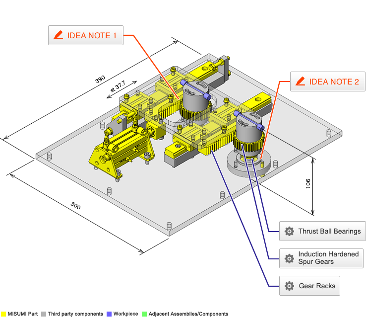
Angled rack and pinion mechanism used to reverse a workpiece.
Related Category


Gear Racks
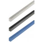
| Product name | Gear Racks/Pressure Angle 20Deg./Configurable L Dimension |
|---|---|
| Part number | RGEAL1.5ST-100-A5-B45-C45 |
| Features | This enables to switch between rotating motion and linear motion. Length and mounting hole machining can be specified. |
Selection criteria
Selected to achieve simultaneous rotation.
Risk info.
Wear due to lack of teeth surface hardening.
Available sizes
■Rack Gears (One End Machined)
| Material | Surface Treatment |
|---|---|
| EN 1.1191 Equiv. | Black Oxide |
| Free-Cutting Brass Bar | - |
| EN 1.4301 Equiv. | - |
| MC Nylon | - |
■Sizes and Dimensions
| Material | Module | Tooth width | Overall Length 1mm Increments |
|---|---|---|---|
| EN 1.1191 Equiv. | 1.0 | 10 | 20-400 |
| 1.5 | 15 | ||
| 2.0 | 20 | ||
| 2.5 | 25 | ||
| 3.0 | 30 | ||
| Free-Cutting Brass Bar | 0.5 | 3 | 20-280 |
| 0.8 | 4 | ||
| EN 1.4301 Equiv. | 0.5 | 3 | 20-280 |
| 0.8 | 4 | ||
| 1.0 | 10 | 20-480 | |
| 1.5 | 15 | ||
| 2.0 | 20 | ||
| 2.5 | 25 | ||
| 3.0 | 30 | ||
| MC Nylon | 0.5 | 3 | 20-280 |
| 0.8 | 4 | ||
| 1.0 | 10 | 20-480 |
Accuracy Info
■Rack Gear (Accuracy Information)
Accuracy: Accumulated Pitch Error (µm)
| Module | Overall Length | ||||
|---|---|---|---|---|---|
| 100. or Less | 101-300 | 301-500 | 501-1000 | 1001-1980 | |
| 0.5-1.5 | 54(76) | 65(92) | 72(101) | 100(117) | 99(139) |
| 2.0-3.0 | 62(86) | 73(102) | 80(112) | 91(128) | 105(148) |

Induction Hardened Spur Gears
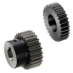
| Product name | Spur Gears/Induction Hardened/Pressure Angle 20Deg. |
|---|---|
| Part number | GEAHBH1.5-32-15-A-20 |
| Features | Gears with hardened teeth which provides excellent strength, abrasion resistance and high precision |
Selection criteria
Reduce wear to gear teeth.
Available sizes
■Induction Hardened Spur Gears (Ground)
| Material | Surface Treatment | Hardness | Accessory |
|---|---|---|---|
| EN 1.1191 Equiv. | Black Oxide Coating | Tooth Induction Hardened 51 - 55 HRC (Depth 1mm or more) | Set screw (EN 1.7220 Equiv. Black Oxide Coating) |
■Sizes and Dimensions
| Module | Number of Teeth | Shaft Bore DIA. (1mm increment) | |
|---|---|---|---|
| Round Hole, Round Hole + Tap | Keyway, Keyway + Tap | ||
| 1.0 | 18 | 6-10 | - |
| 20 | 6-11 | 8 ・ 10 | |
| 22 | 8-14 | 8-12 | |
| 24 | |||
| 25 | |||
| 26 | |||
| 28 | |||
| 30 | 10-17 | 10-15 | |
| 32 | |||
| 35 | |||
| 36 | |||
| 40 | 10-21 | 10-18 | |
| 45 | |||
| 48 | |||
| 50 | 12-24 | 12-18 | |
| 60 | 12-28 | 12-25 | |
| 70 | |||
| 80 | 15-35 | 15-30 | |
| 100 | |||
| 1.5 | 15 | 10-12 | 10 |
| 16 | 10-13 | 10 ・ 11 | |
| 18 | 10-15 | 10-13 | |
| 20 | 10-16 | 10-14 | |
| 24 | 12-19 | 12-17 | |
| 25 | 12-21 | 12-18 | |
| 26 | 12-22 | 12-19 | |
| 28 | 15-25 | 15-19 | |
| 30 | 15-26 | 15-23 | |
| 32 | 15-28 | 15-24 | |
| 35 | 15-29 | 15-26 | |
| 36 | 15-31 | 15-28 | |
| 40 | 15-35 | 15-31 | |
| 45 | 18-35 | 18-31 | |
| 48 | |||
| 50 | 18-42 | 18-38 | |
| 60 | 20-42 | 20-38 | |
| 70 | |||
| Gear specification | Shaft Bore Specs. | |||
|---|---|---|---|---|
| Round Hole | Round Hole + Tap | Keyway | Keyway + Tap | |
| No hub | ○ | ○ | ||
| With Hub | ○ | ○ | ○ | |
Accuracy Info
■Accuracy of Spur Gear.
Gear accuracy: Previous JIS B 1702 4 Class (New JIS B 1702-1 - 8 class equivalent).
Shaft Bore Dia. Tolerance: H7.

Thrust Ball Bearings
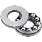
| Product name | Thrust Ball Bearings |
|---|---|
| Part number | B51102 |
Selection criteria
Selected for supporting thrust load of workpiece and components.
Available sizes
■Thrust Ball Bearing
| Material | |
|---|---|
| Steel Type | EN 1.3505 Equiv. |
| Stainless Steel Type | EN 1.4125 Equiv. |
■Sizes and Dimensions
| I.D. | Track Plate O.D. | Track Plate I.D. | Thickness |
|---|---|---|---|
| 10 | 24 | 11 | 9 |
| 26 | 12 | 11 | |
| 12 | 26 | 13 | 9 |
| 28 | 14 | 11 | |
| 15 | 28 | 16 | 9 |
| 32 | 17 | 12 | |
| 17 | 30 | 18 | 9 |
| 35 | 19 | 12 | |
| 20 | 35 | 21 | 10 |
| 40 | 22 | 14 | |
| 25 | 42 | 26 | 11 |
| 47 | 27 | 15 | |
| 30 | 32 | 11 | |
| 52 | 32 | 16 |
Performance info.
■Load information of the thrust ball bearings
| I.D. | Track Plate O.D. | Basic Load Rating | Allowable Rotational Speed rpm | |||
|---|---|---|---|---|---|---|
| Steel Type | Stainless Steel Type | |||||
| Ca (Dynamic) kN | Coa (Static) kN | Ca (Dynamic) kN | Coa (Static) kN | |||
| 10 | 24 | 10.1 | 14 | 5 | 6.96 | 6700 |
| 26 | 12.8 | 17.1 | - | - | 6000 | |
| 12 | 26 | 10.4 | 15.4 | 5.15 | 7.7 | 6700 |
| 28 | 13.3 | 19 | - | - | 5600 | |
| 15 | 28 | 10.6 | 16.8 | 5.25 | 8.38 | 6300 |
| 32 | 16.7 | 24.8 | - | - | 5000 | |
| 17 | 30 | 11.4 | 19.5 | 5.39 | 9.07 | 6000 |
| 35 | 17.3 | 27.3 | - | - | 4800 | |
| 20 | 35 | 15.1 | 26.6 | 7.11 | 12.36 | 5300 |
| 40 | 22.5 | 37.5 | - | - | 4300 | |
| 25 | 42 | 19.7 | 37 | 9.76 | 18.63 | 4800 |
| 47 | 28 | 50.5 | - | - | 3800 | |
| 30 | 20.6 | 42 | 10.2 | 21.08 | 4300 | |
| 52 | 29.5 | 58 | - | - | 3400 | |


IDEA NOTE Radial + thrust
Workpiece positioning and rotation are supported by a mechanism combining a radial bearing and a thrust bearing.


-

-
 Terms of use of CAD data and simplified drawing data
- These terms and conditions (hereinafter referred to as “the Terms") set forth the conditions for downloading CAD data and simplified drawing data provided by MISUMI Corporation (hereinafter referred to as "MISUMI") via www.misumi-europe.com operated by MISUMI Europa GmbH(hereinafter referred to as the "Website"). By downloading CAD data and simplified drawing data posted on the Website (hereafter referred to as “Data”), customers are deemed to have agreed to these Terms.
- 1. Purpose of Use
-
MISUMI offers the following:
1)CAD data found on the Website (3D CAD data, 3D Intermediate data and 2D CAD data) for the purpose of informing customers of the characteristics of the products offered by MISUMI or a manufacturer affiliated with MISUMI for use in their designs.
2)Simplified drawing data (in PDF format) for the purpose of checking the specifications of products. - 2. Characteristics of Data
- There may be a discrepancy in certain characteristics of products (for example: tolerance, surface roughness, chamfer, etc.) between the Data and the actual product. Furthermore, for the purpose of reducing the file size of the Data, some information such as oil groove shapes, threads, or spring shapes, may be removed from the Data.
- 3. Disclaimer
- MISUMI carefully creates the Data but makes no warranty as to the quality, accuracy, functionality, safety, reliability, etc., of the Data. MISUMI may at any time, and with no prior notice to customers, revise or delete Data. MISUMI assumes no responsibility for any damage or loss resulting from any revision or deletion of the Data, or any errors in said data. Customers are solely responsible for all aspects of their own designs, including those made using the Data. MISUMI may provide customers with design example data on the Website, but the quality, accuracy, functionality, safety, reliability, etc., of such data are not guaranteed. MISUMI may, at any time, and in its sole discretion, request that the customer cease its use of or destroy the Data in its possession. MISUMI may request the customer provide MISUMI documentation of such destruction.
- 4.Prohibited Acts
-
Customers or users of the Data, are prohibited from the following acts regarding the Data, in whole or in part:
(1)Requesting quotations or placing orders for products with third parties other than those authorized by MISUMI or its affiliates;
(2)Receiving quotations or orders for products from third parties by providing the Data to a third party or using the Data in their own business;
(3)Displaying links to the Website related to the Data on their own websites, etc., without consent of MISUMI or its affiliates;
(4)Using or reproducing the Data beyond the scope of the above-stated Purpose of Use;
(5)Modifying, altering, tampering with, translating, or adapting the Data;
(6)Selling, transferring, lending, sublicensing, or providing the Data to third parties in any way without consent of MISUMI or its affiliates;
(7)Altering the content, reverse engineering, decompiling, disassembling, or analyzing the Data;
(8)Publicly disclosing or exhibiting the Data without consent of MISUMI or its affiliates;
(9)Using the Data for the purpose of providing products and services identical or similar to those of MISUMI or its affiliates;
(10)Performing acts that interfere with the proper functioning of this Website, such as acquiring Data in bulk. - 5. Copyright
-
All title and copyright in and to any information contained in the Data are owned by MISUMI or the relevant manufacturer affiliated with MISUMI and are protected by applicable copyright laws and international treaties. By downloading Data, the customer acquires no ownership rights of any kind in the intellectual property contained within. Without prior approval from MISUMI, no part of the Data may be utilized (reproduced, modified, reverse-engineered, uploaded, presented, sent, distributed, licensed, sold, or published) for any purpose other than that mentioned above.
In the event Data is found to have been to be used for any purpose other than that mentioned above or against any applicable laws or the Terms, MISUMI may pursue any legal remedy available to it, which may result in forbidding the offending user from using the Data or accessing the Website. - 6. Third-Party Data
- MISUMI offers some Data provided by third parties. Such Data may be subject to separate terms and conditions, in addition to these terms. MISUMI makes no guarantee or warranty regarding Data from third parties.
- 7. Export Control
- Customers shall comply with all applicable laws and regulations regarding the export of the Data.
- 8. Amendments to the Terms
- MISUMI may, at any time, and in its sole discretion, modify these terms and conditions; any such modification will be effective immediately.
- 9. Severability
- If any term or provision of these Terms is invalid, illegal, or unenforceable in any jurisdiction, such invalidity, illegality, or unenforceability shall not affect any other term or provision of these Terms or invalidate or render unenforceable such term or provision in any other jurisdiction. Section 139 BGB (German Civil Code) shall not apply.
- 10.Miscellaneous
-
In the event that Customers violate the Terms, MISUMI and/or MISUMI Europa GmbH shall be entitled to claim the damages and expenses (including attorney's fees) incurred by such violation against the Customers.
These Terms and any disputes arising in connection therewith shall be exclusively governed by and construed in accordance with the laws of the Federal Republic of Germany, without regard to its conflicts of law principles. The courts located in Frankfurt am Main/Germany shall have exclusive jurisdiction to adjudicate any dispute arising in connection with these Terms. By downloading the Data, you agree to submit to the exclusive and personal jurisdiction of the courts located in Frankfurt am Main/Germany. - Revised: September 21, 2025
CAD Data Download (Unit Assembly)
CAD Data Download: File Format
Cautions on the CAD data
-
Assembly data shows the assembly drawings in the concept design phase. The sole purpose of the data is to explain the structure and functionality of the assembly and is not considered nor to be used as a final design.
You will need to edit the Data so that it meets your specific design conditions. -
The CAD data unit assembly consists of sub-assemblies.
Each sub-assembly unit can be used as it is or can be edited. - The Data for fabricated parts is based on easy-to-edit dimensions and shapes in sketches and histories.
- The Data including the third-part components are made by the Company.
* The part in the frame is a sub-assembly unit.
-

- * Unit assembly CAD data consists of some sub-assemblies.
Each sub-assembly unit can be used as it is or can be edited.
Application Overview
Purpose
- One axis of the linear rack section is driven by a cylinder, the pinions on the other axis are then rotated simultaneously to reverse them to any desired angle. (90° in the example).
Points for use
- The workpiece is transferred in and out by the up and down motion of the chucking mechanism on the external unit.
- The stroke is controlled by both the sensor of the cylinder, and a mechanical stopper to ensure the precise workpiece angle.
Target workpiece
- Material: Resin
- External Shape:Ø9 x W41mm
- Mass: 3g
Features
Operating specifications ・ Dimensions
- Workpiece rotation angle: 90°
- Pinion Gear: m1.5, z32, P.C.D. 48mm
- Required Cylinder Stroke: 37.7mm
- System External Shape: W 390 x D 300 x H 106mm
Required accuracy ・ Load
- Cylinder Thrust: 6.83N or more
Selection criteria of main components
- Cylinder
- Adopted thin type cylinder for space saving.
- Pinion Gear
- A pinion gear with a tap hole is used affixed to workpiece jig, so the jig can be rotated.
Design point
Calculation processes for the main components
- Whether the cylinder thrust force can handle the slide-way load and rotation section load is verified below.
- Thrust of cylinder (Ø20mm, ST 50mm)
- Condition value: Slide way total weight m1 = 1.714kg, linear guide friction coefficient μ1 = 0.005 (from catalog), rotating section total weight m2 = 0.688kg, conversion factor to slide motion of rotating section μ2 = 1 (assumed as a slide with a friction coefficient of 1 for safe side), operating pressure of cylinder: 0.2MPa
- Slide way load: F1 = m1 x g x μ1, thus, F1 = 1.714 x 9.8 x 0.005 = 0.084N
- Rotating section load: F2 = m2 x g x μ2, thus, F2 = 0.688 x 9.8 x 1 = 6.742N
- Total load: F = F1 + F2 = 0.084 + 6.742 = 6.83N
- Pull side thrust of cylinder: F0 = 47N(from catalog)
- Safety factor: F0/F = 47/6.83 ≈ 6.88
Structure elaboration and design key points.
- This system is effective for a corner section, that requires the reversing of multiple parts on an automated line in single file.
- The workpiece table has a slotted hole in the rotated direction in order to enable the adjustment of the workpiece position during rotation.
- Installing a sensor and mechanical stopper in parallel enables precise positioning and angle adjustment of the workpiece. It also reduces the generation of moments by stopping the transmission of cylinder thrust prior to hitting the mechanical stopper.
Explore Similar Application Examples


Payment Method


On-Demand Manufacturing
Certificates


Copyright © MISUMI Corporation All Rights Reserved.