
- inCAD Library Home
- > No.000108 Linear Movement Mechanism
No.000108 Linear Movement Mechanism
46
46
Slowly strokes for a short distance.
Related Category


Couplings
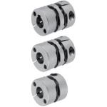
| Product name | Couplings/High Torque Disc/Clamping |
|---|---|
| Part number | MCKLCLK32-10-12 |
* Orange colored cells in the table below indicate the part numbers used in this example.
Selection criteria
Effective for transmissions with large allowable values of lateral / angular misalignments
Available sizes
■Disc Couplings - High Torque, Clamping (Double Disc)
| Material | Surface Treatment | Accessory | Keywayed shaft bore | |
|---|---|---|---|---|
| Main Body | Disc | Main Body | ||
| Aluminum Diecast | Carbon Fiber | Electroless Nickel Plating | Hex Socket Head Cap Screw | None ・ One side ・ Both sides |
■Sizes and Dimensions
| O.D. | Shaft bore DIA. (Select drive/driven sides) | Overall Length | Clamp Screw | |||||||||||||||||
|---|---|---|---|---|---|---|---|---|---|---|---|---|---|---|---|---|---|---|---|---|
| Ø3 | Ø4 | Ø5 | Ø6 | Ø6.35 | Ø7 | Ø8 | Ø9.53 | Ø10 | Ø11 | Ø12 | Ø14 | Ø15 | Ø16 | Ø18 | Ø20 | Ø22 | Ø24 | |||
| Ø13 | ○ | ○ | ○ | 19 | M2 | |||||||||||||||
| Ø16 | ○ | ○ | ○ | 23.2 | M2.5 | |||||||||||||||
| Ø20 | ○ | ○ | ○ | ○ | ○ | ○ | 26 | |||||||||||||
| Ø25 | ○ | ○ | ○ | ○ | ○ | ○ | ○ | 30.2 | M3 | |||||||||||
| Ø32 | ○ | ○ | ○ | ○ | ○ | ○ | 41 | M4 | ||||||||||||
| Ø40 | ○ | ○ | ○ | ○ | ○ | ○ | ○ | ○ | ○ | 47 | M5 | |||||||||
| Ø50 | ○ | ○ | ○ | ○ | ○ | ○ | ○ | 53 | M6 | |||||||||||
* Keywayed bore type is selectable for Ø6 or larger
Accuracy Info
■Accuracy of coupling
| O.D. | Shaft Bore Tolerance | Allowable Angular Misalignment (°) | Lateral Misalignment (mm) |
|---|---|---|---|
| Ø13 | H8 | 2.5 | 0.2 |
| Ø16 | |||
| Ø20 | |||
| Ø25 | |||
| Ø32 | |||
| Ø40 | 0.3 | ||
| Ø50 |
Performance info.
■Load info. on coupling
| O.D. | Allowable Torque (N・m) | Max. Rotational Speed (r/min) | Moment of Inertia (kg・m²) |
|---|---|---|---|
| Ø13 | 0.35 | 12000 | 8.0 x 10⁻⁸ |
| Ø16 | 0.6 | 9000 | 2.4 x 10⁻⁷ |
| Ø20 | 0.9 | 7600 | 7.2 x 10⁻⁷ |
| Ø25 | 2.2 | 6000 | 2.2 x 10⁻⁶ |
| Ø32 | 3.8 | 4800 | 6.0 x 10⁻⁶ |
| Ø40 | 6.8 | 4000 | 1.7 x 10⁻⁵ |
| Ø50 | 11.0 | 3500 | 4.6 x 10⁻⁵ |

Ball Roller Units
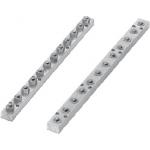
| Product name | Ball Roller Units/Hex Head/Stud/Press-Fit Type |
|---|---|
| Part number | BUHA400 |
* Orange colored cells in the table below indicate the part numbers used in this example.
Selection criteria
Effective rolling materials to move the workpiece freely in the XY direction
Available sizes
■Ball Roller Units - Press Fit Type
| Material | Ball Roller | |||
|---|---|---|---|---|
| Ball Rollers | Frame | Load capacity per pc | ||
| Main Body / Spacer | Main Ball / Sub Ball | |||
| EN 1.4301 Equiv. | EN 1.4125 Equiv.(HRC55 ~ ) | EN AW-6063 Equiv.(Clear Anodize) | BCHA24 | 343N |
■Ball Roller Units - Press Fit Type
| Overall Length | Number of Rollers | Roller Pitch | Overall Width | Overall Height |
|---|---|---|---|---|
| 200 | 4 | 50 | 40 | 32 |
| 400 | 8 | |||
| 600 | 12 |


-
 Terms of use of CAD data and simplified drawing data
- These terms and conditions (hereinafter referred to as “the Terms") set forth the conditions for downloading CAD data and simplified drawing data provided by MISUMI Corporation (hereinafter referred to as "MISUMI") via www.misumi-europe.com operated by MISUMI Europa GmbH(hereinafter referred to as the "Website"). By downloading CAD data and simplified drawing data posted on the Website (hereafter referred to as “Data”), customers are deemed to have agreed to these Terms.
- 1. Purpose of Use
-
MISUMI offers the following:
1)CAD data found on the Website (3D CAD data, 3D Intermediate data and 2D CAD data) for the purpose of informing customers of the characteristics of the products offered by MISUMI or a manufacturer affiliated with MISUMI for use in their designs.
2)Simplified drawing data (in PDF format) for the purpose of checking the specifications of products. - 2. Characteristics of Data
- There may be a discrepancy in certain characteristics of products (for example: tolerance, surface roughness, chamfer, etc.) between the Data and the actual product. Furthermore, for the purpose of reducing the file size of the Data, some information such as oil groove shapes, threads, or spring shapes, may be removed from the Data.
- 3. Disclaimer
- MISUMI carefully creates the Data but makes no warranty as to the quality, accuracy, functionality, safety, reliability, etc., of the Data. MISUMI may at any time, and with no prior notice to customers, revise or delete Data. MISUMI assumes no responsibility for any damage or loss resulting from any revision or deletion of the Data, or any errors in said data. Customers are solely responsible for all aspects of their own designs, including those made using the Data. MISUMI may provide customers with design example data on the Website, but the quality, accuracy, functionality, safety, reliability, etc., of such data are not guaranteed. MISUMI may, at any time, and in its sole discretion, request that the customer cease its use of or destroy the Data in its possession. MISUMI may request the customer provide MISUMI documentation of such destruction.
- 4.Prohibited Acts
-
Customers or users of the Data, are prohibited from the following acts regarding the Data, in whole or in part:
(1)Requesting quotations or placing orders for products with third parties other than those authorized by MISUMI or its affiliates;
(2)Receiving quotations or orders for products from third parties by providing the Data to a third party or using the Data in their own business;
(3)Displaying links to the Website related to the Data on their own websites, etc., without consent of MISUMI or its affiliates;
(4)Using or reproducing the Data beyond the scope of the above-stated Purpose of Use;
(5)Modifying, altering, tampering with, translating, or adapting the Data;
(6)Selling, transferring, lending, sublicensing, or providing the Data to third parties in any way without consent of MISUMI or its affiliates;
(7)Altering the content, reverse engineering, decompiling, disassembling, or analyzing the Data;
(8)Publicly disclosing or exhibiting the Data without consent of MISUMI or its affiliates;
(9)Using the Data for the purpose of providing products and services identical or similar to those of MISUMI or its affiliates;
(10)Performing acts that interfere with the proper functioning of this Website, such as acquiring Data in bulk. - 5. Copyright
-
All title and copyright in and to any information contained in the Data are owned by MISUMI or the relevant manufacturer affiliated with MISUMI and are protected by applicable copyright laws and international treaties. By downloading Data, the customer acquires no ownership rights of any kind in the intellectual property contained within. Without prior approval from MISUMI, no part of the Data may be utilized (reproduced, modified, reverse-engineered, uploaded, presented, sent, distributed, licensed, sold, or published) for any purpose other than that mentioned above.
In the event Data is found to have been to be used for any purpose other than that mentioned above or against any applicable laws or the Terms, MISUMI may pursue any legal remedy available to it, which may result in forbidding the offending user from using the Data or accessing the Website. - 6. Third-Party Data
- MISUMI offers some Data provided by third parties. Such Data may be subject to separate terms and conditions, in addition to these terms. MISUMI makes no guarantee or warranty regarding Data from third parties.
- 7. Export Control
- Customers shall comply with all applicable laws and regulations regarding the export of the Data.
- 8. Amendments to the Terms
- MISUMI may, at any time, and in its sole discretion, modify these terms and conditions; any such modification will be effective immediately.
- 9. Severability
- If any term or provision of these Terms is invalid, illegal, or unenforceable in any jurisdiction, such invalidity, illegality, or unenforceability shall not affect any other term or provision of these Terms or invalidate or render unenforceable such term or provision in any other jurisdiction. Section 139 BGB (German Civil Code) shall not apply.
- 10.Miscellaneous
-
In the event that Customers violate the Terms, MISUMI and/or MISUMI Europa GmbH shall be entitled to claim the damages and expenses (including attorney's fees) incurred by such violation against the Customers.
These Terms and any disputes arising in connection therewith shall be exclusively governed by and construed in accordance with the laws of the Federal Republic of Germany, without regard to its conflicts of law principles. The courts located in Frankfurt am Main/Germany shall have exclusive jurisdiction to adjudicate any dispute arising in connection with these Terms. By downloading the Data, you agree to submit to the exclusive and personal jurisdiction of the courts located in Frankfurt am Main/Germany. - Revised: September 21, 2025
CAD Data Download (Unit Assembly)
CAD Data Download: File Format
Cautions on the CAD data
-
Assembly data shows the assembly drawings in the concept design phase. The sole purpose of the data is to explain the structure and functionality of the assembly and is not considered nor to be used as a final design.
You will need to edit the Data so that it meets your specific design conditions. -
The CAD data unit assembly consists of sub-assemblies.
Each sub-assembly unit can be used as it is or can be edited. - The Data for fabricated parts is based on easy-to-edit dimensions and shapes in sketches and histories.
- The Data including the third-part components are made by the Company.
* The part in the frame is a sub-assembly unit.
-

- * Unit assembly CAD data consists of some sub-assemblies.
Each sub-assembly unit can be used as it is or can be edited.
Application Overview
Purpose
- Purpose
- Jack for switching mold type.
- Operation
- Rotary movement is converted into linear movement. By rotating the rotary actuator by 180°, the lead screw is rotated. The nut on the lead screw makes linear movements to move up and down.
Points for use
- A heavy load is slowly raised a short distance. A rotary actuator is used as the drive source.
Target workpiece
- Mold for lead frame
- Size: W180 x D310 x H214mm
- Weight: 34kg
Design Specifications
Operating Conditions or Design Requirements
- Ascending/descending stroke: 2.5mm
- Safety factor: S = 1.7
- Outer dimensions: W180 x D400 x H262mm
Required Performance
- Positioning accuracy: ±0.05mm
- Upward thrust: 580N
Selection Criteria for Main Components
- Lead Screw
- As the ascending/descending stroke is 2.5 mm, a 5-mm lead is selected as its multiple number lead.
- Rotary actuator
- A rotary actuator with an oscillation angle of 180° and a torque of 1.7 [N・m] (0.5 MPa) or higher is selected.
Design Evaluation
Verification of main components
- Whether an appropriate thrust for raising the workpiece can be obtained is verified based on the specifications of the rotary actuator and the lead screw.
- Calculation of upward thrust
- Conditional value: workpiece mass W = 55kg, gravitational acceleration g = 9.8m/s², friction coefficient μ = 0.21, lead of lead screw R = 5mm, lead angle d = 4°40' = 4.67°, rotary actuator torque T = 1.863N・m = 186.3N・cm
Screw efficiency: η = (1 - μ x tan(d))/(1 + μ/tan(d))
= (1 - 0.21 x tan4.67°)/(1 + 0.21/tan4.67°)
= 0.275
Upward thrust F = (2π x η x T)/R
= (2π x 0.275 x 186.3)/0.5
= 644N
- Conditional value: workpiece mass W = 55kg, gravitational acceleration g = 9.8m/s², friction coefficient μ = 0.21, lead of lead screw R = 5mm, lead angle d = 4°40' = 4.67°, rotary actuator torque T = 1.863N・m = 186.3N・cm
Explore Similar Application Examples
Page
-
/
-


Payment Method


On-Demand Manufacturing
Certificates


Copyright © MISUMI Corporation All Rights Reserved.