
- inCAD Library Home
- > No.000162 Grip and Rotate Feed Mechanism
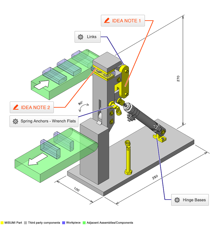
No.000162 Grip and Rotate Feed Mechanism
33
33
Grip and feed motion with a single cylinder
Related Category


Spring Anchors - Wrench Flats, with Notch

| Product name | Spring Anchors/Wrench Flats/with Notch |
|---|---|
| Part number | SAIPOK8-30 |
| Features | Posts for Tension Springs with Notched Hole which facilitates hooking of the tension springs. |
* Orange colored cells in the table below indicate the part numbers used in this example.
Selection criteria
Suitable for mounting the springs with swinging and tensile load
Available sizes
■Spring Anchors - Wrench Flats, with Notch / Full Threaded Under Head
| Material | Surface Treatment | Accessory |
|---|---|---|
| EN 1.1191 Equiv. | Black Oxide | Nut one pc (JIS Class 1) SWCH Equiv. |
| EN 1.4301 Equiv. | - | Nut one pc (JIS Class 1) EN 1.4301 Equiv. |
■Sizes and Dimensions
| O.D. | Overall Length | Thread Section Length (overall length - shown below) | Screw Dia. (Coarse) | Spring Latch Hole DIa. | Notched Slot Width | |||||||
|---|---|---|---|---|---|---|---|---|---|---|---|---|
| 15 | 20 | 25 | 30 | 40 | 50 | 60 | 70 | |||||
| Ø4 | ○ | ○ | ○ | ○ | - | - | - | - | 8.5 | M4 | Ø1.5 | 1 |
| Ø5 | ○ | ○ | ○ | ○ | ○ | - | - | - | 9 | M5 | Ø2 | |
| Ø6 | - | ○ | ○ | ○ | ○ | ○ | - | - | 10 | M6 | ||
| Ø8 | - | - | ○ | ○ | ○ | ○ | ○ | ○ | 12 | M8 | Ø3 | 1.5 |
| Ø10 | - | - | - | ○ | ○ | ○ | ○ | ○ | 15 | M10 | Ø4 | 2 |
| Ø12 | - | - | - | - | ○ | ○ | ○ | ○ | 17 | M12 | Ø5 | 2.5 |

Links General Purpose
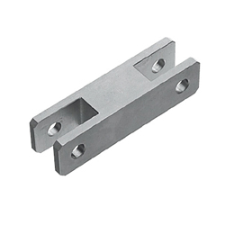
| Product name | Links/Both Ends Female Notch |
|---|---|
| Part number | LACG4-55-5 |
* Orange colored cells in the table below indicate the part numbers used in this example.
Selection criteria
Suitable as an application for an economical completed product of the link mechanism parts
Available sizes
■Links General Purpose Round
| Material | EN 1.0038 Equiv. |
|---|
■Sizes and Dimensions
| Shaft Bore Dia. (Equal Dia.) | Shaft Bore Center Distance | Width | Thickness | ||||||
|---|---|---|---|---|---|---|---|---|---|
| Inner dimensions | Outer dimensions | ||||||||
| 5 | 6 | 9 | 12 | 16 | 19 | ||||
| Ø3 | 40 ~ 100 | 20 | ○ | ○ | ○ | - | - | - | 20 |
| Ø4 | |||||||||
| Ø5 | 50 ~ 100 | 25 | ○ | ○ | ○ | ○ | - | - | 25 |
| Ø6 | |||||||||
| Ø8 | 50 ~ 120 | 28 | - | - | ○ | ○ | ○ | ○ | 28 |
| Ø10 | |||||||||
| Ø12 | 60 ~ 120 | 32 | - | - | - | ○ | ○ | ○ | 32 |
| Ø13 | |||||||||
| Ø14 | |||||||||
| Ø15 | |||||||||
* Please see the product pages for detailed dimensions.
Accuracy Info
■Accuracy of Links
Shaft Bore DIA. Tolerance: H7

Hinge Bases - A, H Compact Type
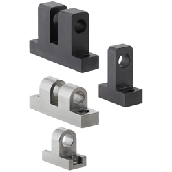
| Product name | Hinge Bases/Standard/Miniature Type |
|---|---|
| Part number | HGHAM6-W6-H20 |
| Features | Hinge Bases with the width (A dim.) shortened. They can be used in limited spaces. |
* Orange colored cells in the table below indicate the part numbers used in this example.
Selection criteria
Suitable for using as swinging parts of the cylinder
Available sizes
■Hinge Bases - A, H Compact T-Shaped Type
| Material | Surface Treatment |
|---|---|
| EN 1.1191 Equiv. | Black Oxide |
| Electroless Nickel Plating |
■Sizes and Dimensions
| Shaft Bore Dia. | Shaft Bore Length | Shaft Bore Height H | Overall Length | Overall Height | Width |
|---|---|---|---|---|---|
| 1mm increments | |||||
| Ø3 | 3 ~ 6 | 11 ~ 20 | 22 | H + 4.5 | 9 |
| Ø4 | |||||
| Ø5 | 4 ~ 10 | 12 ~ 25 | 25 | H + 6 | 12 |
| Ø6 | 5 ~ 10 | ||||
| Ø8 | 6 ~ 15 | 16 ~ 30 | 32 | H + 8 | 16 |
| Ø10 | 8 ~ 15 | 16 ~ 35 | |||
| Ø12 | 18 ~ 35 | H + 9.5 | 19 | ||
| Ø13 | 12 ~ 18 | 20 ~ 35 | 38 | ||
| Ø14 | 23 ~ 35 | H + 12.5 | 25 | ||
| Ø15 | |||||
| Ø16 | |||||
| Ø20 | 15 ~ 25 | 27 ~ 40 | 50 | H + 15 | 30 |
| Ø25 | 20 ~ 25 | 28 ~ 45 | H + 16 | 32 | |
Accuracy Info
■Accuracy of Hinge Bases
Shaft Bore Dia. Tolerance: H7


-

-
 Terms of use of CAD data and simplified drawing data
- These terms and conditions (hereinafter referred to as “the Terms") set forth the conditions for downloading CAD data and simplified drawing data provided by MISUMI Corporation (hereinafter referred to as "MISUMI") via www.misumi-europe.com operated by MISUMI Europa GmbH(hereinafter referred to as the "Website"). By downloading CAD data and simplified drawing data posted on the Website (hereafter referred to as “Data”), customers are deemed to have agreed to these Terms.
- 1. Purpose of Use
-
MISUMI offers the following:
1)CAD data found on the Website (3D CAD data, 3D Intermediate data and 2D CAD data) for the purpose of informing customers of the characteristics of the products offered by MISUMI or a manufacturer affiliated with MISUMI for use in their designs.
2)Simplified drawing data (in PDF format) for the purpose of checking the specifications of products. - 2. Characteristics of Data
- There may be a discrepancy in certain characteristics of products (for example: tolerance, surface roughness, chamfer, etc.) between the Data and the actual product. Furthermore, for the purpose of reducing the file size of the Data, some information such as oil groove shapes, threads, or spring shapes, may be removed from the Data.
- 3. Disclaimer
- MISUMI carefully creates the Data but makes no warranty as to the quality, accuracy, functionality, safety, reliability, etc., of the Data. MISUMI may at any time, and with no prior notice to customers, revise or delete Data. MISUMI assumes no responsibility for any damage or loss resulting from any revision or deletion of the Data, or any errors in said data. Customers are solely responsible for all aspects of their own designs, including those made using the Data. MISUMI may provide customers with design example data on the Website, but the quality, accuracy, functionality, safety, reliability, etc., of such data are not guaranteed. MISUMI may, at any time, and in its sole discretion, request that the customer cease its use of or destroy the Data in its possession. MISUMI may request the customer provide MISUMI documentation of such destruction.
- 4.Prohibited Acts
-
Customers or users of the Data, are prohibited from the following acts regarding the Data, in whole or in part:
(1)Requesting quotations or placing orders for products with third parties other than those authorized by MISUMI or its affiliates;
(2)Receiving quotations or orders for products from third parties by providing the Data to a third party or using the Data in their own business;
(3)Displaying links to the Website related to the Data on their own websites, etc., without consent of MISUMI or its affiliates;
(4)Using or reproducing the Data beyond the scope of the above-stated Purpose of Use;
(5)Modifying, altering, tampering with, translating, or adapting the Data;
(6)Selling, transferring, lending, sublicensing, or providing the Data to third parties in any way without consent of MISUMI or its affiliates;
(7)Altering the content, reverse engineering, decompiling, disassembling, or analyzing the Data;
(8)Publicly disclosing or exhibiting the Data without consent of MISUMI or its affiliates;
(9)Using the Data for the purpose of providing products and services identical or similar to those of MISUMI or its affiliates;
(10)Performing acts that interfere with the proper functioning of this Website, such as acquiring Data in bulk. - 5. Copyright
-
All title and copyright in and to any information contained in the Data are owned by MISUMI or the relevant manufacturer affiliated with MISUMI and are protected by applicable copyright laws and international treaties. By downloading Data, the customer acquires no ownership rights of any kind in the intellectual property contained within. Without prior approval from MISUMI, no part of the Data may be utilized (reproduced, modified, reverse-engineered, uploaded, presented, sent, distributed, licensed, sold, or published) for any purpose other than that mentioned above.
In the event Data is found to have been to be used for any purpose other than that mentioned above or against any applicable laws or the Terms, MISUMI may pursue any legal remedy available to it, which may result in forbidding the offending user from using the Data or accessing the Website. - 6. Third-Party Data
- MISUMI offers some Data provided by third parties. Such Data may be subject to separate terms and conditions, in addition to these terms. MISUMI makes no guarantee or warranty regarding Data from third parties.
- 7. Export Control
- Customers shall comply with all applicable laws and regulations regarding the export of the Data.
- 8. Amendments to the Terms
- MISUMI may, at any time, and in its sole discretion, modify these terms and conditions; any such modification will be effective immediately.
- 9. Severability
- If any term or provision of these Terms is invalid, illegal, or unenforceable in any jurisdiction, such invalidity, illegality, or unenforceability shall not affect any other term or provision of these Terms or invalidate or render unenforceable such term or provision in any other jurisdiction. Section 139 BGB (German Civil Code) shall not apply.
- 10.Miscellaneous
-
In the event that Customers violate the Terms, MISUMI and/or MISUMI Europa GmbH shall be entitled to claim the damages and expenses (including attorney's fees) incurred by such violation against the Customers.
These Terms and any disputes arising in connection therewith shall be exclusively governed by and construed in accordance with the laws of the Federal Republic of Germany, without regard to its conflicts of law principles. The courts located in Frankfurt am Main/Germany shall have exclusive jurisdiction to adjudicate any dispute arising in connection with these Terms. By downloading the Data, you agree to submit to the exclusive and personal jurisdiction of the courts located in Frankfurt am Main/Germany. - Revised: September 21, 2025
CAD Data Download (Unit Assembly)
CAD Data Download: File Format
Cautions on the CAD data
-
Assembly data shows the assembly drawings in the concept design phase. The sole purpose of the data is to explain the structure and functionality of the assembly and is not considered nor to be used as a final design.
You will need to edit the Data so that it meets your specific design conditions. -
The CAD data unit assembly consists of sub-assemblies.
Each sub-assembly unit can be used as it is or can be edited. - The Data for fabricated parts is based on easy-to-edit dimensions and shapes in sketches and histories.
- The Data including the third-part components are made by the Company.
* The part in the frame is a sub-assembly unit.
-

- * Unit assembly CAD data consists of some sub-assemblies.
Each sub-assembly unit can be used as it is or can be edited.
Application Overview
Purpose
- Purpose
- Feeding the workpiece after rotating 90°.
- Operation
- On the output side of the cylinder, the clamped workpiece is unclamped at the first return stroke after the swing arm tumbles hitting the stopper surface and comes to a halt. At the cylinder return side, the arm rises up in an unclamped condition, hits the stopper surface and comes to a halt. When the cylinder moves again toward the output side, the workpiece is clamped at the beginning of the stroke.
Target workpiece
- Shape: Small-size battery case
- Size: W22 x L45 x H10mm
- Weight: 0.03kg
Design Specifications
Operating Conditions or Design Requirements
- Grips the workpiece after receiving it.
- Rotation: 90°
- Work head drop: 100mm
Required Performance
- Locating accuracy: ±1mm
Selection Criteria for Main Components
- Cylinder
- Small-size, double-acting
- Tension spring
- Auxiliary part for initially performing the clamp motion/Retaining workpieces during revolution motion .
Spring constant k = 0.22N/mm
Spring tensile length l = 11.7mm
Workpiece retaining force = k x l = 2.57N
- Auxiliary part for initially performing the clamp motion/Retaining workpieces during revolution motion .
Design Evaluation
Verification of main components
- Verify the cylinder thrust and spring load from the load moment.
- Check the force to operate the arm.
- Conditional values: Workpiece mass m = 0.03kg
Gravitational acceleration = 9.8m/s²
Cylinder diameter = 16mm
Supply pressure = 0.5Mpa
Mechanical efficiency = 80%
Distance between the tension spring shaft and the rotary shaft at the chuck release: L1 = 10.5mm
Distance between the tension spring shaft and the rotary shaft after the workpiece is moved: L2 = 28.3mm
Distance between the tension spring shaft and the rotary shaft at the chuck release: L3 = 38.4mm
Distance between the cylinder shaft and the rotary shaft after the workpiece is moved: L4 = 17.3mm
Tension spring natural length L = 80mm
Initial tension of the tension spring: F1 = 3.73N
Length of the tension spring at the chuck release: L5 = 114mm
Length of the tension spring after revolution of the workpiece: L6 = 99mm
Spring constant k = 0.22N/mm
Tension of the tension spring at the chuck release: F2 = F1 + k x (L5 - L) = 3.73 + 0.22 x (114 - 80) = 11.2N
Tension of the tension spring at the chuck release: F3 = F1 + k x (L6 - L) = 3.73 + 0.22 x (99 - 80) = 7.9N
Cylinder thrust F4 = 101N
Cylinder thrust F5 = 75N
Moment ratio.
In chuck operation/arm revolution.
Moment generated by the cylinder thrust. From M1 = F4 x L3, M1 = 101 x 38.4 = 3879N・mm
Moment generated by the spring. From M2 = F2 x L1, M2 = 11.2 x 10.5 = 117.6N・mm
When the arm is pulled up after revolution of the workpiece.
Moment generated by the cylinder thrust. From M3 = F5 x L4, M3 = 75 x 17.3 = 1297.5N・mm
Moment generated by the spring. From M4 = F3 x L2, M4 = 7.9 x 28.3 = 223.6N・mm
From calculations shown above, we obtain M1 >> M2 and M3 >> M4, which shows that the arm drive operates without delay.
- Conditional values: Workpiece mass m = 0.03kg
Other Design Consideration
- Shape of the shoulder pad for locating the main revolution arm.
- Link shape at the chuck part that fixes the grip release angle and grip close angle.
Explore Similar Application Examples
Page
-
/
-


Payment Method


On-Demand Manufacturing
Certificates


Copyright © MISUMI Corporation All Rights Reserved.