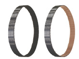
Timing Belt
| Product name | Timing Belts - MXL, XL, L, H |
| Model number | TUN165L050 |
| Characteristic | General purpose timing belts for transmission. Although some tooth fabrics for MXL and XL rubber belts are changed to comply with the bear-back specifications, it does not affect the performance. |
* Orange colored cells in the table below indicate the part numbers that were actually used in this app. example.
Selection criteria
Transmit torque from driving to driven pulley.
Back to page top
Risk info.
A pulley layout enabling replacements
Back to page top
Available sizes
■Timing Belts - MXL / XL / L / H
| Material | MXL | XL | L | H |
| Tooth surface cover | Tooth rubber | Core wire |
| Nylon canvas | Chloroprene
Rubber | Glass fiber cord
S / Z Alternately Twisted Continuous | ○ | ○ | ○ | ○ |
| Polyurethane | Polyurethane | MXL: Kevlar
XL ・ L: Steel cord | ○ | ○ | ○ | - |
■Reference dimensions
| Belt type | Pitch | Belt width | Belt length reference |
| MXL | 2.032 | 4.8, 6.4, 9.5, 12.7 | 100 - 1100 |
| XL | 5.08 | 6.4, 7.9, 9.5, 12.7 | 200 - 2100 |
| L | 9.525 | 12.7, 19.1, 25.4, 38.1 | 300 - 1800 |
| H | 12.7 | 19.1, 25.4, 38.1, 50.8 | 600 - 4300 |
Back to page top
Selection steps
■Timing belt selection procedure
* Timing belt selection is made together with timing pulley
- Determining of usage conditions
- Designed power ・ Rotational speed ・ Interim shaft distance ・ motion pattern, etc.
↓
- Belt (pulley) interim selection
- Belt type ・ Belt width
↓
- Verifying specification compatibility
-
- Verifying calculated shaft distance, etc.
- Verifying tension and load
Performance info.
■Load info. of timing belt
| Belt type | Small pulley rotational speed (rpm) | Designed power (kW) |
| MXL, XL, L, H, T5, T10 | 10 - 20000 | 0.01 - 800 |
Back to page top
Technical calculations
■Technical calculations
Back to page top
Timing Pulley
| Product name | Timing Pulleys L Type |
| Model number | ATPA19L050-A-N30 |
| Characteristic | New! METRIC/ INCH Bores Available! |
* Orange colored cells in the table below indicate the part numbers that were actually used in this app. example.
Selection criteria
Transfer rotary motion. Aluminum type selected for weight reduction purposes.
Back to page top
Risk info.
Accuracy degradation due to wear over time.
Back to page top
Available sizes
■Timing Pulleys L Type
| Material | Surface treatment | Tooth type / Belt width |
| MXL | XL | L | H |
| Pulley | Flange | 4.8 | 6.4 | 9.5 | 12.7 | 6.4 | 7.9 | 9.5 | 12.7 | 12.7 | 19.1 | 25.4 | 38.1 | 19.1 | 25.4 | 38.1 | 50.8 |
MXL, XL:
EN AW-2017 Equiv.
L, H:
EN AW-7075 Equiv. | EN AW-5052 Equiv. | Clear anodize | ○ | ○ | ○ | ○ | ○ | ○ | ○ | ○ | ○ | ○ | ○ | ○ | ○ | ○ | ○ | ○ |
| Black anodize | ○ | ○ | ○ | ○ | ○ | ○ | ○ | ○ | ○ | ○ | ○ | ○ | ○ | ○ | ○ | ○ |
| Hard anodize | ○ | ○ | ○ | ○ | ○ | ○ | ○ | ○ | ○ | ○ | ○ | ○ | ○ | ○ | ○ | ○ |
Electroless
nickel plating | ○ | ○ | ○ | ○ | ○ | ○ | ○ | ○ | ○ | ○ | ○ | ○ | ○ | ○ | ○ | ○ |
| EN 1.1191 Equiv. | EN 1.0330 Equiv. | - | - | ○ | ○ | - | ○ | - | ○ | ○ | ○ | ○ | ○ | ○ | ○ | ○ | ○ | ○ |
Black
oxide | - | ○ | ○ | - | ○ | - | ○ | ○ | ○ | ○ | ○ | ○ | ○ | ○ | ○ | ○ |
Electroless
nickel plating | - | ○ | ○ | - | ○ | - | ○ | ○ | ○ | ○ | ○ | ○ | ○ | ○ | ○ | ○ |
| EN 1.4301 Equiv. | EN 1.4301 Equiv. | - | - | ○ | ○ | - | ○ | - | ○ | ○ | - | - | - | - | - | - | - | - |
■Pulley number of teeth and shaft bore DIA.
| Belt type | Shape | Number of teeth | Pitch circle DIA. | Shaft bore DIA. |
| MXL | K, A, B | 14 - 72 | O9.6 - 46.57 | O3 - 35 |
| XL | A, B | 10 - 72 | O16.17 - 116.43 | O4 - 80 |
| L | A, B, D | 10 - 72 | O30.32 - 218.30 | O6 - 100 |
| H | A, B, D | 14 - 72 | O58.60 - 291.06 | O12 - 100 |
K: With collar
A: No hub
B: With hub
D: With hub Relieved
Back to page top
Selection steps
■Timing pulley selection steps
* Timing pulley selection is made at the same time as the timing belt.
- Determining of usage conditions
- Design power ・ Rotational speed ・ Rotation ratio ・ Interim shaft distance, Motion pattern, etc.
↓
- Temporary selection of pulley (Belt)
- Tooth profile ・ Belt width
↓
- Verifying specification compatibility
-
- Verifying calculated shaft distance, etc.
- Verifying tension・Load
Back to page top
Accuracy Info
■Timing pulley accuracy
Shaft bore tolerance: H7
Back to page top
Technical calculations
■Technical calculations
Back to page top
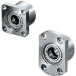
Bearings with Housing
| Product name | Standard Length/Double Bearings/Retained |
| Model number | BGRBB6007ZZ-50 |
* Orange colored cells in the table below indicate the part numbers that were actually used in this app. example.
Selection criteria
Compact double bearing type with high bearing performance
Back to page top
Available sizes
■Bearings with Housings - Standard Length, Double Bearings, Retained
| Flange Shape | Material | Surface treatment |
| Bearing | Housing | Retaining ring | Housing |
Round type
Square type
Compact type | Steel | EN 1.1191 Equiv. | Spring steel | Black oxide |
| EN 1.4301 Equiv. | Electroless nickel plating |
| EN AW-2017 Equiv. | EN 1.4301 Equiv. | Clear anodizing |
| Stainless |
| EN 1.4301 Equiv. | - |
■Sizes
| Shaft bore DIA. | Bearing
part number | Seal | Overall length | Pilot
O.D. |
| O30 | 6806 | Double shielded
Non-contact
rubber seal
Contacting
rubber seal | 35 | 50 | O50 |
| 6906 | 35 | 50 | O54 |
| 6006 | 40 | 60 | O62 |
| 6206 | 50 | 60 | O70 |
| O35 | 6007 | 50 | 60 | O70 |
| 6207 | 60 | 80 | O84 |
| O40 | 6008 | 60 | 70 | O78 |
| 6208 | 60 | 80 | O92 |
Back to page top
Accuracy Info
■Accuracy of bearing housing
Pilot O.D. tolerance: g7
Seating face - Pilot perpendicularity: 0.01
Back to page top
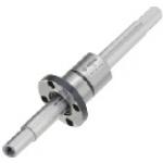
Ball Spline
* Orange colored cells in the table below indicate the part numbers that were actually used in this app. example.
Selection criteria
Suitable for a transmission element when linear and rotary motion are needed at the same time.
Back to page top
Available sizes
■Ball Splines -Both Ends Stepped Tapped
Spline
Shaft | Material | EN 1.3505 Equiv. | EN 1.4125 Equiv. |
| Hardness | 58HRC ~ | 55HRC ~ |
| Nut | Material | EN 1.722515 Equiv. | EN 1.4125 Equiv. |
| Hardness | 58HRC ~ | 55HRC ~ |
| Shape | Round flange | ○ | ○ |
| Compact flange | ○ | - |
| Straight | ○ | ○ |
■Dimensions
| Spline shaft | Nut |
| Name No. | Shaft DIA. | Overall length | Pilot DIA. |
| 10 | O10.4 | 60 - 600 | O21 |
| 13 | O13.4 | 60 - 600 | O24 |
| 16 | O16.6 | 70 - 600 | O31 |
For EN 1.4125 Equiv. spline shaft max. overall length is 390mm.
Back to page top
Selection steps
■Ball spline selection steps
- Determine application conditions
- (Load, Torque, Feed distance, Life)
↓
- Temporarily select ball spline specifications
- (Temporarily select spline shaft DIA., spline shaft length, overall length based on app. conditions)
↓
- Verify basic safety
-
Back to page top
Accuracy Info
■Accuracy of ball spline shaft
(μm)
Name
No. | Spline
Shaft DIA. | Nut O.D. runout | Spline shaft center runout (Max.) |
| (Max.) | Length | - 200 | 201 - 315 | 316 - 400 | 401 - 500 | 501 - |
| 10 | O10.4 | 33 | 59 | 83 | 103 | 82 | 102 |
| 13 | O13.4 | 39 | 56 | 71 | 83 | 62 | 75 |
| 16 | O16.6 |
Back to page top
Performance info.
■Ball spline load rating
Name
No. | Basic torque rating | Basic load rating |
| Dynamic (Nm) | Static (Nm) | Dynamic (kN) | Static (kN) |
| 10 | 11 | 21 | 2.4 | 4.3 |
| 13 | 20 | 37 | 3.3 | 5.9 |
| 16 | 51 | 93 | 6.2 | 11.1 |
Back to page top
Technical calculations
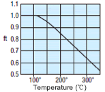
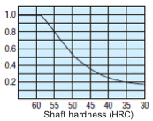
Ball spline running life is calculated with the formula below.
- L: Life (km)
- ft: Temp. factor
- fh: Hardness factor
- fp: Load rating ratio
- fw: Load factor
- L0: Rated life (50km)
- C: Basic dynamic load rating (N)
- F: Applicable radial load (N)
- Ct: Basic dynamic torque rating (N・m)
- T: Applicable torque (N・m)
Ball spline life time is calculated with the formula below.
- Lh: Run hours (hr)
- L: Life (km)
- St: Stroke length (mm)
- n: Number of cycles per minute (cpm)
■Load rating ratio (fp)
| Name No. | Spline shaft DIA. | Distributed load | Direct download |
| 10 | O10.4 | 1 | 0.71 |
| 13 | O13.4 | 1 | 0.71 |
| 16 | O16.6 | 1 | 0.68 |
■Load factor (fw)
| Application conditions | Load factor (fw) |
No vibration or shocks
(Low speed 1 ~ 2 15m/min or less) | 1 - 2 |
Some vibrations and shocks
(Med. speed 2 ~ 3 60m/min) | 2 - 3 |
Severe vibrations and shocks
(High speed 3 and over 60m/min or over) | 3 - |
Back to page top
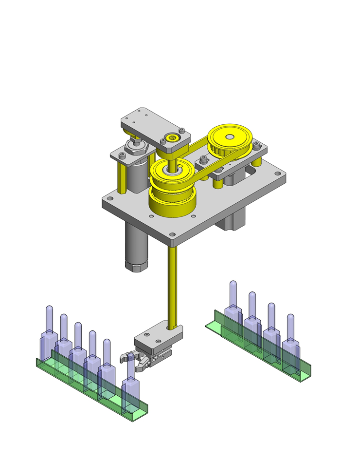
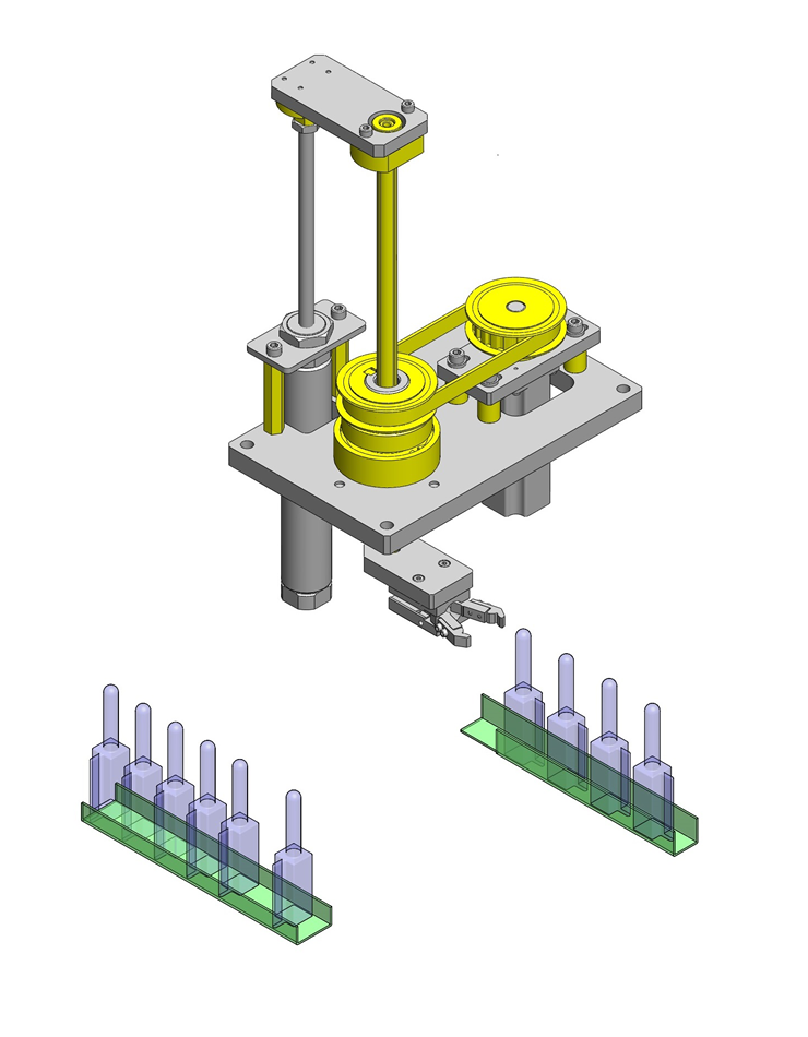
IDEA NOTE Transmit rotational power to the ball spline nut
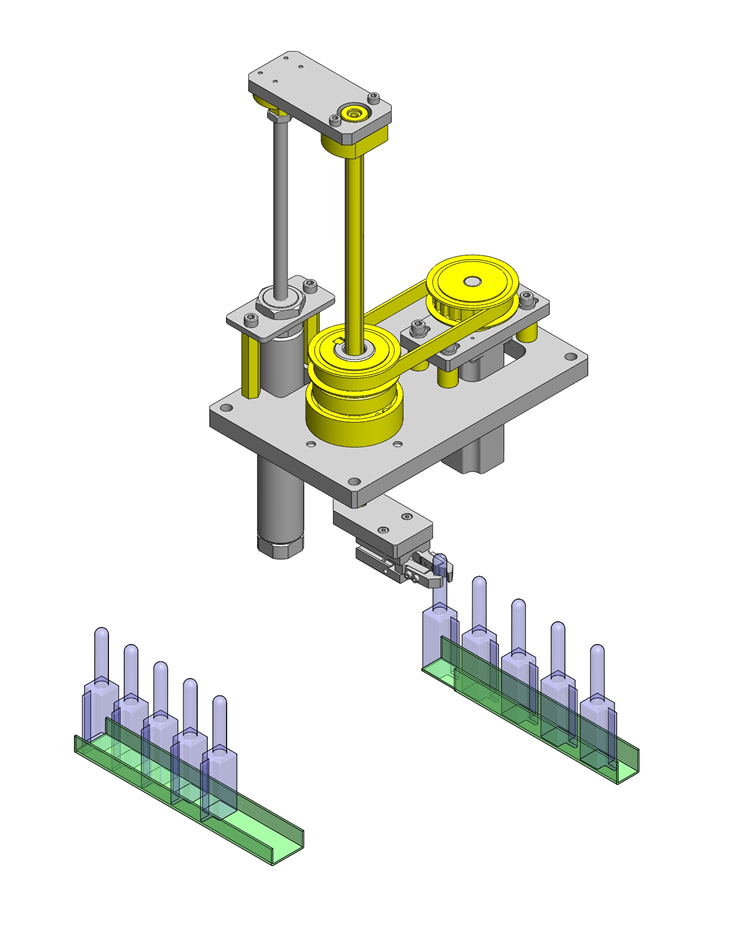
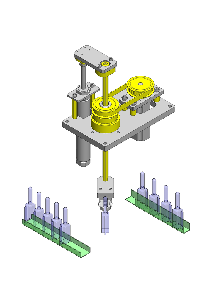
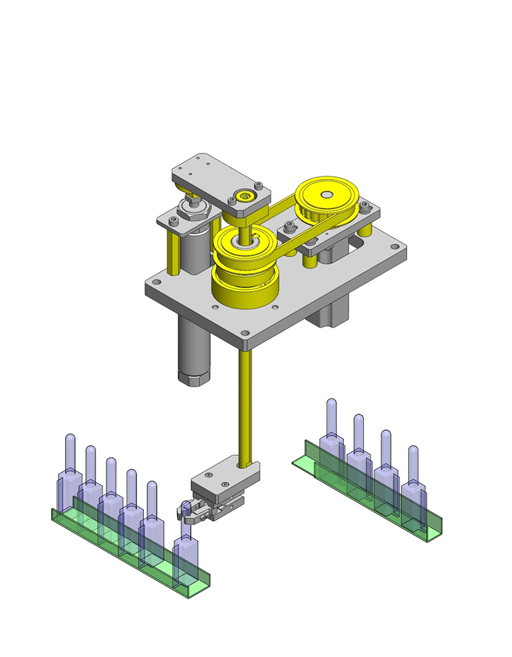
This app. example uses a ball splines with flanged type nut.
Flanged nut is mounted on a hollow shaft, and rotation is transmitted via a pulley.


