- inCAD Library Home
- > No.000206 Rollers to Connect Between Conveyors
No.000206 Rollers to Connect Between Conveyors
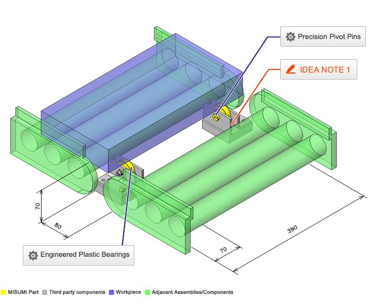
Provide roller support to workpiece when transporting between conveyors.
Related Category
- * Unit assembly CAD data consists of some sub-assemblies.
Each sub-assembly unit can be used as it is or can be edited.
Application Overview
Purpose
- An auxiliary roller is inserted to prevent workpiece fall-off in the case where there is gap between conveyors.
Points for use
- The larger the sprocket, the more likely clearance is generated between conveyors.
Target workpiece
- Pallet
- External dimensions: W 200 x D 400 x H 60 mm
- Pallet weight: 10 kg
Design Specifications
Operating Conditions or Design Requirements
- External dimensions: W 80 x D 390 x H 70 mm
Required Performance
- Allowable load of one bearing: 245 N
- Pallet load: 100 N
Selection Criteria for Main Components
- Bearing
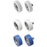
- Selected as an auxiliary roller.
- Allowable load of one bearing: 245 N
Design Evaluation
Verification of main components
- Verify the bearing load capacity for withstanding workpiece load.
- Pallet load: (= 100 N) < Allowable load of one bearing (= 245 N) x 2 (locations)
100 N < 490 N Thus, being satisfied. - Thus, capable of withstanding the weight of a heavy load exceeding the assumption in the range up to 490 N.
- Pallet load: (= 100 N) < Allowable load of one bearing (= 245 N) x 2 (locations)
Other Design Consideration
- An auxiliary roller is inserted to protect workpieces from falling off in the case of clearance between conveyors.
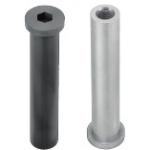
- Hinge pins are utilized to mount the bearings on brackets in between the gap form by conveyors.
Explore Similar Application Examples
Page
-
/
-


