
- inCAD Library Home
- > No.000150 90° Rotational transfer mechanism
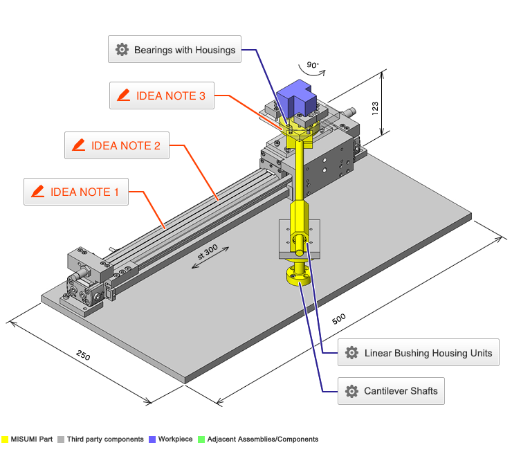
No.000150 90° Rotational transfer mechanism
65
Rotate workpiece 90 degrees while transporting
Related Category


Cantilever Shafts
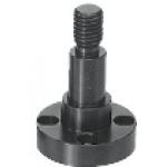
| Product name | Cantilever Shafts/Flanged/w Threaded End |
|---|---|
| Part number | PFXFC10-15-F8-M6 |
Selection criteria
Effective as a pin in rotational link mechanisms that have oscillating motion
Available sizes
■Cantilever Shafts (Lock Nut Type)
| Material | Surface Treatment |
|---|---|
| EN 1.1191 Equiv. | Black Oxide |
| Electroless Nickel Plating | |
| EN 1.4301 Equiv. | - |
■Sizes and Dimensions
| Pin Dia. (mm) | Shaft section length (Configure in 1mm increments) | Screw DIA. (M Coarse) |
|---|---|---|
| 6 | 5 - 100 | 4, 5, 6 |
| 8 | 5, 6, 8 | |
| 10 | 6, 8, 10 | |
| 12 | 10 - 150 | 6, 8, 10, 12 |
| 13 | ||
| 15 | 8, 10, 12, (15) | |
| 16 | ||
| 17 | 10, 12, (15), 16 | |
| 18 | ||
| 20 | 10, 12, (15), 16, 20 | |
| 22 | ||
| 25 | 10, 12, (15), 16, 20, 24, (25) | |
| 30 | 12, (15), 16, 20, 24, (25), 30 | |
| 35 | ||
| 40 | ||
| 50 |
* M15 and M25 of ( ) dimensions of Screw Dia. will be fine threads.
Accuracy Info
■Accuracy of Cantilever Shafts
Perpendicularity: 0.02
(mm)
| Pin Dia. | O.D. Tolerance |
|---|---|
| g6 | |
| 6 | -0.004 -0.012 |
| 8 ・ 10 | -0.005 -0.014 |
| 12 - 18 | -0.006 -0.017 |
| 20 - 30 | -0.007 -0.020 |
| 35 - 50 | -0.009 -0.025 |

Bearings with Housings

| Product name | Direct Mount/Standard/Retained |
|---|---|
| Part number | BGRA6000ZZ |
Selection criteria
Low cost
Available sizes
■Bearing with housing (With retaining ring, Round type)
| Material | Surface Treatment | |
|---|---|---|
| Bearing | Holder | Holder |
| Steel | EN 1.1191 Equiv. | Black Oxide |
| Electroless Nickel Plating | ||
| EN AW-2017 Equiv. | Clear Anodize | |
| Stainless Steel | ||
| EN 1.4301 Equiv. | - | |
■Bearing Type
| Bearing No. | Shaft Bore Dia. | I.D. (Bearing O.D.) | Seal |
|---|---|---|---|
| 6900 | 10 | 22 | ZZ (Double shielded) VV (Non-contact rubber seal) DD (Contact rubber seal) |
| 6000 | 26 | ||
| 6200 | 30 |
Accuracy Info
■Accuracy of bearings with housing
(mm)
| Shaft Dia. | I.D. | |
|---|---|---|
| I.D. Tolerance H7 | ||
| 8 | 19 | +0.021 0 |
| 22 | ||
| 24 | ||
| 10 | 19 | |
| 22 | ||
| 26 | ||
| 30 | ||
| 12 | 21 | |
| 24 | ||
| 28 | ||
| 32 | +0.021 0 |

Linear Bushing Housing Units

| Product name | Linear Bushings with Pillow Blocks/Double Bushings |
|---|---|
| Part number | LHSSKW10 |
| Features | The compact type is Max. 6mm lower in height (H dimension) and Max. 3mm smaller in width (W dimension) than the Standard Type. |
Selection criteria
Includes the bushing and the housing
Available sizes
■Linear Bushing Housing Unit (Tall Blocks Double, Compact Type)
| Linear Bushing Used | Holder | |
|---|---|---|
| Material | Surface Treatment | |
| Compact | Aluminum Alloy | Clear Anodize |
■Sizes and Dimensions
| I.D. (mm) | Overall Length (mm) | Mounting Screw Dia. |
|---|---|---|
| 6 | 46 | M4 |
| 8 | 56 | |
| 10 | 68 | M5 |
| 12 | 70 | |
| 16 | 84 | M6 |
Selection Steps
■Linear Bushings with Pillow Blocks Selection Steps
- Determine Application Conditions
- (Load, Operational Pattern, Life hours)
↓
- Temporarily select linear bushing specifications
- (Shaft dia. and length are temporarily selected according to the conditions of use.)
↓
- Basic safety check
-
- ●Basic Static Load Rating
- ●Basic Dynamic Load Rating
- ●Allowable Static Moment
- ●Operating Life
↓
- Considerations Based on Required Performance
- ●Life Variations Due to Temperature Changes
Accuracy Info
■Accuracy of Linear Bushings with Pillow Blocks
(mm)
| I.D. | I.D. Tolerance | Tolerance of Height from Table Top |
|---|---|---|
| 6 | 0 -0.010 | ±0.02 |
| 8 | ||
| 10 | ||
| 12 | ||
| 16 |
Performance info.
■Speeds / Loads (Load Info.) of Linear Bushings with Pillow Blocks
| I.D. (mm) | Basic Load Rating | |
|---|---|---|
| Basic Dynamic Load Rating (N) | Basic Static Load Rating (N) | |
| 5 | 167 | 206 |
| 6 | 206 | 265 |
| 8 | 265 | 380 |
| 10 | 372 | 549 |
| 12 | 412 | 598 |
| 13 | 510 | 784 |
| 16 | 775 | 1180 |
| 20 | 882 | 1370 |
| 25 | 980 | 1570 |
| 30 | 1570 | 2740 |
| 35 | 1670 | 3140 |
| 40 | 2160 | 4020 |
| 50 | 3820 | 7940 |
Technical calculations
■Life of Flanged Linear Bushings
When the linear system is loaded in linear reciprocating motion, scaly damages called flaking appear due to material fatigue as the repeated stress is applied on the rolling elements and the rolling contact surfaces constantly. Total travel distance until the first flaking occurs is called the life of linear system.
Rated life can be calculated with the basic dynamic load rating and the actual load applied on the linear bushings, as shown below.
- L: Rated Life (km)
- fH: Hardness Factor (See Fig.1)
- fT: Temperature Factor (See Fig. 2)
- fC: Contact Factor (See Table-3)
- fW: Load Factor (See table-4)
- C: Basic Dynamic Load Rating (N)
- P: Applicable Load (N)
●Hardness factor (fH)
For liner system applications, sufficient hardness is required for ball contact shafts. Inappropriate hardness causes less allowable load, resulting in shorter life.
Fig.-1 Hardness Factor
●Temperature factor (fT)
When the temperature of linear Bushings exceed 100°C, hardness of blocks and rails will be reduced, causing reduction of life. Please compensate the life rating with temperature factor.
Fig.-2. Temperature factor
●Contact factor (fC)
In general, it is common to use two or more linear bushings on one linear shafts. In these cases, the load on each bushing will vary depending on the machining precision and will not have equally distributed loads. As a result, the allowable load per bushing will vary depending on the number of bushings used on shaft.
Table-3. Contact Factor
| Number of bearings installed on one shaft. | Contact factor fC | |
|---|---|---|
| 1 | 1 | |
| 2 | 0.81 | |
| 3 | 0.72 | |
| 4 | 0.66 | |
| 5 | 0.61 | |
●Load Factor (fW)
To calculate load applied to the linear bushings, in addition to the object weight, the inertia force attributed to the motion velocity, moment loads and the variations of each over time must be obtained. However, for reciprocating motion applications, it is difficult to obtain accurate calculation due to the effects of vibrations and shocks. Therefor, use Table2 to simplify the life calculations.
| Conditions of Use | fw |
|---|---|
| No external shocks or vibrations and speed is low 15m/min or less | 1.0 ~ 1.5 |
| No significant shocks or vibration and med. speed 60m/min or less | 1.5 ~ 2.0 |
| External shocks and vibrations exist and the speed is high 60m/min or over | 2.0 ~ 3.5 |
Life in hours can be obtained by calculating the travel distance per hour. Then the stroke length and stroke cycles are fixed, use the equation below.
- Lh: Life (hr)
- L: Rated Life (km)
- Ls: Stroke length (m)
- n1: Number of cycles per minute (cpm)


IDEA NOTE Swinging fulcrum configuration
There are built-in bearings at the constraint fulcrum and rotational center.


-

-
 Terms of use of CAD data and simplified drawing data
- These terms and conditions (hereinafter referred to as “the Terms") set forth the conditions for downloading CAD data and simplified drawing data provided by MISUMI Corporation (hereinafter referred to as "MISUMI") via www.misumi-europe.com operated by MISUMI Europa GmbH(hereinafter referred to as the "Website"). By downloading CAD data and simplified drawing data posted on the Website (hereafter referred to as “Data”), customers are deemed to have agreed to these Terms.
- 1. Purpose of Use
-
MISUMI offers the following:
1)CAD data found on the Website (3D CAD data, 3D Intermediate data and 2D CAD data) for the purpose of informing customers of the characteristics of the products offered by MISUMI or a manufacturer affiliated with MISUMI for use in their designs.
2)Simplified drawing data (in PDF format) for the purpose of checking the specifications of products. - 2. Characteristics of Data
- There may be a discrepancy in certain characteristics of products (for example: tolerance, surface roughness, chamfer, etc.) between the Data and the actual product. Furthermore, for the purpose of reducing the file size of the Data, some information such as oil groove shapes, threads, or spring shapes, may be removed from the Data.
- 3. Disclaimer
- MISUMI carefully creates the Data but makes no warranty as to the quality, accuracy, functionality, safety, reliability, etc., of the Data. MISUMI may at any time, and with no prior notice to customers, revise or delete Data. MISUMI assumes no responsibility for any damage or loss resulting from any revision or deletion of the Data, or any errors in said data. Customers are solely responsible for all aspects of their own designs, including those made using the Data. MISUMI may provide customers with design example data on the Website, but the quality, accuracy, functionality, safety, reliability, etc., of such data are not guaranteed. MISUMI may, at any time, and in its sole discretion, request that the customer cease its use of or destroy the Data in its possession. MISUMI may request the customer provide MISUMI documentation of such destruction.
- 4.Prohibited Acts
-
Customers or users of the Data, are prohibited from the following acts regarding the Data, in whole or in part:
(1)Requesting quotations or placing orders for products with third parties other than those authorized by MISUMI or its affiliates;
(2)Receiving quotations or orders for products from third parties by providing the Data to a third party or using the Data in their own business;
(3)Displaying links to the Website related to the Data on their own websites, etc., without consent of MISUMI or its affiliates;
(4)Using or reproducing the Data beyond the scope of the above-stated Purpose of Use;
(5)Modifying, altering, tampering with, translating, or adapting the Data;
(6)Selling, transferring, lending, sublicensing, or providing the Data to third parties in any way without consent of MISUMI or its affiliates;
(7)Altering the content, reverse engineering, decompiling, disassembling, or analyzing the Data;
(8)Publicly disclosing or exhibiting the Data without consent of MISUMI or its affiliates;
(9)Using the Data for the purpose of providing products and services identical or similar to those of MISUMI or its affiliates;
(10)Performing acts that interfere with the proper functioning of this Website, such as acquiring Data in bulk. - 5. Copyright
-
All title and copyright in and to any information contained in the Data are owned by MISUMI or the relevant manufacturer affiliated with MISUMI and are protected by applicable copyright laws and international treaties. By downloading Data, the customer acquires no ownership rights of any kind in the intellectual property contained within. Without prior approval from MISUMI, no part of the Data may be utilized (reproduced, modified, reverse-engineered, uploaded, presented, sent, distributed, licensed, sold, or published) for any purpose other than that mentioned above.
In the event Data is found to have been to be used for any purpose other than that mentioned above or against any applicable laws or the Terms, MISUMI may pursue any legal remedy available to it, which may result in forbidding the offending user from using the Data or accessing the Website. - 6. Third-Party Data
- MISUMI offers some Data provided by third parties. Such Data may be subject to separate terms and conditions, in addition to these terms. MISUMI makes no guarantee or warranty regarding Data from third parties.
- 7. Export Control
- Customers shall comply with all applicable laws and regulations regarding the export of the Data.
- 8. Amendments to the Terms
- MISUMI may, at any time, and in its sole discretion, modify these terms and conditions; any such modification will be effective immediately.
- 9. Severability
- If any term or provision of these Terms is invalid, illegal, or unenforceable in any jurisdiction, such invalidity, illegality, or unenforceability shall not affect any other term or provision of these Terms or invalidate or render unenforceable such term or provision in any other jurisdiction. Section 139 BGB (German Civil Code) shall not apply.
- 10.Miscellaneous
-
In the event that Customers violate the Terms, MISUMI and/or MISUMI Europa GmbH shall be entitled to claim the damages and expenses (including attorney's fees) incurred by such violation against the Customers.
These Terms and any disputes arising in connection therewith shall be exclusively governed by and construed in accordance with the laws of the Federal Republic of Germany, without regard to its conflicts of law principles. The courts located in Frankfurt am Main/Germany shall have exclusive jurisdiction to adjudicate any dispute arising in connection with these Terms. By downloading the Data, you agree to submit to the exclusive and personal jurisdiction of the courts located in Frankfurt am Main/Germany. - Revised: September 21, 2025
CAD Data Download (Unit Assembly)
CAD Data Download: File Format
Cautions on the CAD data
-
Assembly data shows the assembly drawings in the concept design phase. The sole purpose of the data is to explain the structure and functionality of the assembly and is not considered nor to be used as a final design.
You will need to edit the Data so that it meets your specific design conditions. -
The CAD data unit assembly consists of sub-assemblies.
Each sub-assembly unit can be used as it is or can be edited. - The Data for fabricated parts is based on easy-to-edit dimensions and shapes in sketches and histories.
- The Data including the third-part components are made by the Company.
* The part in the frame is a sub-assembly unit.
-

- * Unit assembly CAD data consists of some sub-assemblies.
Each sub-assembly unit can be used as it is or can be edited.
Application Overview
Purpose
- Transfer and rotate a workpiece simultaneously.
Target workpiece
- Shape: Connector
- Size: W40 x D40 x H30mm
- Weight: 150g
Design Specifications
Operating Conditions or Design Requirements
- Horizontal movement stroke: 300mm
- Rotation angle: 90°
- External dimensions: W500 x D250 x H123mm
Required Performance
- Positioning accuracy: ±0.1 / 300mm
- Angle: 90° ±0.05°
Selection Criteria for Main Components
- Ensure that the cylinder with shock absorbing stopper can provide the required positioning accuracy.
Design Evaluation
Verification of main components
- Verify that the cylinder thrust and shock absorber meet the design requirements.
- Conditional values: Friction coefficient of the guide on the rod-less cylinder µ = 0.01, air cylinder efficiency η = 0.82, mass of moving part = 1.6kg, workpiece mass = 150g
- Ø20 cylinder thrust: Fs = 157N at applied pressure of 0.5MPa
- Cylinder thrust necessary to transfer a workpiece F = (0.15 + 1.6) x 0.01 x 9.806 / 0.82 = 0.21N < 157N = Fs
⇒Sufficiently satisfied.
Check the shock absorber capacity. - Conditional values: Stroke of the shock absorber with these specifications St = 8mm, maximum absorbed energy Ea = 7J, Equiv. mass of the colliding object Me = 18kg [atV = 0.5 m/s]
- Check the absorbable kinetic energy.
E = 1 / 2 x m ・ V2 + Fs x St = 1 / 2 x (0.15 + 1.6) x 0.52 + 157 x 0.008 = 1.47J
Ea / 2 = 7J / 2 = 3.5 > 1.47J
⇒One half or less of the maximum absorbable energy. Thus the kinetic energy can be absorbed. - Check the absorbable equivalent mass of the colliding object.
Me = m+2 ・ Fs ・ St / V2 = (0.15 + 1.6) + 2 x 157 x 0.008 / 0.52 = 6.774kg < Me = 18kg
⇒Can be absorbed.
Other Design Consideration
- A cylinder with high mechanical rigidity is selected to meet the requirements for positional accuracy.
Explore Similar Application Examples


Payment Method


On-Demand Manufacturing
Certificates


Copyright © MISUMI Corporation All Rights Reserved.