- inCAD Library Home
- > No.000222 Stepped Feed Mechanism Using Cylinder
No.000222 Stepped Feed Mechanism Using Cylinder
35
35
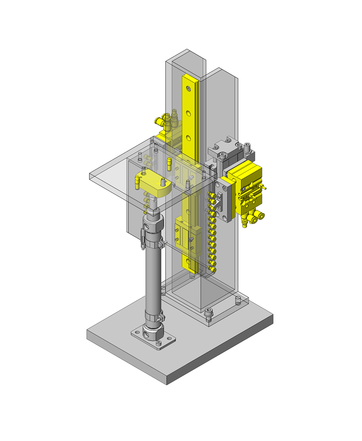
Cylinder-driven stepped feed
Related Category
- * Unit assembly CAD data consists of some sub-assemblies.
Each sub-assembly unit can be used as it is or can be edited.
Application Overview
Purpose
- Purpose
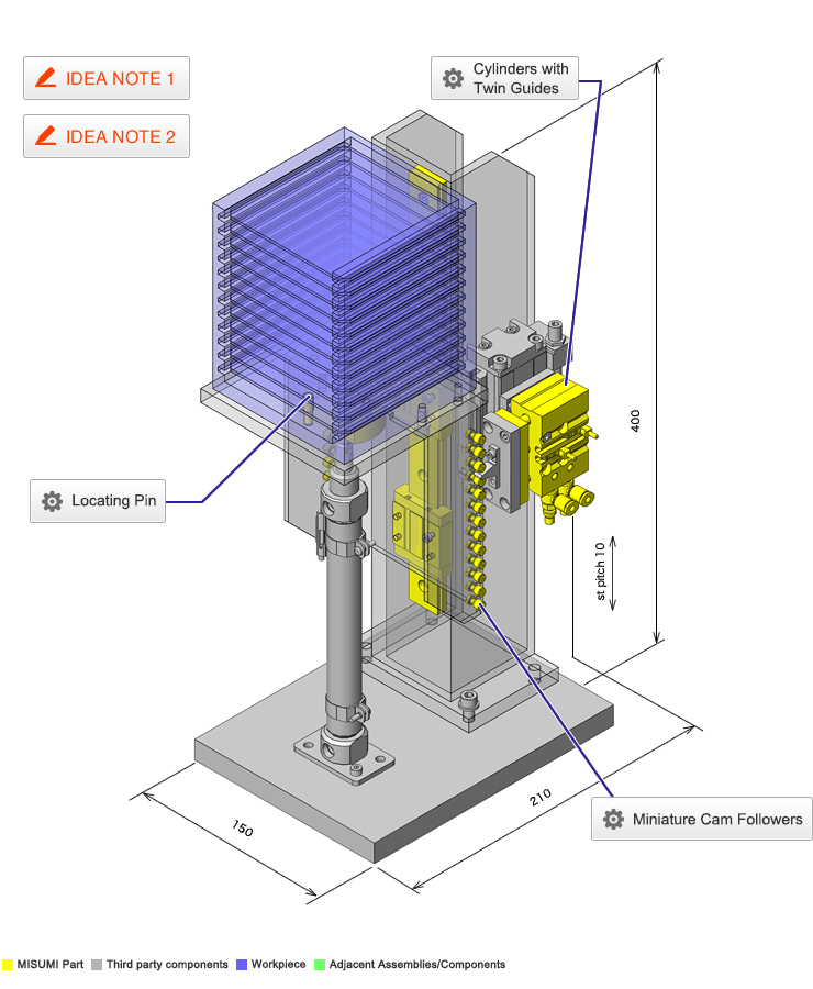
- Performing pitch feed to a position for loading and unloading the workpiece stocker.
- Operation
- (1) Balancer cylinder descends to lower end, pitch feed cylinder descends, while stopper and feed pin cylinders are in retracted position.
(2) Stopper pin cylinder extends.
(3) Feed pin extends while stopper pin cylinder returns.
(4) Pitch feed cylinder ascends.
(5) Stopper pin extends and feed pin cylinder returns.
(6) Pitch feed cylinder descends, repeats (3) to (6) 12 times. (workpiece loading onto stacker)
(7) The balancer cylinder is at the upper end.
(8) Stopper pin returns.
(9) Returns to balancer cylinder lower end (unloading from stocker) (2).
* For the roles of the cylinders, refer to IDEA NOTE 1.
- (1) Balancer cylinder descends to lower end, pitch feed cylinder descends, while stopper and feed pin cylinders are in retracted position.
Target workpiece
- Shape: thin plate workpiece
- Size: W100 x D100 x t2.0 mm
- Weight: 0.03 kg
- Stocker (capable of mounting 12 thin plate workpieces)
- Size: W110 x D110 x H134 mm
Weight: 0.6 kg
Design Specifications
Operating Conditions or Design Requirements
- Ascending feed pitch: 10 mm
- Outer dimensions: W150 x D210 x H400 mm
Selection Criteria for Main Components
- Cam followers are used for position, retention/feed of the stacker. They are arranged at the same pitch as the stacker pitch.
- Select pitch feed cylinder to have same stroke as the stacker pitch.
- For the cylinders for stopper and push pin movement, select a stroke that allows the pin to escape.
Design Evaluation
Verification of main components
- Whether the selected cylinder is appropriate for the workpiece load is verified.
- Vertical feed Cylinder
- Conditional value: operating air pressure 0.5 (MPa), efficiency: 0.8
- Vertical feed cylinder thrust: 113 N
- Vertical feed cylinder thrust = cylinder thrust x efficiency = 113 x 0.8 = 90.4 N
Balancer Cylinder - Conditional value: operating air pressure 0.1 (MPa), efficiency: 0.8
- Cylinder theoretical thrust: 31 N
- Balancer cylinder thrust = cylinder thrust x efficiency = 31 x 0.8 = 24.8 N
Load factor - Conditional value: workpiece weight 0.03 (kg), stacker weight 0.6 (kg), weight of parts included in lift unit 1.8 (kg), number of workpieces 12
- From load = (workpiece weight + stacker weight + lift unit weight) x 9.8,
Load = (0.03 (kg) x 12 + 0.6 (kg) + 1.8 (kg)) x 9.8 = 27 N - From load factor (%) = (load/cylinder thrust) x 100,
Load factor = (27/ (90.4 + 24.8)) x 100 = 23.4(%) < 50 (%)
⇒Selected cylinder meet design requirements.
Other Design Consideration
- The balance cylinder of this mechanism is structured with an air regulator to prevent load from being applied to the stepped feed cylinder.
- By utilizing a cylinder with a stopper (an external stopper can also be used) as the vertical feed cylinder, fine adjustment is possible and a repeatability of ±0.05 mm is achieved.
Explore Similar Application Examples
Page
-
/
-


