Cam Followers
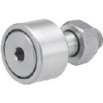
| Product name | Cam Followers/Hex Hole/Flat Type/No Seal |
| Part number | CFFAS6-16 |
* Orange colored cells in the table below indicate the part numbers used in this example.
Selection criteria
Centering is achieved, even if with some misalignment, when cam follower hits somewhere in the range of inclined part of V Groove.
Back to page top
Available sizes
■Cam Followers - Hex Hole, No Seal, Flat Type
| Purpose | Main Body | Nut |
| Material | Seal | Material | Surface Treatment |
| N/A | Yes |
| General | EN 1.3505 Equiv. | ○ | ○ | EN 1.1191 Equiv. | Black Oxide |
| EN 1.4125 Equiv. | ○ | ○ | EN 1.4301 Equiv. | - |
| Low particle generation | - | ○ |
■Sizes and Dimensions
| Stud Dia. | Thread Dia. x Pitch | Outer Ring Dia. | Outer Ring Width | Overall Length |
| Ø3 | M3 x 0.5 | Ø10 | 7 | 17 |
| Ø4 | M4 x 0.7 | Ø12 | 8 | 20 |
| Ø5 | M5 x 0.8 | Ø13 | 9 | 23 |
| Ø6 | M6 x 1.0 | Ø16 | 11 | 28 |
| Ø8 | M8 x 1.25 | Ø19 | 11 | 32 |
| Ø10 | M10 x 1.25 | Ø22 | 12 | 36 |
| Ø26 |
| Ø12 | M12 x 1.5 | Ø30 | 14 | 40 |
| Ø32 |
Back to page top
Accuracy Info
■Cam follower accuracy
Stud Dia. Tolerance: h7
Outer Ring Width Tolerance: 0/-0.12
Outer Race Dia. Tolerance:
| Outer Ring Dia. | Tolerance |
| Ø10 | 0/-0.008 |
| Ø12 |
| Ø13 |
| Ø16 |
| Ø19 | 0/-0.009 |
| Ø22 |
| Ø26 |
| Ø30 |
| Ø32 | 0/-0.011 |
Back to page top
Performance info.
Load capacity and rotation speed of cam follower
Stud Dia.
- Outer Ring Dia. | Basic Dynamic Load Rating C (kN) | Basic Static Load Rating Cor (kN) | Max. Allowable Load (kN) | Track Load Capacity (kN) | Rotational speed limit (rpm) |
| With Seal | Without Seal |
| Ø3-Ø10 | 1.47 | 1.18 | 0.36 | 1.37 | 32900 | 47000 |
| Ø4-Ø12 | 2.06 | 2.05 | 0.78 | 1.76 | 25900 | 37000 |
| Ø5-Ø13 | 3.14 | 2.77 | 1.42 | 2.25 | 20300 | 29000 |
| Ø6-Ø16 | 3.59 | 3.58 | 2.11 | 3.43 | 17500 | 25000 |
| Ø8-Ø19 | 4.17 | 4.65 | 4.73 | 4.02 | 14000 | 20000 |
| Ø10-Ø22 | 5.33 | 6.78 | 5.81 | 4.7 | 11900 | 17000 |
| Ø10-Ø26 | 5.49 |
| Ø12-Ø30 | 7.87 | 9.79 | 9.37 | 7.06 | 9800 | 14000 |
| Ø12-Ø32 | 7.45 |
Back to page top
Oil Free Bushings I.D. F7
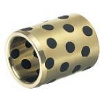
| Product name | Oil Free Bushings/Copper Alloy/Standard/I.D. F7/O.D. m6 |
| Part number | MPBZ15-15 |
| Features | The most standard type in the Copper Alloy series. |
* Orange colored cells in the table below indicate the part numbers used in this example.
Selection criteria
Provides high friction resistance in the environment where oil film formation is discouraged by reciprocating motions or frequent starts and stops, without lubrication.
Back to page top
Available sizes
■Oil Free Bushings I.D. F7 - Copper Alloy
Material: High Tensile Brass Alloy, Solid Lubricant Embedded
■Sizes and Dimensions
| I.D.(mm) | Overall Length | O.D. |
| 8 | 9 | 10 | 12 | 15 | 16 | 19 | 20 | 25 | 30 | 35 | 40 | 50 | 60 | 70 | 80 | 100 |
| 5 | ○ | ○ | ○ | ○ | ○ | - | - | - | - | - | - | - | - | - | - | - | - | 9 |
| 6 | ○ | ○ | ○ | ○ | ○ | ○ | ○ | ○ | - | - | - | - | - | - | - | - | - | 10 |
| 8 | ○ | ○ | ○ | ○ | ○ | ○ | ○ | ○ | ○ | - | - | - | - | - | - | - | - | 12 |
| 10 | ○ | ○ | ○ | ○ | ○ | ○ | ○ | ○ | ○ | ○ | - | - | - | - | - | - | - | 14 |
| 12 | ○ | ○ | ○ | ○ | ○ | ○ | ○ | ○ | ○ | ○ | ○ | - | - | - | - | - | - | 18 |
| 13 | - | ○ | ○ | ○ | ○ | ○ | ○ | ○ | ○ | ○ | ○ | - | - | - | - | - | - | 19 |
| 15 | - | ○ | ○ | ○ | ○ | ○ | ○ | ○ | ○ | ○ | ○ | ○ | - | - | - | - | - | 21 |
| 16 | - | ○ | ○ | ○ | ○ | ○ | ○ | ○ | ○ | ○ | ○ | ○ | - | - | - | - | - | 22 |
| 18 | - | ○ | ○ | ○ | ○ | ○ | ○ | ○ | ○ | ○ | ○ | ○ | - | - | - | - | - | 24 |
| 20 | - | ○ | ○ | ○ | ○ | ○ | ○ | ○ | ○ | ○ | ○ | ○ | ○ | ○ | - | - | - | 28 |
| 20A | - | ○ | ○ | ○ | ○ | ○ | ○ | ○ | ○ | ○ | ○ | ○ | ○ | - | - | - | - | 30 |
| 25 | - | - | - | ○ | ○ | ○ | ○ | ○ | ○ | ○ | ○ | ○ | ○ | ○ | - | - | - | 33 |
| 25A | - | - | - | ○ | ○ | ○ | ○ | ○ | ○ | ○ | ○ | ○ | ○ | ○ | - | - | - | 35 |
| 30 | - | - | - | ○ | ○ | ○ | ○ | ○ | ○ | ○ | ○ | ○ | ○ | ○ | ○ | - | - | 38 |
| 35 | - | - | - | - | - | - | - | ○ | ○ | ○ | ○ | ○ | ○ | ○ | ○ | - | - | 44 |
| 40 | - | - | - | - | - | - | - | ○ | ○ | ○ | ○ | ○ | ○ | ○ | ○ | ○ | - | 50 |
| 50 | - | - | - | - | - | - | - | - | - | ○ | ○ | ○ | ○ | ○ | ○ | ○ | - | 62 |
| 60 | - | - | - | - | - | - | - | - | - | - | - | - | ○ | ○ | ○ | ○ | - | 75 |
| 80 | - | - | - | - | - | - | - | - | - | - | - | - | - | ○ | ○ | ○ | - | 96 |
| 100 | - | - | - | - | - | - | - | - | - | - | - | - | - | - | - | ○ | ○ | 120 |
Back to page top
Accuracy Info
■Accuracy of Oil Free Bushings (Copper Alloy Straight Standard Type)
| I.D.(mm) | I.D. Tolerance (F7) | O.D. | O.D. Tolerance (m6) |
|
| 5 | +0.022
+0.010 | 9 | +0.015
+0.006 |
| 6 | 10 |
| 8 | +0.028
+0.013 | 12 | +0.018
+0.007 |
| 10 | 14 |
| 12 | +0.034
+0.016 | 18 |
| 13 | 19 | +0.021
+0.008 |
| 15 | 21 |
| 16 | 22 |
| 18 | 24 |
| 20 | +0.041
+0.020 | 28 |
| 20A | 30 |
| 25 | 33 | +0.025
+0.009 |
| 25A | 35 |
| 30 | 38 |
| 35 | +0.050
+0.025 | 44 |
| 40 | 50 |
| 50 | 62 | +0.030
+0.011 |
| 60 | +0.060
+0.030 | 75 |
| 80 | 96 | +0.035
+0.013 |
| 100 | +0.071
+0.036 | 120 |
Back to page top
Performance info.
■Load Information of Oil Free Bushings (Copper Alloy Straight Standard Type)
| Regular | Non-lubricated |
| Maximum Allowable Load | 29.0N/mm² |
| Maximum Allowable Velocity | 60m/min | 30m/min |
Back to page top
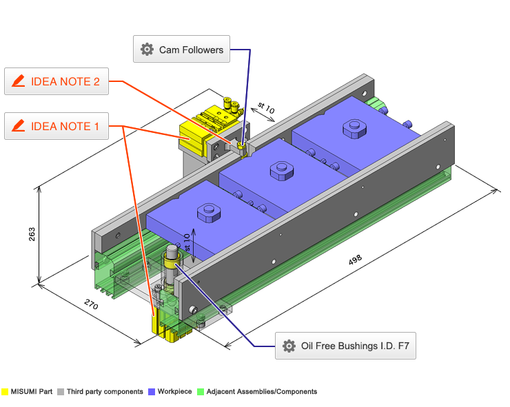
IDEA NOTE A cylinder is used to drive the stopper/blocker.
Due to the compact size of the cylinder, it can be used in a tight space.
IDEA NOTE Blocking: V groove + cam follower
Blocking is possible - even with a slight displacement - if the cam follower makes contact within the range of the oblique portion of the V groove.


