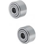
Roller Followers
| Product name | Roller Followers/Solid |
| Part number | NARTUC5 |
* Orange colored cells in the table below indicate the part numbers used in this example.
Selection criteria
Selecting the needle structure type that is hard to separate, for the concern of possible excessive load applied at clamp timing.
Back to page top
Available sizes
■Roller Followers - Solid
| Grease | No Seal | With Seal | Material |
| Crowned | Flat Type | Crowned | Flat Type |
| General | ○ | ○ | ○ | ○ | EN 1.3505 Equiv. |
| ○ | - | ○ | ○ | EN 1.4125 Equiv. |
| Low Rebound | - | - | ○ | - |
■Sizes and Dimensions
No Seal
O.D.
(mm) | I.D.
(mm) | Thickness(mm) |
|
| 16 | 5 | 11 |
| 19 | 6 |
| 24 | 8 | 14 |
| 30 | 10 |
| 32 | 12 |
With Seal
O.D.
(mm) | I.D.
(mm) | Thickness(mm) |
|
| 16 | 5 | 11 |
| 19 | 6 |
| 24 | 8 | 14 |
| 30 | 10 |
| 32 | 12 |
| 35 | 15 | 18.0 |
| 40 | 17 | 20.0 |
| 47 | 20 | 24.0 |
Back to page top
Accuracy Info
■Accuracy Information of Roller Followers
- Shaft Dia. Tolerance:
- 0
-0.008(mm)
- Roller Dia. Tolerance:
- 0
-0.005(mm)
Back to page top
Performance info.
■Speeds・Loads (Load info.) of roller followers
No Seal
I.D.
- O.D. | Basic Dynamic Load Rating
C (kN) | Basic Static Load Rating
Cor (kN) | Track Load
Capacity (kN) | Max. Rotational Speed (rpm) |
|
| Crowned | Flat
Type | Crowned | Flat
Type | Crowned | Flat
Type |
| Ø5-Ø16 | 2.84 | 6.46 | 2.65 | 7.81 | 1.08 | 25000 | 10500 |
| Ø6-Ø19 | 3.33 | 7.58 | 3.35 | 10.2 | 1.37 | 20000 | 8700 |
| Ø8-Ø24 | 5.68 | 11.7 | 5.89 | 15.6 | 1.86 | 17000 | 7000 |
| Ø10-Ø30 | 7.94 | 15.8 | 7.59 | 18.5 | 2.45 | 15000 | 5700 |
| Ø12-Ø32 | 8.53 | 17.0 | 8.44 | 21.0 | 2.74 | 13000 | 5200 |
With Seal
I.D.
- O.D. | Basic Dynamic Load Rating
C (kN) | Basic Static Load Rating
Cor (kN) | Track Load
Capacity (kN) | Max. Rotational Speed (rpm) |
|
| Crowned | Flat
Type | Crowned
Type | Flat
Type | Crowned
Type | Flat
Type |
| Ø5-Ø16 | 2.84 | 6.46 | 2.65 | 7.81 | 1.08 | 10000 | 4200 |
| Ø6-Ø19 | 3.33 | 7.58 | 3.35 | 10.2 | 1.37 | 8000 | 3480 |
| Ø8-Ø24 | 5.68 | 11.7 | 5.89 | 15.6 | 1.86 | 6800 | 2800 |
| Ø10-Ø30 | 7.94 | 15.8 | 7.59 | 18.5 | 2.45 | 6000 | 2280 |
| Ø12-Ø32 | 8.53 | 17.0 | 8.44 | 21.0 | 2.74 | 5200 | 2080 |
| Ø15-Ø35 | 13.7 | 25.3 | 16.4 | 36.9 | 3.14 | 4000 | 1720 |
| Ø17-Ø40 | 17.4 | 32.0 | 19.3 | 46.6 | 3.72 | 3800 | 1560 |
| Ø20-Ø47 | 22.9 | 41.7 | 30.6 | 67.7 | 7.15 | 3200 | 1360 |
Back to page top
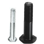
Roller Follower Pins Threaded
| Product name | Roller Follower Pins/Threaded |
| Part number | FSRFN5-25-F6 |
* Orange colored cells in the table below indicate the part numbers used in this example.
Selection criteria
It is easy to install because one side has a head.
Back to page top
Available sizes
■Roller Follower Pins (Threaded)
| Material | Surface Treatment |
| EN 1.1191 Equiv. | Black Oxide |
| EN 1.4301 Equiv. | - |
■Sizes and Dimensions
Pin Dia.
(mm) | Pin Length
(mm) | Thread Length
(mm) |
|
| 5 | 20, 25, 30 | 14 |
| 6 | 30, 32, 34, 36 |
| 8 | 30, 32, 34, 36, 38 | 16 |
| 10 | 36, 38, 42 | 19 |
| 12 | 38, 42, 46 | 22 |
| 15 | 38, 42, 46, 50 | 25 |
| 17 | 28 |
| 20 | 38, 42, 46, 50, 54 | 31 |
Back to page top
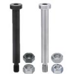
Hinge Pin
| Product name | Precision Pivot Pins/Flanged/Hex Socket Head/Threaded with Lock Nut |
| Part number | SCLBR4-20 |
* Orange colored cells in the table below indicate the part numbers used in this example.
Selection criteria
It enables one to obtain the components that normally require large amount of machining such as flange by ready-made products.
Back to page top
Available sizes
■Hinge Pins - Flanged, Hex Socket Head, Threaded with Lock Nut
| Material | Hardness | Surface Treatment | Included nut material |
| Standard nut | U nut |
| EN 1.1191 Equiv. | - | Black Oxide | JIS-SWRCH | EN 1.0038 Equiv. |
| 40 ~ 45HRC |
| - | Electroless Nickel Plating | EN 1.4301 Equiv. | EN 1.4301 Equiv. |
| 40 ~ 45HRC |
| Plating hardness 750HV - | Hard Chrome Plating
Plating Thickness 3 μm or more | JIS-SWRM | EN 1.0038 Equiv. |
| EN 1.4301 Equiv. | - | - | EN 1.4301 Equiv. | EN 1.4301 Equiv. |
| EN 1.4125 Equiv. | 45 ~ 50HRC |
45 ~ 50HRC
Plating hardness 750HV - | Hard Chrome Plating
Plating Thickness 3 μm or more |
■Sizes and Dimensions
| Pin Dia. | Pin section length
(Configurable in 0.1 mm increment) | Head O.D. | Head Height | Thread Length | Thread Dia. X Pitch |
| Ø4 | 10.0- 50.0 | Ø7 | 5 | 6 | M3 x 0.5 |
| Ø5 | 10.0- 60.0 | Ø9 | M4 x 0.7 |
| Ø6 | 10.0-100.0 | Ø10 | 9 | M5 x 0.8 |
| Ø8 | 10.0-100.0 | Ø13 | M6 x 1.0 |
| Ø10 | Ø16 | 12 | M8 x 1.25 |
| Ø12 | 10.0-200.0 | Ø18 | 16 | M10 x 1.5 |
| Ø13 | 20.0-200.0 | Ø24 | 18 | M12 x 1.75 |
| Ø14 |
| Ø15 |
| Ø16 | 20.0-200.0 |
| Ø17 |
| Ø18 | 24 |
| Ø20 | Ø27 | M16 x 2.0 |
| Ø22 | 20.0-200.0 |
| Ø25 | Ø30 |
Back to page top
Accuracy Info
■Pivot pin, Flanged with Hex socket, Tapped: Pin Dia. tolerance (g6)
| Pin Dia. | Tolerance |
| Ø4-Ø6 | -0.004
-0.012 |
|
| Ø8 ・ Ø10 | -0.005
-0.014 |
|
| Ø12-Ø18 | -0.006
-0.017 |
|
| Ø20 ・ Ø22 ・ Ø25 | -0.007
-0.020 |
|
Back to page top
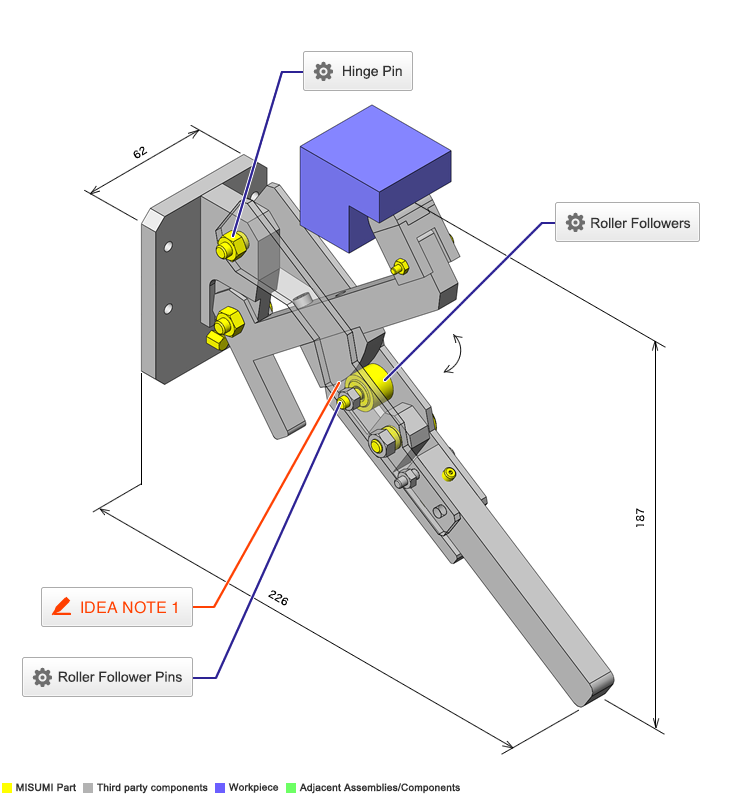
IDEA NOTE Cam follower wedge
Cam follower and wedge are used to allow for easy rolling motion and to minimise dust generation.


