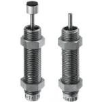
Shock Absorber
| Product name | Shock Absorbers/Preset Dampening |
| Model number | MAKC0805B |
* Orange colored cells in the table below indicate the part numbers that were actually used in this app. example.
Selection criteria
To smooth out shock and absorb energy at end stroke.
Back to page top
Available sizes
■Shock Absorbers
| Type | Thread Dia. - Pitch | Stroke | Body material | Surface treatment | Speed | Overall length |
| With Cap | Without Cap |
With Cap
Without Cap | M4 - 0.5 | 4 | EN 1.4305 Equiv. | - | Low Speed | 32.6 | 28.6 |
| M6 - 0.75 | Low Speed | 33 | 29 |
| M8 - 0.75 | 5 | EN CW614N Equiv. | Electroless
Nickel
Plating | Low Speed | 37 | 32 |
| M10 - 1 | Free Cutting Steel | Low Speed | 39 |
| 8 | Low Speed | 53 | 46 |
| Low Speed | 55 | 48 |
| Medium Speed |
| High Speed |
Back to page top
Selection steps
■Shock Absorbers Selection Steps
1. Calculate the inertia energy (E1)
Calculate the energy based on the collision material mass (m) , collision velocity (V) , moment of inertia (I) , and collision angle velocity (u) , according to the selection calculation example.
↓
2. Temporarily select the absorber stroke
Determine the temporary stroke (S') according to Fig.1.
↓
3. Calculate the addition energy (E2')
Verify the existence of thrust force (F) and calculate the addition energy according to the selection calculation example.
↓
4. Calculate the total energy
Calculate the total energy by adding inertia energy (E1) and addition energy (E2') together.
↓
Fig.1 Determine the temporary stroke (S') based on the inertia energy (E1) (adjustable / fixed type)
5. Check the equivalent mass
Calculate the equivalent mass according to the selection calculation example to check if it is less than or equal to the maximum equivalent mass (me') shown in the catalog.
↓
6. Select the absorption property structure from the energy ratio.
Temporarily select the orifice type according to Fig.2.
↓
7. Check the max. absorption energy per minute
Calculate the energy per minute (ET) based on the operating cycle (times/min) and the total energy to confirm that it is within the operating range.
Fig.2 Select the orifice type based on the energy ratio (addition energy (E2') / inertia energy (E1))
Back to page top
Performance info.
■Shock Absorber Properties (Fixed)
| Thread Dia. - Pitch | Stroke | Speed | Max. Absorption Energy | Max. Equiv.
Mass (kg) |
| Each Time (J) | Per Minute (J) |
| M4 - 0.5 | 4 | A | 0.1 | 4.5 | 1 |
| B | 0.3 | 13.5 | 3 |
| M6 - 0.75 | A | 0.1 | 4.5 | 1 |
| B | 0.3 | 13.5 | 2 |
| L | 0.5 | 22.5 | 3 |
| M8 - 0.75 | 5 | A | 0.39 | 17.6 |
| B | 0.68 | 22.5 | 5 |
| M10 - 1 | A | 41.1 |
| B | 0.98 | 8 |
| 8 | A | 58.8 | 7 |
| B | 1.47 | 10 |
| L | 2.94 | 20 |
| M | 9 |
| H | 2.5 |
| Speed Type | Impact Speed Range |
| Low Speed | A | 0.3 - 1m/s |
| B |
| L |
| Medium Speed | M | 0.3 - 2m/s |
| High Speed | H | 0.3 - 3m/s |
Back to page top
Technical calculations
- ■Shock Absorber Energy Calculations
- Selection example: Horizontal collision with air cylinder thrust
-

- m = 30kg
- V = 0.6m/s
- N = 20 times/min
- Air Cylinder
- I.D.: Ø40, Operating pressure: 0.5 Mpa
-
●Inertia energy E1 (J)
-
●Temporary stroke S' (mm)
S' = 15 mm according to Fig.1
(See the shock absorber selection steps for Fig.1)
-
●Addition energy E2' (J)
Cylinder thrust is F = 628.4N
E2' = F x S' = 628.4 x 0.015 = 9.4 J
-
●Total energy E' (J)
E' = E1 + E2' = 5.4 + 9.4 = 14.8J
-
Equiv. mass me' (kg)
-
Temporary selection
Select the adjustable type
Select the medium speed M from the collision velocity
Select MAC2016M from E' and me' (stroke S = 16mm)
-
Re-calculate
E2 = F x S = 10.1J
E = E1 + E2 = 15.5J
Energy per minute ET
ET = E x N = 15.5J x 20 = 310J/min
Back to page top
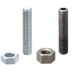
Adjusting Stopper Screw
| Product name | Adjusting Stopper Screws/Hexagon Socket/L Configurable/Fine Thread |
| Model number | ANB6-30 |
* Orange colored cells in the table below indicate the part numbers that were actually used in this app. example.
Selection criteria
Forward End Position Fine Adjustment
Back to page top
Risk info.
Contact Surface Abrasion
Back to page top
Available sizes
■Adjusting Stopper Screws- Hexagon Socket, L Configurable, Fine Thread
Screw
Type | Material | Hardness
(Tip) | Surface treatment | Accessory (Nut x 1pc.) |
| Material | Surface treatment |
Fine Thread
・
Coarse Thread | EN 1.1191 Equiv. | 45 ~ 50HRC | Electroless
Nickel Plating | EN 1.0038 Equiv. | Trivalent
Chromate |
| Trivalent Chromate |
| EN 1.7220 Equiv. | 50HRC ~ |
| EN 1.4301 Equiv. | - | - | EN 1.4301 Equiv. | - |
| EN 1.4031 Equiv. | 45HRC ~ | - |
■Size Specification
| Thread Diameter x Pitch | Overall length
(in the increment of 5mm) |
| Fine Thread | Coarse Thread |
| M3 x 0.35 | M3 x 0.5 | 10 ~ 40 |
| M4 x 0.5 | M4 x 0.7 | 10 ~ 60 |
| M5 x 0.5 | M5 x 0.8 | 10 ~ 60 |
| M6 x 0.75 | M6 x 1.0 | 15 ~ 60 |
| M8 x 0.75 | M8 x 1.25 | 20 ~ 60 |
| M10 x 1.0 | M10 x 1.5 | 25 ~ 100 |
| M12 x 1.0 | M12 x 1.75 | 30 ~ 100 |
| M16 x 1.5 | M16 x 2.0 | 40 ~ 100 |
| M20 x 1.5 | M20 x 2.5 | 45 ~ 120 |
* Selectable size will differ depending on materials.
* For details, please see products page.
Back to page top
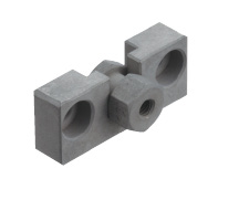
Floating Joint
| Product name | Floating Joints/Tapped Cylinder Connector and Holder Set |
| Model number | FJRHA5-0.8 |
* Orange colored cells in the table below indicate the part numbers that were actually used in this app. example.
Selection criteria
A more rigid type was selected to support the load applied to cylinder.
Back to page top
Available sizes
■Floating Joints - Quick Connection Type - Cylinder Connector and Holder Set
| Part No. | Part name | Material |
| (1) | Stud | EN 1.4301 Equiv. |
| (2) | Nut | EN 1.0038 Equiv. |
| (3) | Case | EN CW614N Equiv. |
| (4) | Ball Holder |
| (5) | Ball Joiner |
| (6) | Socket |
| (7) | Rod Tip Nut | JIS-SWCH8R |
| Screw Diameter - Pitch | Stud Length | Screw Depth | Overall length |
| M4 - 0.7 | 10 | 4.5 | 26 |
| M5 - 0.8 | 12.5 | 6 | 33.5 |
| M6 - 1.0 | 15.5 | 36.5 |
Back to page top
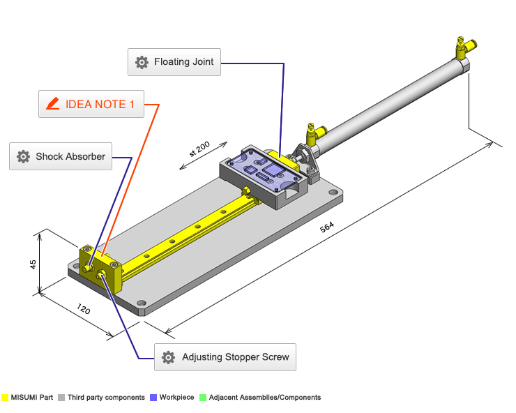
IDEA NOTE Stopper and shock absorber are mounted on the same block.
Standard MISUMI block for mounting both shock absorber and stopper for more compact design and reduction in number of parts.


