Cam Followers
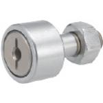
Product name | Cam Followers/Flat Type/No Seal |
Part number | CFFR5-13 |
* Orange colored cells in the table below indicate the part numbers used in this example.
Selection criteria
Suitable as a joint part of link mechanism.
Back to page top.
Available sizes
■Cam Followers - Flat Type - No Seal
Purpose | Main Body | Nut |
Material | Seal | Material | Surface Treatment |
N/A | Yes |
General | EN 1.3505 Equiv. | ○ | ○ | EN 1.1191 Equiv. | Black Oxide |
EN 1.4125 Equiv. | ○ | ○ | EN 1.4301 Equiv. | - |
Low particle generation | - | ○ |
■Sizes and Dimensions.
Stud Dia. | Thread Dia. x Pitch | Outer Ring Dia. | Outer race width | Overall Length |
Ø5 | M5 x 0.8 | Ø13 | 9 | 23 |
Ø6 | M6 x 1.0 | Ø16 | 11 | 28 |
Ø8 | M8 x 1.25 | Ø19 | 11 | 32 |
Ø10 | M10 x 1.25 | Ø22 | 12 | 36 |
Ø26 |
Ø12 | M12 x 1.5 | Ø30 | 14 | 40 |
Ø32 |
Ø16 | M16 x 1.5 | Ø35 | 18 | 52 |
Ø18 | M18 x 1.5 | Ø40 | 20 | 58 |
Ø20 | M20 x 1.5 | Ø52 | 22 | 66 |
Back to page top
Accuracy Info
■Cam follower accuracy
Stud Dia. Tolerance: h7
Outer ring Width Tolerance: 0/-0.12.
Outer ring DIA. Tolerance:
Outer Ring Dia. | Tolerance |
Ø13 | 0/-0.008 |
Ø16 |
Ø19 | 0/-0.009 |
Ø22 |
Ø26 |
Ø30 |
Ø32 | 0/-0.011 |
Ø35 |
Ø40 |
Ø52 | 0/-0.013 |
Back to page top
Performance info
■Load capacity and rotation speed of cam follower
Stud Dia. -Outer Ring Dia. | Basic Dynamic Load Rating C (kN) | Basic Static Load Rating Cor (kN) | Max. Allowable Load (kN) | Track Load Capacity (kN) | Rotational speed limit (rpm) |
With Seal | Without Seal |
Ø3-Ø10 | 1.47 | 1.18 | 0.36 | 1.37 | 32900 | 47000 |
Ø4-Ø12 | 2.06 | 2.05 | 0.78 | 1.76 | 25900 | 37000 |
Ø5-Ø13 | 3.14 | 2.77 | 1.42 | 2.25 | 20300 | 29000 |
Ø6-Ø16 | 3.59 | 3.58 | 2.11 | 3.43 | 17500 | 25000 |
Ø8-Ø19 | 4.17 | 4.65 | 4.73 | 4.02 | 14000 | 20000 |
Ø10-Ø22 | 5.33 | 6.78 | 5.81 | 4.7 | 11900 | 17000 |
Ø10-Ø26 | 5.49 |
Ø12-Ø30 | 7.87 | 9.79 | 9.37 | 7.06 | 9800 | 14000 |
Ø12-Ø32 | 7.45 |
Ø16-Ø35 | 12 | 18.3 | 17.3 | 11.2 | 7000 | 10000 |
Ø18-Ø40 | 14.7 | 25.2 | 26.1 | 14.4 | 5950 | 8500 |
Ø20-Ø52 | 20.7 | 34.8 | 32.1 | 23.2 | 4900 | 7000 |
Back to page top
Shaft Collar
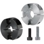
Product name | Shaft Collars/With Counterbored Holes |
Part number | PSCSG10-15 |
* Orange colored cells in the table below indicate the part numbers used in this example.
Selection criteria
Select the counterbored type to maintain the workability of the mounting screws when adjusting the position of shaft clamps.
Back to page top
Available sizes
■Shaft Collars - With Counterbored Holes
Material | Surface Treatment |
EN 1.1191 Equiv. | Black Oxide |
Electroless Nickel Plating |
EN 1.4301 Equiv. | - |
■Sizes and Dimensions.
Shaft Bore I.D. | Overall Thickness (width) | O.D. | Fastening Screw DIA. (Coarse) | For Screw Hole |
Pitch | Hole Dia. |
Ø6 | 8 | Ø24 | M3 | 15 | Ø3.5 |
10 | M4 |
Ø8 | 8 | Ø25 | M3 | 17 |
10 | Ø28 | M4 | 18 | Ø4.5 |
Ø10 | Ø33 | 22 | Ø5.5 |
12 | M5 |
15 | Ø36 | M6 | 23 | Ø6.6 |
Ø12 | 10 | Ø35 | M4 | 24 | Ø5.5 |
12 | M5 |
15 | Ø38 | M6 | 25 | Ø6.6 |
Ø13 | 10 | Ø33 | M4 | 23 | Ø4.5 |
12 | Ø36 | M5 | 25 | Ø5.5 |
15 | M6 |
Ø15 | 12 | Ø38 | M5 | 27 |
15 | Ø40 | M6 | 28 | Ø6.6 |
Ø16 | 10 | Ø36 | M5 | 26 | Ø4.5 |
12 | Ø38 | 28 | Ø5.5 |
15 | Ø42 | M6 | 29 | Ø6.6 |
Ø20 | 12 | M5 | 32 | Ø5.5 |
15 | Ø45 | M6 | 33 | Ø6.6 |
20 |
Ø25 | 12 | Ø48 | M5 | 37 | Ø5.5 |
15 | Ø50 | M6 | 38 | Ø6.6 |
Ø30 | Ø55 | 43 |
Ø35 | Ø60 | 48 |
Ø40 | 18 | Ø78 | M8 | 60 | Ø9 |
Ø50 | 22 | Ø88 | M10 | 71 | Ø11 |
Back to page top
Accuracy Info.
■Accuracy of shaft collars.
I.D. Tolerance | +0.05/+0.01 |
O.D. Tolerance | ±0.1 |
Overall Thickness (width) Tolerance | ±0.1 |
Back to page top
Knuckle Joints
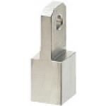
Product name | Knuckle Joints/Tapped/Selectable |
Part number | NJTB6-1.0-B4 |
Features | Knuckle Joints equipped with Rotation Stopper and compatible with M3~M18 screws regardless of Convex Type or Concave Type. |
* Orange colored cells in the table below indicate the part numbers used in this example.
Selection criteria
Suitable as a oscillating part of cylinder link mechanism.
Back to page top
Available sizes
■Knuckle Joints - Tapped, Selectable
Material | Surface Treatment | Convex Shaped | Concave Shaped |
EN 1.1191 Equiv. | Black Oxide | ○ | ○ |
Electroless Nickel Plating | - | ○ |
EN 1.4301 Equiv. | - | ○ | ○ |
■Sizes and Dimensions.
Thread Dia. x Pitch | Joint Parts | Hole Dia. | Overall Length | Overall thickness | Width |
Thickness (width) |
M3 x 0.5 | 4 ・ 5 | Ø4 | 20 | 10 | 10 |
M4 x 0.7 | 5 ・ 6 | Ø5 | 25 |
M5 x 0.8 | 12 | 12 |
M6 x 1.0 | 4 ・ 6 |
M8 x 1.0 | 5 ・ 8 | Ø8 | 35 | 16 | 16 |
M8 x 1.25 |
M10 x 1.25 | 6 ・ 10 | Ø10 | 20 | 20 |
M10 x 1.5 |
M12 x 1.25 | 8 ・ 10 | Ø12 | 40 | 22 | 22 |
M12 x 1.5 |
M14 x 1.5 | 10 ・ 12 | 50 | 25 | 25 |
M16 x 1.5 | 55 |
M18 x 1.5 | 12 ・ 14 | 28 | 28 |
Back to page top
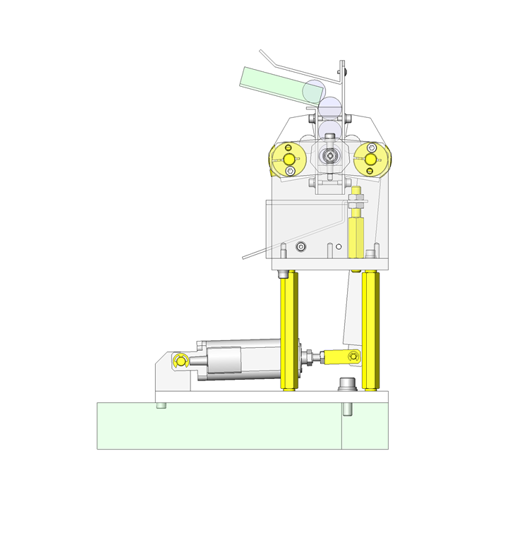
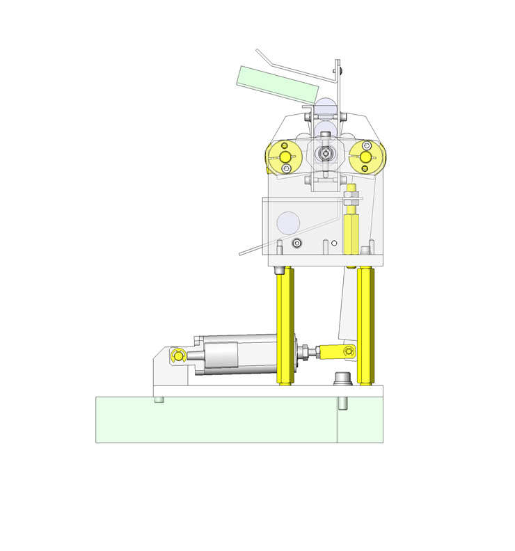
IDEA NOTE Separates cylindrical workpieces by means of a single actuator.
By setting the claw rotation center positions, claw opening amount and stopper position with ingenuity, separation action by a single actuator is made possible.
The claws rotate to release the lowermost workpiece and stop the next workpiece.
IDEA NOTE Reduces the vertical space required for installation.
Horizontal arrangement of electric cylinder and use of link for swiveling.
IDEA NOTE Tightening of link and rotary shaft
By tightening the rotary shaft using a shaft collar with tap, synchronization adjustment is facilitated.