- inCAD Library Home
- > No.000115 Chuck Mechanism
No.000115 Chuck Mechanism
26
26
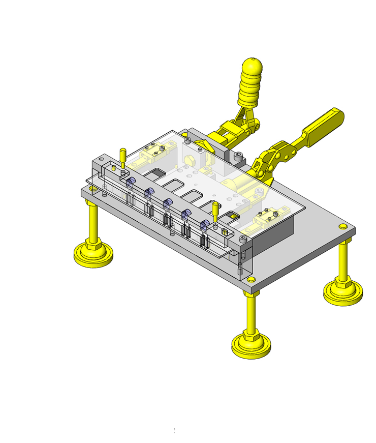
Chuck mechanism capable of correcting positional displacement.
Related Category
- * Unit assembly CAD data consists of some sub-assemblies.
Each sub-assembly unit can be used as it is or can be edited.
Application Overview
Purpose
- Chuck workpieces while correcting fine displacement.
- Springs are used to generate the necessary holding force. The claws of the chuck are adjustable to account for positional displacement.
Points for use
- Low precision workpiece chucking.
Target workpiece
- Shape: resin pin.
size: Ø10 x 45mm.
weight: 0.1kg.
Design Specifications
Operating Conditions or Design Requirements
- Assumed workpiece displacement amount: ±1.5mm.
- Spring gripping force: 23.1 to 54.6N.
- Outer dimensions: W86 x D117.5 x H58mm.
Selection Criteria for Main Components
- Springs that produce a gripping force of 2kg during chucking are selected.
Design Evaluation
Verification of main components
- Spring gripping force is verified below.
- Confirmation of gripping force of chucks.
- Conditional value: spring constant k = 10.5N/mm.
Spring free length: L0 = 15mm.
Minimum spring length caused by maximum displacement amount 1.5mm: L1 = 9.8mm.
Spring length when displacement amount is 0mm: L2 = 11.4mm.
Maximum spring length caused by maximum displacement amount 1.5 mm: L3 = 12.8mm.
- Maximum spring deflection amount caused by maximum displacement amount 1.5mm: X1 = L0 - L1 = 5.2mm.
Spring deflection amount when displacement amount is 0mm: X2 = 3.6mm.
Minimum spring deflection amount caused by maximum displacement amount 1.5mm: X3 = L0 - L3 = 2.2mm.
- Maximum chuck gripping force: F1 = k x X1 = 10.5 x 5.2 = 54.6N.
Chuck gripping force when there is no workpiece displacement: F2 = k x X2 = 10.5 x 3.6 = 37.8N.
Minimum chuck gripping force: F3 = k x X3 = 10.5 x 2.2 = 23.1N.
- Conditional value: spring constant k = 10.5N/mm.
Other Design Consideration
- The cam shape applies load to the spring during chucking and completely opens the claws from the workpiece during un-chucking.
Explore Similar Application Examples
Page
-
/
-


