
- inCAD Library Home
- > No.000031 High accuracy XY table unit
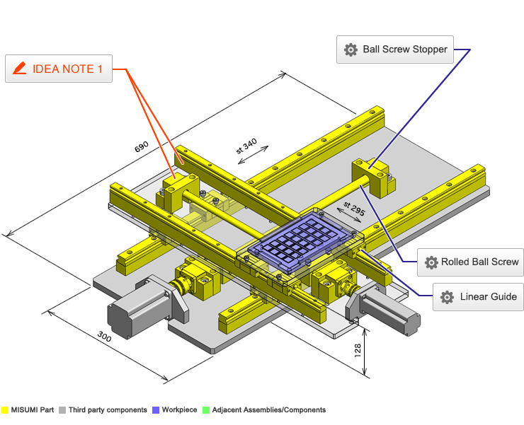
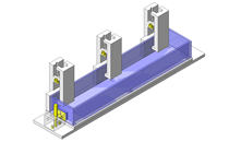
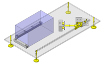
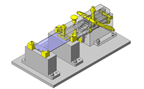
No.000031 High accuracy XY table unit
335
XY table with overrun protection
Related Category


Rolled Ball Screw
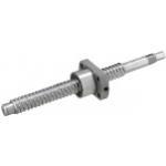
| Product name | Rolled Ball Screws/Compact Nut/Shaft Dia. 15/Lead 5/10 |
|---|---|
| Part number | BSS1505-500 |
| Features | Smallest Nut Outer Diameter |
Selection criteria
Suitable for med. accuracy linear motion drive.
Available sizes
■Precision Ball Screws
| Screw shaft | Nut | |||||
|---|---|---|---|---|---|---|
| Material | Hardness | Screw DIA.(mm) | Lead(mm) | Overall length(mm) | Material | Hardness |
| EN 1.7242 Equiv. | Carburized 58 ~ 62HRC | Ø8 | 2 | 100-210 | EN 1.7264 Equiv. | Carburized 58 ~ 62HRC |
| Ø10 | 2 | 100-315 | ||||
| 4150 Alloy Steel | Induction hardened 58 ~ 62HRC | 4 | 150-380 | |||
| 10 | 150-450 | |||||
| EN 1.7242 Equiv. | Carburized 58 ~ 62HRC | Ø12 | 2 | 150-445 | ||
| 4150 Alloy Steel | Induction hardened 58 ~ 62HRC | 4 | 150-400 | |||
| 5 | 150-450 | |||||
| 10 | 200-600 | |||||
| Ø15 | 5 | 150-1095 | ||||
| 10 | 200-1095 | |||||
| 20 | 230-1095 | |||||
| Ø20 | 5 | 200-1000 | ||||
| 10 | 250-1500 | |||||
| 20 | ||||||
| Ø25 | 5 | 300-995 | ||||
| 10 | 300-1500 | |||||
| 20 | ||||||
■Features of Compact nut
Compact nut O.D.
Suitable for limited space applications
Selection steps
■Ball screw selection steps
- Determine application conditions
- (Moving mass, feed rate, motion pattern, screw rotary speed, mounting orientation (horizontal or vertical), life, positioning accuracy)
↓
- Temporarily select ball screw specifications
- (Based on app. conditions, ball screw accuracy grade (C3~C10), screw shaft DIA., lead, screw shaft length are temporarily selected.)
↓
- Basic Safety Check
-
- ● Allowable axial load
- ● Allowable max. speed
- ● Life
↓
- Evaluate in accordance with the required performance
-
- ● Screw shaft rigidity
- ● Change in life due to temperature
Accuracy Info
■Ball screw accuracy

| Accuracy grade: C10 | (mm) |
| Screw shaft DIA. | Lead | Axial clearance | Twist direction | Nut pilot tolerance | (1) (2) | (3) | (4) (5) | (6) | (7) |
|---|---|---|---|---|---|---|---|---|---|
| Runout tolerance (Max.) | Runout tolerance (Max.) | Perpendicularity tolerance (Max.) | Perpendicularity tolerance (Max.) | Runout tolerance (Max.) | |||||
| Ø8 | 2 | 0.005 or less | Right | -0.007/-0.020 | 0.011 | 0.011 | 0.005 | 0.010 | 0.012 |
| Ø10 | 2 ・ 4 ・ 10 | ||||||||
| Ø12 | 2 ・ 4 ・ 5 ・ 10 | ||||||||
| Ø15 | 5 ・ 10 ・ 20 | -0.009/-0.025 | 0.012 | 0.012 | 0.011 | 0.015 | |||
| Ø20 | 5 ・ 10 ・ 20 | ||||||||
| Ø25 | 5 ・ 10 | 0.013 | 0.013 | 0.013 | 0.019 | ||||
| 20 | -0.010/-0.029 |
(mm)
| Screw shaft DIA. | (8) Runout tolerance (Max.) / Screw shaft length | |||||||||
|---|---|---|---|---|---|---|---|---|---|---|
| -125 | 126-200 | 201-315 | 316-400 | 401-500 | 501-630 | 631-800 | 801-1000 | 1001-1250 | 1251- | |
| Ø8 | 0.035 | 0.050 | 0.065 | - | - | - | - | - | - | - |
| Ø10 | 0.040 | 0.055 | 0.065 | 0.080 | 0.090 | |||||
| Ø12 | ||||||||||
| Ø15 | - | 0.045 | 0.055 | 0.060 | 0.075 | 0.090 | 0.120 | 0.150 | 0.190 | |
| Ø20 | ||||||||||
| Ø25 | - | 0.040 | 0.045 | 0.050 | 0.060 | 0.070 | 0.085 | 0.100 | 0.130 | |
Performance info.
■Ball screw load ratings
| Screw shaft DIA. | Lead | Basic load ratings | |
|---|---|---|---|
| C (Dynamic) kN | Co (Static) kN | ||
| Ø8 | 2 | 1.95 | 2.6 |
| Ø10 | 2 | 2.25 | 3.3 |
| 4 | 3.35 | 5.9 | |
| 10 | 2.2 | 3.5 | |
| Ø12 | 2 | 2.45 | 4.1 |
| 4 | 3.6 | 6.75 | |
| 5 | 5.95 | 9.8 | |
| 10 | 3.85 | 5.9 | |
| Ø15 | 5 | 6.9 | 12.5 |
| 10 ・ 20 | 4.4 | 7.9 | |
| Ø20 | 5 | 8.35 | 17.5 |
| 10 | 13.5 | 25.1 | |
| 20 | 9.2 | 16.2 | |
| Ø25 | 5 | 9.4 | 22.2 |
| 10 | 16.1 | 33.4 | |
| 20 | 10.4 | 20.1 | |
Technical calculations
■Ball screw life calculations
Ball screw life time is calculated by the following formula.

- C: Basic dynamic load rating (N)
- Pm: Average axial load (N)
- Nm: Average rotational speed (min-1)
- fw: Operation factor
- Steady operation without impact fw = 1.0 ~ 1.2
- Normal operation fw = 1.2 ~ 1.5
- Operation with impacts fw = 1.5 ~ 2.0
- Definition of basic dynamic load rating -
Basic dynamic load rating is an axial load applied on ball screws where a group of the same ball screws
are operated and 90% of the specimen will reach 1,000,000 (10^6) rotations without showing any flaking.
- About average axial load and average rotational speed. -
This needs to be calculated based on the motion pattern.
While it is difficult to accurately obtain load condition, etc, we do know that the ball screws operating life is inversely proportional to the third power of the load.
- Motion pattern example - (T1 + T2 + T3 = 100%)
| Motion pattern | Axial load | Rotational speed | Time proportion |
|---|---|---|---|
| A | P1N | N1min^-1 | t1% |
| B | P2N | N2min^-1 | t2% |
| C | P3N | N3min^-1 | t3% |


Ball Screw Stopper
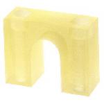
| Product name | Stopper for Ball Screws |
|---|---|
| Part number | BSTS12 |
Selection criteria
Urethane stopper for overrun protection
Available sizes
■Stopper for Ball Screws
(mm)
| Material | Hardness | Applicable ball screw DIA. | Stopper plate thickness | Ball screw shaft center height |
|---|---|---|---|---|
| Ether based polyurethane | Shore A90 | Ø8 | 15 | 17 |
| Ø10 | 18 | 22, 25 | ||
| Ø12 | 18 | 23, 25 | ||
| Ø15 | 20 | 26, 28, 30 | ||
| Ø20 | 20 | 30 | ||
| Ø25 | 20 | 35 |

Linear Guide
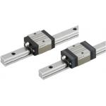
| Product name | Linear Guides for Medium Load |
|---|---|
| Part number | SV2R-MX24-520-WC |
| Features | Compliant with the industry standard specifications. |
Selection criteria
Standard block, Medium load, normal clearance linear guide
Available sizes
■Linear Guides for Medium Load
| Material | Hardness | Overall height(mm) | Rail length(mm) |
|---|---|---|---|
| Carbon steel | 58HRC ~ | 24 | 160-1480 |
| 28 | 220-1960 | ||
| 33 | 220-1960 |
Selection steps
■Linear guide selection steps
- Determine application conditions
- (Mass of moving body, Feed rate, Motion pattern, Life)
↓
- Selection of linear guide specifications
- (Temporarily select linear guide load type, overall height,
rail length based on the application condition)
↓
- Safety Check
-
- ●Load capacity
- ●Life
- ●Preload
Accuracy Info
■Preload and accuracy reference Standards

(μm)
| Dimension tolerance of H | ±100 | |
|---|---|---|
| Pair variation of H | 20 | |
| Dimension tolerance of W2 | ±100 | |
| Pair variation of W2 | H24 ・ 28 | 20 |
| H33 | 30 | |
(μm)
| Rail length | |||||||||
|---|---|---|---|---|---|---|---|---|---|
| -250 | 251-400 | 401-500 | 501-630 | 631-800 | 801-1000 | 1001-1250 | 1251-1600 | 1601-2000 | |
| Running Parallelism | 7 | 12 | 14 | 18 | 21 | 23 | 25 | 27 | 28.5 |
Performance info.
■Linear guide load ratings (For med. loads, Normal clearance, Standard grade)
| Overall height | Basic load rating | Allowable static moment | ||
|---|---|---|---|---|
| C (Dynamic) kN | C 0 (Static) kN | MA ・ MB N・m | Mc N・m | |
| 24 | 5.0 | 8.23 | 33 | 57 |
| 28 | 7.2 | 12.1 | 58 | 135 |
| 33 | 11.7 | 19.6 | 109 | 225 |

Technical calculations
■Linear guide life calculations
- ●Operating Life
- When a linear guide is loaded in linear reciprocating motion, scaly damage called flaking can appear. This is due to material fatigue because the stress works on the rolling elements and contact surfaces constantly. Total travel distance until the first flaking occurs is the life of the linear guide.
- ●Rated life
- Rated life is the total travel distance that 90% of same linear guides, under the same conditions, can reach with no occurrence of flaking damage. Rated life can be obtained from the Basic Dynamic Load Rating and the actual load applied on the linear blocks, as shown below.
-

- Load must be calculated before actually using a linear guide. To obtain load during linear reciprocating motion, it is necessary to consider vibration, impact during motion and the distribution status of the linear guides. The operating environment temperature also effects the life of these parts. when taking these conditions into considiration, the calculation will be:
-

- L: Rated life (km)
- fH: Hardness factor (see Fig-1)
- fT: Temperature factor (see Fig-2)
- fC: Contact factor (see Table-1)
- fW: Load factor (see Table-2)
- C: Basic dynamic load rating (N)
- P: Applicable load (N)
- ●Hardness Factor (fH)
-

For Linear Guide applications, sufficient hardness is required for ball contact shafts. Inappropriate hardness causes less allowable load, resulting in shorter life. Please correct the rated life according to the hardness factors.
- ●Temperature Factor (fT)
-

If the linear guide temperature exceeds 100°C, the linear guide and rail hardness decreases. This results in a lower allowable load and a shorter life when compared to an application at room temperature. Please correct the rated life according to the temperature factor.
*Please use linear guide under the allowable temperature shown on each product page.
- ●Contact Factor (fC)
-
Table-1. Contact factor
Number of Linear Guide Blocks on One Rail Contact Fator fC 1 1.00 2 0.81 3 0.72 4 0.66 5 0.61 For actual applications, more than 2 blocks are generally used per rail. In this case, load applied to each block varies depending on machining precision but is not uniformly distributed. As a result, the per-block allowable load varies depending on the number of blocks per rail. Please correct the rated life according to Table 1 : Contact Factor
- ●Load factor (fW)
-
Table-2. Load factor
Condition of Use fw No external shocks or vibrations and
speed is low 15m/min or less1.0-1.5 No significant shocks or vibration and
med. speed 60m/min or less1.5-20 External shocks and vibrations exist
and the speed is high 60m/min or over2.0-3.5 To calculate load applied to the linear system, in addition to object weight, inertia force attributed to motion velocity, moment loads and variations of each over time must be obtained. However, for reciprocating motion applications, it is difficult to obtain accurate calculations due to the effects of the vibrations and shocks. Therefor, use Table-2 in order to simplify the Life Calculations.
- ●Applicable load calculation method
- When load is applied to a block, convert moment load into applied load using the following formula:
-

- P: Applicable load (N)
- F: Downward load (N)
- Co: Static load rating (N)
- MA: Allowable static moment - Pitching direction (N・m)
- MC: Allowable static moment - Rolling direction (N・m)
- Lp: Load point distance (m) in pitching direction
- Lr: Load point distance (m) in rolling direction


-
 Terms of use of CAD data and simplified drawing data
- These terms and conditions (hereinafter referred to as “the Terms") set forth the conditions for downloading CAD data and simplified drawing data provided by MISUMI Corporation (hereinafter referred to as "MISUMI") via www.misumi-europe.com operated by MISUMI Europa GmbH(hereinafter referred to as the "Website"). By downloading CAD data and simplified drawing data posted on the Website (hereafter referred to as “Data”), customers are deemed to have agreed to these Terms.
- 1. Purpose of Use
-
MISUMI offers the following:
1)CAD data found on the Website (3D CAD data, 3D Intermediate data and 2D CAD data) for the purpose of informing customers of the characteristics of the products offered by MISUMI or a manufacturer affiliated with MISUMI for use in their designs.
2)Simplified drawing data (in PDF format) for the purpose of checking the specifications of products. - 2. Characteristics of Data
- There may be a discrepancy in certain characteristics of products (for example: tolerance, surface roughness, chamfer, etc.) between the Data and the actual product. Furthermore, for the purpose of reducing the file size of the Data, some information such as oil groove shapes, threads, or spring shapes, may be removed from the Data.
- 3. Disclaimer
- MISUMI carefully creates the Data but makes no warranty as to the quality, accuracy, functionality, safety, reliability, etc., of the Data. MISUMI may at any time, and with no prior notice to customers, revise or delete Data. MISUMI assumes no responsibility for any damage or loss resulting from any revision or deletion of the Data, or any errors in said data. Customers are solely responsible for all aspects of their own designs, including those made using the Data. MISUMI may provide customers with design example data on the Website, but the quality, accuracy, functionality, safety, reliability, etc., of such data are not guaranteed. MISUMI may, at any time, and in its sole discretion, request that the customer cease its use of or destroy the Data in its possession. MISUMI may request the customer provide MISUMI documentation of such destruction.
- 4.Prohibited Acts
-
Customers or users of the Data, are prohibited from the following acts regarding the Data, in whole or in part:
(1)Requesting quotations or placing orders for products with third parties other than those authorized by MISUMI or its affiliates;
(2)Receiving quotations or orders for products from third parties by providing the Data to a third party or using the Data in their own business;
(3)Displaying links to the Website related to the Data on their own websites, etc., without consent of MISUMI or its affiliates;
(4)Using or reproducing the Data beyond the scope of the above-stated Purpose of Use;
(5)Modifying, altering, tampering with, translating, or adapting the Data;
(6)Selling, transferring, lending, sublicensing, or providing the Data to third parties in any way without consent of MISUMI or its affiliates;
(7)Altering the content, reverse engineering, decompiling, disassembling, or analyzing the Data;
(8)Publicly disclosing or exhibiting the Data without consent of MISUMI or its affiliates;
(9)Using the Data for the purpose of providing products and services identical or similar to those of MISUMI or its affiliates;
(10)Performing acts that interfere with the proper functioning of this Website, such as acquiring Data in bulk. - 5. Copyright
-
All title and copyright in and to any information contained in the Data are owned by MISUMI or the relevant manufacturer affiliated with MISUMI and are protected by applicable copyright laws and international treaties. By downloading Data, the customer acquires no ownership rights of any kind in the intellectual property contained within. Without prior approval from MISUMI, no part of the Data may be utilized (reproduced, modified, reverse-engineered, uploaded, presented, sent, distributed, licensed, sold, or published) for any purpose other than that mentioned above.
In the event Data is found to have been to be used for any purpose other than that mentioned above or against any applicable laws or the Terms, MISUMI may pursue any legal remedy available to it, which may result in forbidding the offending user from using the Data or accessing the Website. - 6. Third-Party Data
- MISUMI offers some Data provided by third parties. Such Data may be subject to separate terms and conditions, in addition to these terms. MISUMI makes no guarantee or warranty regarding Data from third parties.
- 7. Export Control
- Customers shall comply with all applicable laws and regulations regarding the export of the Data.
- 8. Amendments to the Terms
- MISUMI may, at any time, and in its sole discretion, modify these terms and conditions; any such modification will be effective immediately.
- 9. Severability
- If any term or provision of these Terms is invalid, illegal, or unenforceable in any jurisdiction, such invalidity, illegality, or unenforceability shall not affect any other term or provision of these Terms or invalidate or render unenforceable such term or provision in any other jurisdiction. Section 139 BGB (German Civil Code) shall not apply.
- 10.Miscellaneous
-
In the event that Customers violate the Terms, MISUMI and/or MISUMI Europa GmbH shall be entitled to claim the damages and expenses (including attorney's fees) incurred by such violation against the Customers.
These Terms and any disputes arising in connection therewith shall be exclusively governed by and construed in accordance with the laws of the Federal Republic of Germany, without regard to its conflicts of law principles. The courts located in Frankfurt am Main/Germany shall have exclusive jurisdiction to adjudicate any dispute arising in connection with these Terms. By downloading the Data, you agree to submit to the exclusive and personal jurisdiction of the courts located in Frankfurt am Main/Germany. - Revised: September 21, 2025
CAD Data Download (Unit Assembly)
CAD Data Download: File Format
Cautions on the CAD data
-
Assembly data shows the assembly drawings in the concept design phase. The sole purpose of the data is to explain the structure and functionality of the assembly and is not considered nor to be used as a final design.
You will need to edit the Data so that it meets your specific design conditions. -
The CAD data unit assembly consists of sub-assemblies.
Each sub-assembly unit can be used as it is or can be edited. - The Data for fabricated parts is based on easy-to-edit dimensions and shapes in sketches and histories.
- The Data including the third-part components are made by the Company.
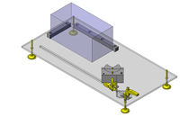
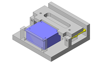
* The part in the frame is a sub-assembly unit.
-

- * Unit assembly CAD data consists of some sub-assemblies.
Each sub-assembly unit can be used as it is or can be edited.
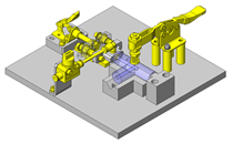
Application Overview
Purpose
- Dual axis positioning unit for printed circuit board assembly.
Points for use
- XY table unit operates with medium load and medium speed.
- Unit is used in class 100 clean room.
- The PC boards are manually loaded/unloaded.
Target workpiece
- PCB Tray
Size: W160 x D100 x H10mm
Weight: 430g
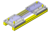
Design Specifications
Operating Conditions or Design Requirements
- X axis unit
Lower base size: W300 x L640mm
Stroke: 340mm - Y axis unit
Base size:W185 x L560mm
Stroke: 295mm - External dims. W300 x D690 x H128
Required Performance
- X axis unit
Positioning accuracy: ±0.05 / 500mm
Load: Product + Pallet + Y axis unit = 10kg - Y axis unit
Positioning accuracy: ±0.05 / 500mm
Moving section weight (Product + Pallet) = 2kg
Selection Criteria for Main Components
- Select ball screw type based on required positioning accuracy ±0.05 /500mm.
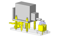
Design Evaluation
Verification of main components
- Select a motor based on applied load torque.
- Motor selection
- Load torque calculations for X axis.
- Operating conditions:
F = 0 N - External force
W = 10 kg - X axis unit weight
μ = 0.1 - Coefficient of friction (sliding surface)
g = 9.8 m/s² - Gravitational acceleration
P = 5 x 10-³ m - Ball screw lead - T = 1/(2π) x P(F + μWg)N・m
= 1/(2π) x 5 x 10⁻³(0 + 0.1 x 10 x 9.8)
= 7.7 x 10⁻³N・m - Select motor where motor rated torque > applied torque*safety factor.
- For Y axis calculated load torque is 0.19Nm .
Other Design Consideration
- PC Board fixture pallet should allow for accurate positioning of board during travel and loading/unloading.
- Ball screw stoppers are installed to prevent damage if overrun occurs.
- Since there are cables near the moving part, cable carriers should be utilized for protection.
- Provide safety measures (ball screw covers, etc.) on the moving components and install positioning sensors, etc. if needed.
- To avoid life span reduction of ball screw and linear guides, consult the accuracy guidance information for this parts.
Explore Similar Application Examples


Payment Method


On-Demand Manufacturing
Certificates


Copyright © MISUMI Corporation All Rights Reserved.